Archive
CPD/what I wish I’d known about the thesis
CPD/what I wish I’d known about the thesis
This is just a quick blog to follow on from the very useful blog by Rich Garthwaite on CPD and then talk a bit about the thesis.
ICE events.
There lots of presentations at One Great George Street which generally start at 18.30 so can be a good excuse for leaving site at a sensible time. There are a few annual talks which I have attended and thought were interesting for those in London or for those not, logging in online.
Joint Professional Meeting between the Royal Engineers and ICE, this year on 28 April 2016.
James Renie Medal – this is the top 3 successful CPR candidates from the previous year vying to demonstrate that they best reflect Renie’s principles.
ICE tour and history presentation. I did not hugely rate the presentation but having been to a few more things since, knowing a bit about the background to the creation of the ICE as well as seeing more of the institution’s home is only of benefit. The tour is by all accounts good.
Flemming Award, Smeaton lecture and John Mitchell lecture. These annual lectures which cover a geotechnics (and other topics) and two were recorded.
https://www.ice.org.uk/eventarchive/the-2015-fleming-award-competition
https://www.ice.org.uk/eventarchive/smeaton-lecture-2015
For those more geotechnically minded the Rankine lecture at Imperial College is pretty much the top end of geotechnical discussion and worth going along to hear about current themes in academia and industry. Next year (March) will be an overseas presenter. Don’t under estimate how popular it is!
These all help both towards CPD hours as well as attribute 9 in terms of participating in ICE events.
Thesis
The second point of this blog is just to point out some of the ‘what I wish I’d knowns’ regarding the thesis writing. Perhaps something others have found similar things, or not. I have got 4 points. Might be useful for Phase Twos now, albeit at preparation stage only.
Format. Slightly dull point but if anyone has resisted making use of the word styles, auto-format templates I would strongly encourage getting on board early. With 4 x TMRs, 5 x AERs and a thesis it will save hours on formatting if all of the lists of contents, figures, tables and most usefully references are all done for you. Also internal referencing within the document becomes easy as the document will self update. Highly recommended.
Timing. I found there was no time between TMRs, AERs and site work to start writing the thesis much before Christmas – clearly possible, you would just have to be more organised. Therefore the likelihood is you may choose a topic related to site and be writing it when not on site. However, it will help if you know what it is you are doing much before Christmas to allow primary data collection – as per the coursework timeline.
Primary data collection. For the reason above, if doing a site related thesis, collecting primary data from site is critical. If it’s tests on concrete or monitoring data or something else, I would advise deciding in sufficient time to get the information you need. You probably won’t manage to capture it all, so get all the details of people you might need to pull favours from afterwards.
Keeping a record. The biggest thing I am finding is not remembering quite what happened and when it happened. This is practically in terms of why some of the primary data is as it is (so I recommend keeping a site diary for sole thesis purpose of recording activities relating to the data). This is also cerebrally; trying to remember what you discussed or wrote on a notebook, 5 notebooks ago, did not work so well for me. I would have kept a better electronic record (text, photos,) of discussions, events and even thoughts to help remember everything when coming to put pen to paper a few months later.
Just my thoughts anyway.
If Carlsberg did risk mitigation for piling
Bank Street – If Carlsberg did risk mitigation for piling
I attended a site visit to Bank Street at Canary Wharf this week. Arup are the design engineers and Laing O’Rourke (Expanded Piling) are doing the piling. The activities are mainly piling so far there have been an incredible amount of problems, solutions and wonderings to be discussed. I’ve attempted to highlight some here.
The current site – note central CHS piles for reference later.
CFA piling
Test pile
The plan was to install the tension piles for the main test pile but the rig being used could not extract the auger once it had reached toe level. The issue was found to be that as the top of the auger went below ground level the material on top of it tended to pack it in on top so trying to extract resulted in the mass of soil above the top of the auger being too great to remove. Therefore a longer auger, one that extended the full pile length was needed, and an equivalently long mast. This was realised and a new rig was used with success.
As part of the specification each pile installation was checked for the rate penetration with auger rotation. The aim being to get 10 rotations per metre. This reduces any flighting where soil material is dragged into the pile and therefore reduces the pile diameter. This worked well and the rig can be automatic to achieve this.

Example of getting the flighting penetration rate too slow or too fast.
Instrumentation calibration
This is not something I really picked up on while on site Two Fifty One but is really important, especially with CFA piling as one can’t look inside the casing to check the base.
Pressure gauge – CFA piling relies upon positive pressures when filling the pile as the auger is extracted. The positive pressure implies that the concrete is being distributed all around the bore to construct the pile. The rig on this site read 0.5bar so seemingly all was well. However, something was amiss – When it came to inserting cages they only went a few metres until it was found the pile had collapsed in. The strokes on concrete pump were counted to ensure the correct volume was being distributed into a 2metre cubed box. It wasn’t so a pressure gauge test was done on the rig sensor and it was found to be faulty. The pile was being under fed by about 20%!
After the many weeks of trying to get these piles sorted for the pile test, the rig (new one) and old rig instrumentation was mended. My advice, or what I would do now I know it, would be to ask to see some of this calibration going on if I were on site while piling is going on. Arup put these tests in their specifications to ensure everything is working which seems sensible.
Cased, rotary bored piles
Secant wall
CFA rig with Secant wall behind.
Ground anchors along length of secant wall. Note which piles the anchors are in (female…?)
The secant wall was due to carry both horizontal and vertical loads. It was base grouted which is where the stiffness below the pile is improved, not ultimate bearing resistance, to reduce initial settlement. This is where the pile cures and sometime later the steel tubing inserted inside the cage is pressurised with water which cracks the bottom of the pile. [I have a photo on the way, but for now imagine a steel hose pipe running down to the bottom of the cast pile with a couple of holes in the bottom.] Grout is then pressurised inside the tube and in theory fills any voids around the base. A subsidiary check is to get a pressure to show that the grout is not just heading off somewhere. There should also be some pile uplift to prove base resistance. This was not always achieved which in theory would be a concern. But it was a secant wall so if uplift was achieved, would the piles have actually have been connected? The stratigraphy at the site is such that it is not far from ground to Thanet sands so working loads can’t all be taken in the shaft. Therefore it’s more important to understand about base resistance. One might question the point of doing a test with secant piles, other than with the confidence of reaching a certain pressure.
As a quick tangent, my colleague who worked on Cross rail, where penetration grouting was used, advised on the need to avoid over pressurising the base of piles because of the risk of heave. They only had 7m of soil above the base of the pile, let’s say 140kPa. 1 bar is 100kPa. Apparently you need 4bar to get the grout into the voids. Mmm turns out there was some heave!
Back to the site visit.
Double skin sheet pile wall
This was where the most fun occurred. 2 rows of sheet piles were installed to act as a self-supporting wall on one edge of the site.
![16838273893_3262acd6e2_o[1]](https://pewpetblog.com/wp-content/uploads/2016/02/16838273893_3262acd6e2_o1.jpg?w=595)
Near: Double sheet pile wall. This is filled with material then ties are placed and then the top section was concreted. Rear: Secant wall installed, reinforcement for capping beam can be seen.
Double wall cofferdam from the inside
The sheets were installed by pre-augering. Angela raised this as a question last year I think. Arup advised against it. As that was what the contractor wanted to do, Arup specified some come penetration tests either side of the piles to see what resistances were gained (minimum of 15 N value). A chart was presented down to the Thanet sands showing almost no resistance! The augering inside the piles had removed lots of soil and where it had influenced outside, it had reduced the soil strength to close to zero.
So what? The solution was to fill inside with concrete and grout the outside. Concrete was used to avoid having to go back and certify (if granular material was used it would probably have been difficult to achieve any compaction and may have failed further CPT tests, using concrete avoided that). This took months, was expensive and difficult to do underwater. Any plans to reuse the sheets anywhere below ground level are now out!
Summary
Firstly it was great to be back on site and see some piling elsewhere compared to Two Fifty One. The engineer had clearly been busy resolving problems but it seemed to be that most of the tests, checks and procedures were all sensible and go some way to mitigating what is really a pretty uncertain activity. One assumes all is well with the pile but really we have no idea. There is a balance between equipment, instrumentation and people. They kind of all need to chime together to reduce the risks. I feel that this visit was very useful confirmation of the sort of standards expected when piling in quite a range of issues.
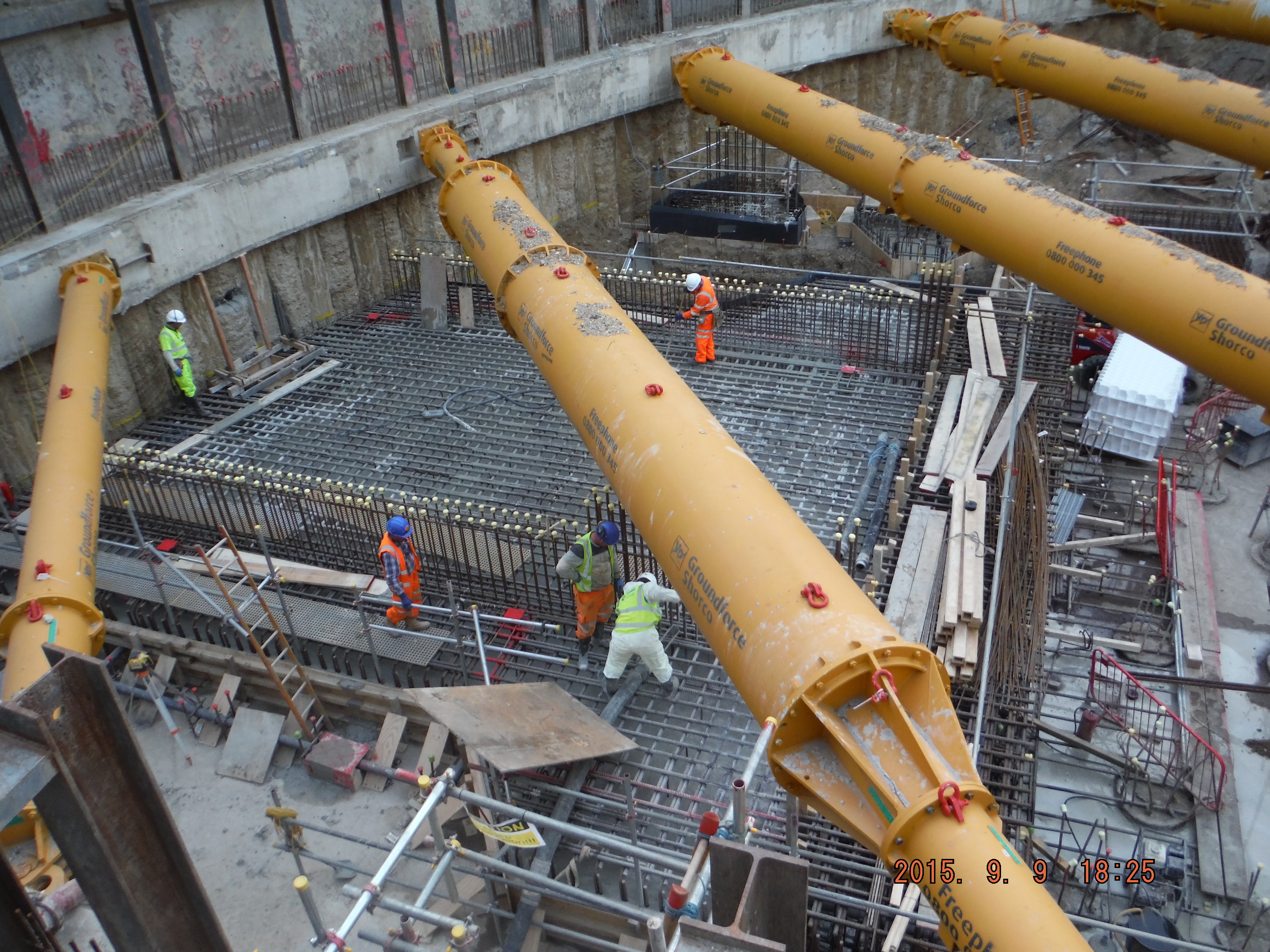
More photos


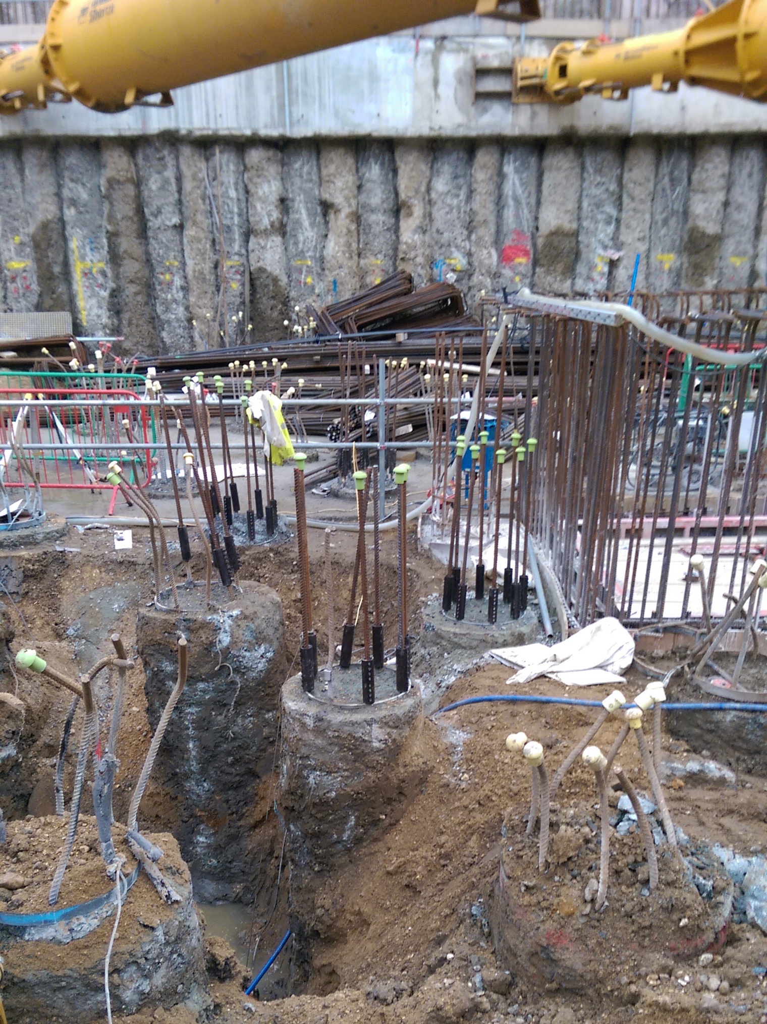
Vibrating head with circular hollow section to push reinforcement cage to pile cut off level. We used a similar method at Two Fifty One, but without the vibrating head – this methods looks far easier but needs more equipment.
![20151111_DSC_0016_resize[1]](https://pewpetblog.com/wp-content/uploads/2016/02/20151111_dsc_0016_resize1.jpg?w=322&h=429)
The site before dewatering. Left: double sided cofferdam, centre: CHS piles shown above for orientation, right secant wall.


On the way in we saw piling under bentonite. Rig with digging bucket attached removing spoil. Bentonite silos (black), green objects in front are the cleaning chambers to remove granular material residues.
Design Process
Design process
Background
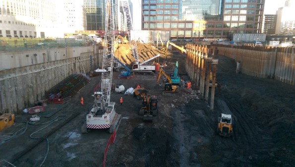
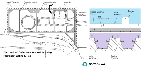
The method of getting sewerage from the current outfall point in the Thames into the new Thames Tideway sewer is via a series of chambers and a 30m shaft. At the Putney site these chambers are located on a foreshore site. To facilitate the construction a cofferdam is required.
This blog looks at the approach taken to decide how to size up some piles for design development.

Putney Embankment Foreshore – End state river wall is the rectangular box in the foreground.
Durability
Tideway (the client) require a 120 year design life for all structures. This is onerous but after Guz’s recent blog on his river travels I can see why there is pressure to prove everything meets the design life.
Tender stage
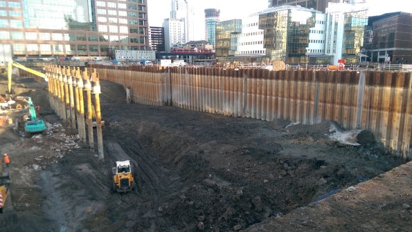
Tender documents had the permanent cofferdam as a secant wall. To enable construction an outer vast temporary sheet piled cofferdam was proposed.
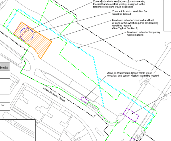
The blue dotted line is the extent of the tender document sheet pile wall. The orange box is the proposed site location.
The contractor’s tender submission was an optimised design by combining cofferdams to have a single thicker sheet piled solution which would satisfy temporary and permanent conditions.
Contractor’s tender submission – Sheet pile wall to act as a temporary and permanent wall.
The issue
Proving a sheet pile will last for 120 years is a bit tricky. The River Thames is fresh (ish) water but the fact sewerage is being discharged nearby creates a risk of microbial induced corrosion which erodes steel and makes arguing the case that all will be fine (as in only 1 or 2mm rather than 5 or 6mm difficult). Unfortunately the UK national annex is more onerous than the main eurocode, I.e. assumes more corrosion occurs.
Plan B
The contractor is keen to use a cofferdam which works in both temporary and permanent cases so have asked the Arup-Atkins joint venture to look at tubular piled options. Steel with concrete encased inside. This can be split into 2 cases. 1. Steel is non-sacrificial and last 120 years and 2. It does not.
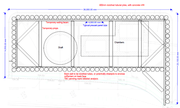
Tubular pile option – outline sketch only
How does the cofferdam get built?
- Modelling the construction sequence for either case is the same:
- Install cofferdam
- Install top prop
- Dewater
- Excavate to formation level
- Install base slab (acts as a bottom prop)
- Wait 2 years while shaft is excavated
- Move to drained conditions.
- Re-fill cofferdam/construct internal chambers to underside of prop level, back to undrained conditions.
- Remove temporary top prop.
- Finish cofferdam/structures, apply surcharge
- Excavate and place scour protection.
- Allow for some worst case tidal and tidal lag.
- Long term case – move to drained conditions.
- Case 1 – steel remains, Case 2 steel does not.
600mm tube option shown below.
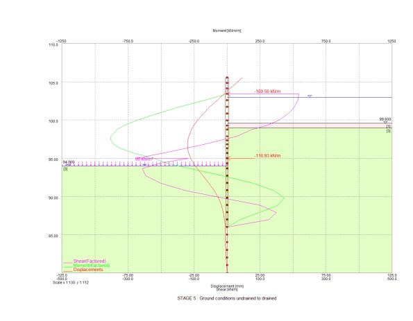
Stage 5-8 in stages above – excavation to full depth with base slab at drained conditions

Final stage with deflection of wall shown in red (105mm) and bending moment in green (1MN)
Stiffness
Understanding shear, bending and deflection throughout the sequence was key. Various pile diameters were tried but this was simply an adjustment of stiffness in the Frew model. EI based on section size, steel and concrete Young’s Modulus. 0.7EI and 0.5EI were used for temporary and permanent concrete strengths. The difference for the 120 year case comes at the final stage where only the section properties of a concrete section above bed level can be taken into account, i.e. a reduction is stiffness. More onerous is the reduction in moment capacity the section has without a steel pile included.
The results
After trying various tubular pile sizes I got to a 600mm pile for both cases above as worst moments were in temporary case (max excavation rather than maximum fill height), so loss of steel section was not an issue as final stage was still below moment capacity.
Unfortunately I made a stupid error in the fill material (somehow I assigned a granular fill a high cohesion value) within the cofferdam which meant I had lower bending moments in the long term than I should have. That was identified before presenting to the contractor so I only lost face internally.
The amended results showed that a 600mm diameter pile works in the non-sacrificial case and a 900mm diameter pile works in the sacrificial case (due to reduced moment capacity).
End state deflections were somewhat high (100mm) but all of the modelling was done at DA1 combination 2 which is not the case at SLS. Also some of the water profiling is a little unrealistic (high level inside the cofferdam, very low tide outside). There is, however, some assumed stress lockins. For example early stages see the wall bend inwards, later stages see it pushed outwards. Difficult to know if this will actually occur so this is a probable case and greater deflections might be expected.
Cladding
The front face of the river wall has stone faced cladding panels which need to be fixed to the piled wall. The connection detail raises questions on durability – casting in stainless steel brackets works but if you touch a stainless steel bracket against a mild steel pile you get greater corrosion so some thought is needed to avoid that. Additionally, final deflections up to 100mm although equate to a small angle mean the top of the cladding is off-set further in order to backfill between the cladding panels and wall. This means the cladding load acts at a greater distance causing more deflection. It also makes it harder to pour something in between the piles and the cladding panels.
Design meeting
After a week of looking at all the options the proposed solution from Arup-Atkins (us) was the 600mm pile thick enough to corrode and be acceptable in the long term. I.e. a section size that was acceptable in the long term and then a corrosion allowance added. The contractor is now going to price this option. Although more expensive than a sheet pile option, it is cheaper than doing the vast sheet pile cofferdam and there are significant savings in temporary and permanent works (fewer internal props and ties needed because of the stiffer piles).
There was sensible input from the contractor about ease of installing 600mm diameter piles versus 900mm as well as lots of points about presenting a solution which meets the client’s durability concerns.
Outcome
We wait and see what Tideway say – they may reject all options and say build it as per the tender documents. If this is the case then I wonder what the point of early contractor involvement is.
Lessons
The whole issue and reason for having to look at alternative options is because of durability concerns raised by the client. The optimised contractor solution was/is a sensible plan and on a pain/gain contract it is worth trying to make savings.
The best thing I see having gone once around the process is developing multiple options to give the contractor the choice of what to present to the client. This enables a solution to be put forward on technical merit.
The plan to get the tubular pile costed before presenting to the client presents risk (for the contractor) has failed because of how busy the commercial team is right now which might turn out to be an issue.
I have learnt a lot about the importance of how something is to be done without the need to go into detailed calculations – certainly the case at concept design stage.
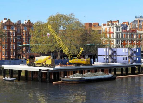
Temporary works jetty solution to build the new site. All by river approach demonstrated with barge removing spoil.
Shear and UPL
Shear and UPL
This is not what I am doing but a technical problem has popped up on a site one of the members of my team oversees and I thought it was interesting.
Imagine a secant wall in a rectangular formation with an in situ basement box to be poured inside it – see below.
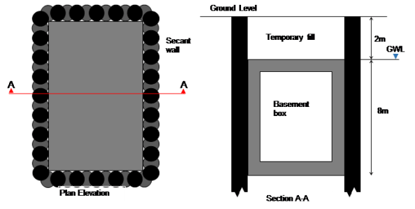
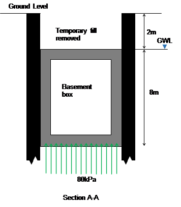
The base of the box is at 10m below ground level and the water level is at 2m below ground level. Over time as water pressures return this creates an uplift stress of 80kpa. Assuming the base and walls have a downward stress of about 60kPa this leaves a remaining 20kPa downwards stress needed. When the fill is placed above the box this results in a net downwards pressure (bulk weight of soil (20kPa multiplied by 2m gives sufficient resistance). However, let us assume that the fill gets removed for a subsequent development (as is planned).
The risk is uplift failure (UPL), I.e. the box tries to move to the surface because of the buoyancy effects.
The solution.
Dowel bars (yellow) between the male secant piles and the internal box provide shear resistance (green arrows) to stop the box lifting up.
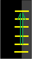
Dowel bars fixed between piles (black) and inner box (grey)
The problem
Suppose over time water is able to get between the secant wall and new basement box. Over a bit more time the gap between the secant wall and box might increase a bit more. So the dowel bars now act in tension between the secant wall and hydrostatic head (blue) pushing the box inwards. Over more time still and the dowel bars act in tension due to the lateral force (horizontal green arrows) applied by the hydrostatic head which makes them strain, or elongate, and therefore have a slightly reduced shear capacity.
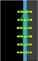
Tension in dowel bars created by hydrostatic head, dowel bars strain (extend).
An 8m depth of water implies 80kPa or 80kN if the dowel bar resists one metre square (for simplicity). E=(F/A)/(ext/original length). Ext/orig=(80/pi d2/4)/E, E (210GPa), d =40mm, implies 0.2mm/600mm multiplied by E (210GPa) equals 70MPa axial stress.
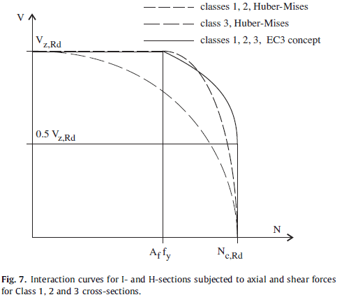
Remembering back to EC3 days or Von Mises, as axial force increases, shear decreases. Therefore this increase in stress in axial force (N) may reduce shear (V) to below the design capacity – Vz Rd reduces as axial force increases.
The question is why does the reinforcement bar extend by 0.2mm? The design specified a plain bar, the contractor installed a normal ribbed reinforcement bar into the secant wall which would generate tension between the secant wall and inner box as the hydrostatic head builds. A smooth bar would also lateral movement without reduction in shear capacity.
The problem is worsened when uplift occurs because the rebar it put into bending and therefore undergoes further reduction in capacity. See the 3D graph below where moment reduces capacity even more.

The solution (2)
Install a sleeve over the rebar thus removing the interlock effect of the ribs on the inner wall. This allows lateral movement of the dowel bars to avoid any axial force. Uplift is ten resisted by the dowel bars as planned in the design!
Summary
Clearly there are a number of assumptions and simplifications in this blog (basement box would also resist some lateral force reducing movement, soil type ignored, move to drained approach). I thought this issue was seemingly minor, but with an accumulation of risks (tri-axial forces) the consequences could be high. I would argue the likelihood of the risk arising is low but having specified a design solution to a complex problem, Arup was not going to reverse its view (with full finite element analysis to back up assertions) just to hurry the job along.
Thames Tideway Epic induction
Thames Tideway Epic induction
I attended the Thames Tideway Induction this week. Even if Carlsberg did health and safety inductions it would not be half as good as this was. It was simply Epic, which actually stands for Employee Project Induction Centre.
The Problem
The Tideway Project approach to Health and Safety is an attempt to re-set precedence where currently major projects (such as Olympics, Cross Rail, Heathrow) tend to have an increase in RIDDOR incidents at the start of a project (as new employees get bedded in) with a peak a few months in, then a decline to a plateau and a rising spike at the end (towards handover). I think this is pretty similar to operational accidents in theatre where there was a learning period which caused injuries, then lessons are learned but by the end there is some complacency resulting in a final spike.

Graph of RIDDOR incidents – representative only and recreated from induction slide – hence magnitude of numbers removed.
Using the accident numbers from previous projects against the number of hours planned to be worked on the Tideway project would mean:
- 2 deaths
- 1500 life changing injuries
- 10,000 lost working hours
Clearly you can’t accept that (or effectively plan to kill 2 people and injury 100s more) and so the whole push from even before starting is to set the standard at high in hope that will result in a better outcome.
The induction
Tideway have rented office space next to MI6 and have created a mock up accident scenario. I’ll be light on the details in case anyone else goes through it but effectively the day starts with you in the site canteen and 2 workers arrive (taking us, the audience, by surprise). They chat about random day to day stuff. They then leave to work on site (audience follows to site). There is then an accident of one of the workers who later dies (scenario, not real). The audience then moves to another room – HSE investigation which is pretty tough for the audience too, then the flat where the employee lived (heavy play on consequences of such an event), then a room split between a site office and a head office to hear background conversations leading up to the event. Back to the canteen (to recover) and start the practical training.
The day is run by a team of actors from the Active Training Team company who role play through the scenario but then are there to re-run the scenario to talk through what the causes were and what actions might have resulted in a different outcome. This is similar to the role play equality and diversity training the Army now do but far more interactive.
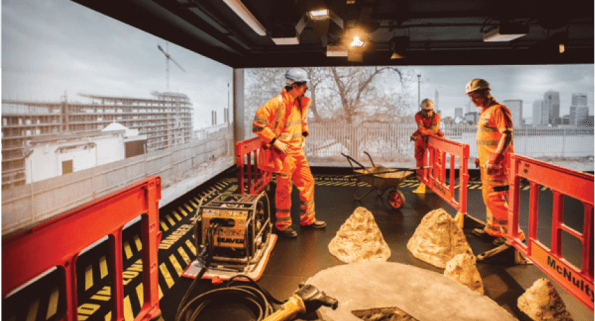
Scene from the induction centre – actors playing very convincing construction workers
The afternoon was filled with behaviour based learning – all practical group discussions which included at some stages going toe to toe with the actors on various other scenarios. The point being to learn techniques and methods for all levels of construction workers to improve their behaviour and mind-set towards health and safety.
Level of Engagement
There was one 15 minute presentation which was delivered by the CEO of Tideway (Andy Mitchell – recently on the front of NCE magazine for different reasons) of a £4bn project so it is clear where his focus is.
Methods
The health and safety approach is pretty impressive, especially if this is to be the standard that every employee (over 5000 expected) over 5 years goes through it. They have got a comprehensive approach covering worker language skills, issuing of the best PPE, lessons learned from Heathrow, Cross rail and the Olympics, 3-monthly stand downs across all sites to discuss H&S issues, and a drive to have the most secure sites with the best welfare facilities.
Will it work?
I think the recognition of the problem and desire and motivation to change history is fantastic. However the difficultly will be in getting everybody to embrace it when budgets are squeezed, timelines are reduced and concrete wagons are ready waiting on site. If the collection of parties play their roles well – designers design safe and buildable structures, contractors allow for safe working methods, invest in employee training and Tideway live up to the standards they are talking about then I see no reason why the injury levels cannot be reduced. I do not believe there is an argument for the irreducible minimum in this instance with money and time, quality (in health and safety) can be achieved.
Summary
It will be interesting to see how it plays out. There are some particularly hazardous working environments: underground, confined spaces, deep excavations and over water. The 3 sets of joint ventures (8 different contractors) will have a far more onerous task of getting people to acknowledge the risks and how to mitigate them. A balance between having to produce paperwork against the level of risk an activity possesses will have to be considered to make sure effort is best placed to achieve the desired effect. Finally, with this significant investment and change (improvement?) in mind-set to health and safety what happens if it does not work – are all major infrastructure projects doomed to kill and maim people. It is clear there is buy-in at the top and this is being pushed from the highest level so hopefully it will succeed.
Thames Tideway Tunnel – The start
Thames Tideway Tunnel – The start
I have now started on Phase 3 with Arup and am working within the geotechnical team on the Thames Tideway Tunnel project. To avoid this blog getting too long I’ll present some of the background, my part in the plan and a brief discussion on sustainability.
Background. The London sewer network is predominantly a combined foul and surface water system. The sewers convey the waste to treatment works for processing. However, when it rains heavily the capacity of the sewers is often overwhelmed and the excess sewage is deposited into the Thames through combined sewer outfalls. To reduce the frequency of incidents of raw sewage discharge into the Thames each year the Thames Tideway Tunnel project aims to capture combined storm and foul water within a new 7.2m diameter tunnel running from Acton in the west to Abbey Mills in the east.
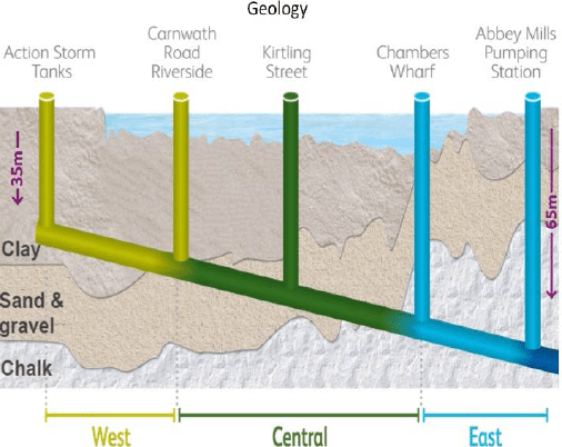 Overview of tunnel alignment through the London geology.
My part in the plan. Effectively the project is divided into three sections: west, central and east. Each section has a number of connections to capture the existing combined sewer outfalls and convey the flow into the new sewer. The process is generally to have an interceptor chamber which feeds into a further set of chambers to attenuate flow and then a drop shaft to connect to the new sewer. I have 2 sites to design the foundations for: Putney and Barn Elms. Arup are not responsible for the main sewer tunnel or drop shafts but are responsible for designing the other elements, including the chamber and connecting culvert foundations.
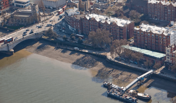 View of Putney Foreshore Embankment site
Putney has some interesting challenges: The connection to the existing sewer outfall is directly below Putney bridge. One of the proposals sees there needing to be a number of bored piles in the foundation design (questionable reasons: either as tension piles to avoid buoyancy issues or to minimise long term settlement between existing bridge outfall and new structure). Getting a piling rig into position will be a challenge due to headroom constraints. One method sees a temporary sheet pile wall planned to be installed around the whole site area (under the centre of one of Putney bridge arches (max headroom)), then dewatered, excavated and re-filled. The temporary works are out of my scope but understanding how the contractor will carry out the works is clearly important.
 Existing outfalls (left), proposed interception chamber on right – this is 7m deep with a number of bored piles within the foundations proposed!
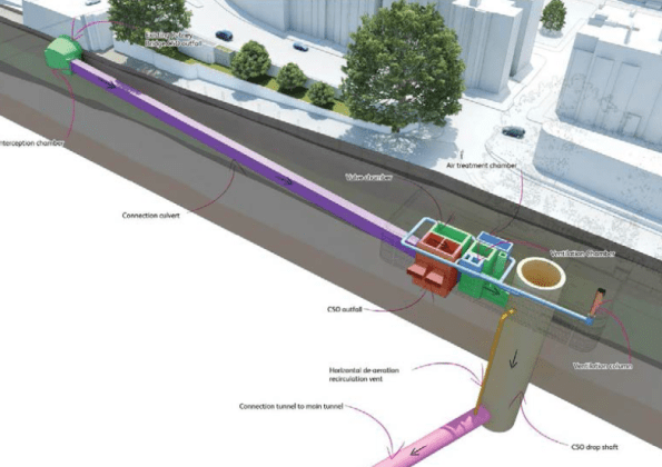
My responsibility is designing the interception chamber (left green), connecting tunnel (centre purple) and attenuation chambers (right brown/green/blue) foundations. Drop shaft and connecting tunnel to main sewer (out of picture) is not my responsibility.
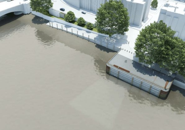 Illustrative view of completed site.
So in terms of what I am doing – initial work is scoping further ground investigation for where there is risk – lack of confidence in certain parameters for example. Next comes a geotechnical design report and then will come developed design, detailed design and finally construction issue information. This aligns pretty well with the RIBA stages of work too.
Sustainability.
The aim of the project is to provide overflow capacity to the existing sewer infrastructure in order to reduce the frequency of sewage discharges into the river Thames.
Advantages and Disadvantages. This project will bring political and social benefits of a cleaner river and evidence of better waste management practices within the UK. The economic benefit is more questionable. Construction costs have multiplied by a factor of 3 from 2005 to £4bn raising the question of its cost worthiness. Moreover, other options of attempting to use land as attenuation (green field sites as soakaways, green roofs) through green infrastructure have been argued to be sufficient to meet the demands of future predicted storm levels. The legislation is in place to enforce greener infrastructure but it appears planning authorities do not follow this through as judicially as they might with greater resources.
The accuracy of the sewage over flow statistics has been questioned, with some groups stating that the level of pollution entering the Thames is lower than the Environmental Agency’s limits now and so the construction of the new sewer is a complete waste of money.
As part of the project, the Beckton Sewerage Treatment Works will also be upgraded to cope with additional demand. The disadvantage of increasing the amount of surface and foul water captured will be the need to pump all of the water through 60m of head at Abbey Mills which will result in higher maintenance costs and require significant energy to achieve. If some of the storm water had been captured through green infrastructure assets there would be less energy required to process it at the other end. Reducing the amount of storm water ever reaching the sewer therefore brings a double saving.
Clearly reducing the sewage discharge into the Thames is beneficial and the project will significantly improve the condition of the river. I suspect as a country likely to be at the forefront of developing environmentally friendly solutions the green infrastructure piece will come but for now at least a solution has been produced to an acceptable cost, timeframe and quality, assuming all goes to plan!
In summary. This project will be my sole focus. I have started to investigate wider strands within it – financial/commercial for a better background understanding but with a company like Arup, unless specifically requested, phase 3 will tend to be focussed on one major project.
Site Two Fifty One – A few examples of how things can be done.
Site Two Fifty One – A few examples of how things can be done.
This is just a quick blog with an update of where things are on site. If there is an area of interest I will expand/find out answers in the comments.
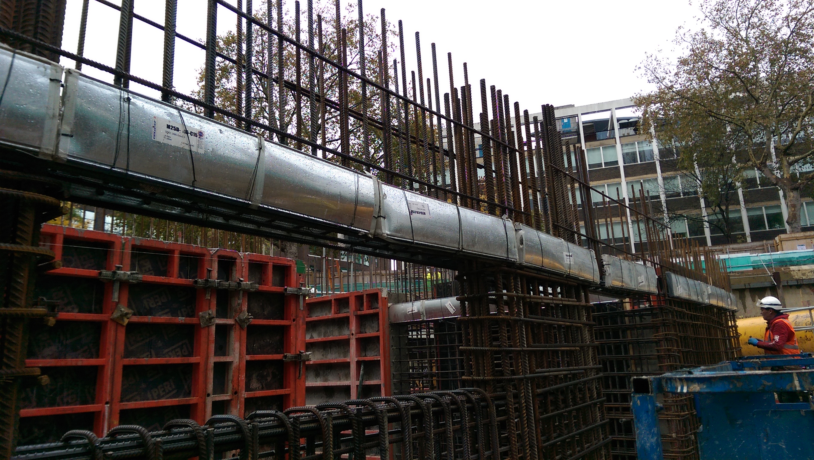
1. Kwika strip slab starters. As previously mentioned we would be using kwika strip in the walls. This shows how they look pre-pour. The bars have about 30 mm cover within the case.
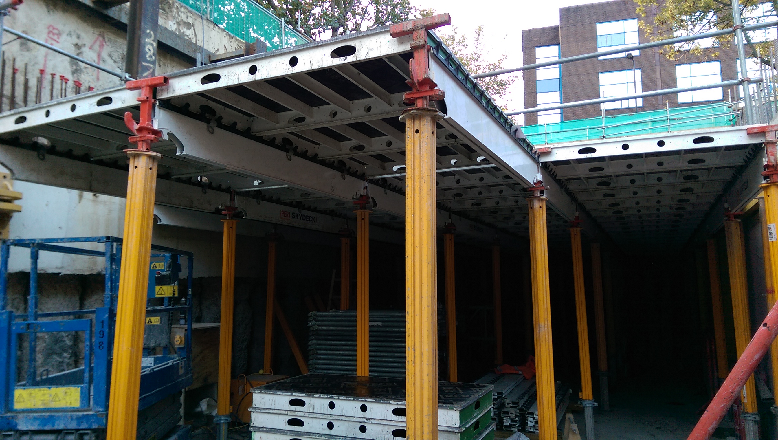
2. Sky deck falsework. This is a Peri system which is quick to erect. It requires bracing using chains and a section of trusses to transfer 2.5% of the vertical load. We did not silicone between joints but used a plastic t-section. There was some grout loss down the faces of the walls and columns which was washed off to avoid disfigurement.
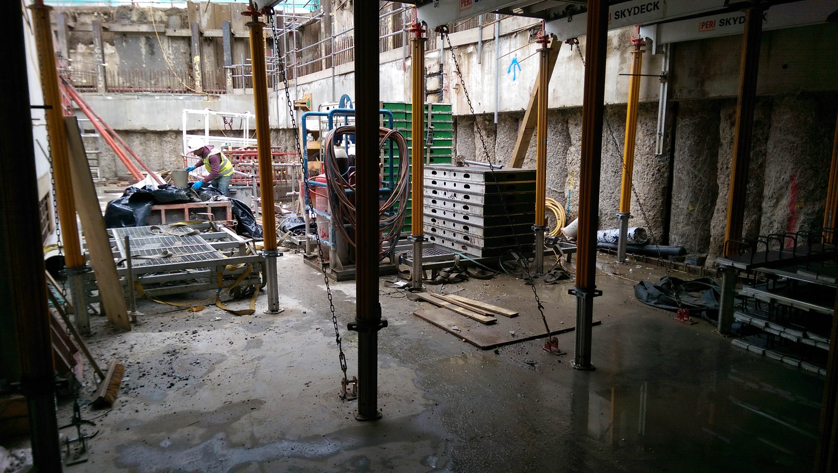
Chains providing lateral restraint of the Skydeck.
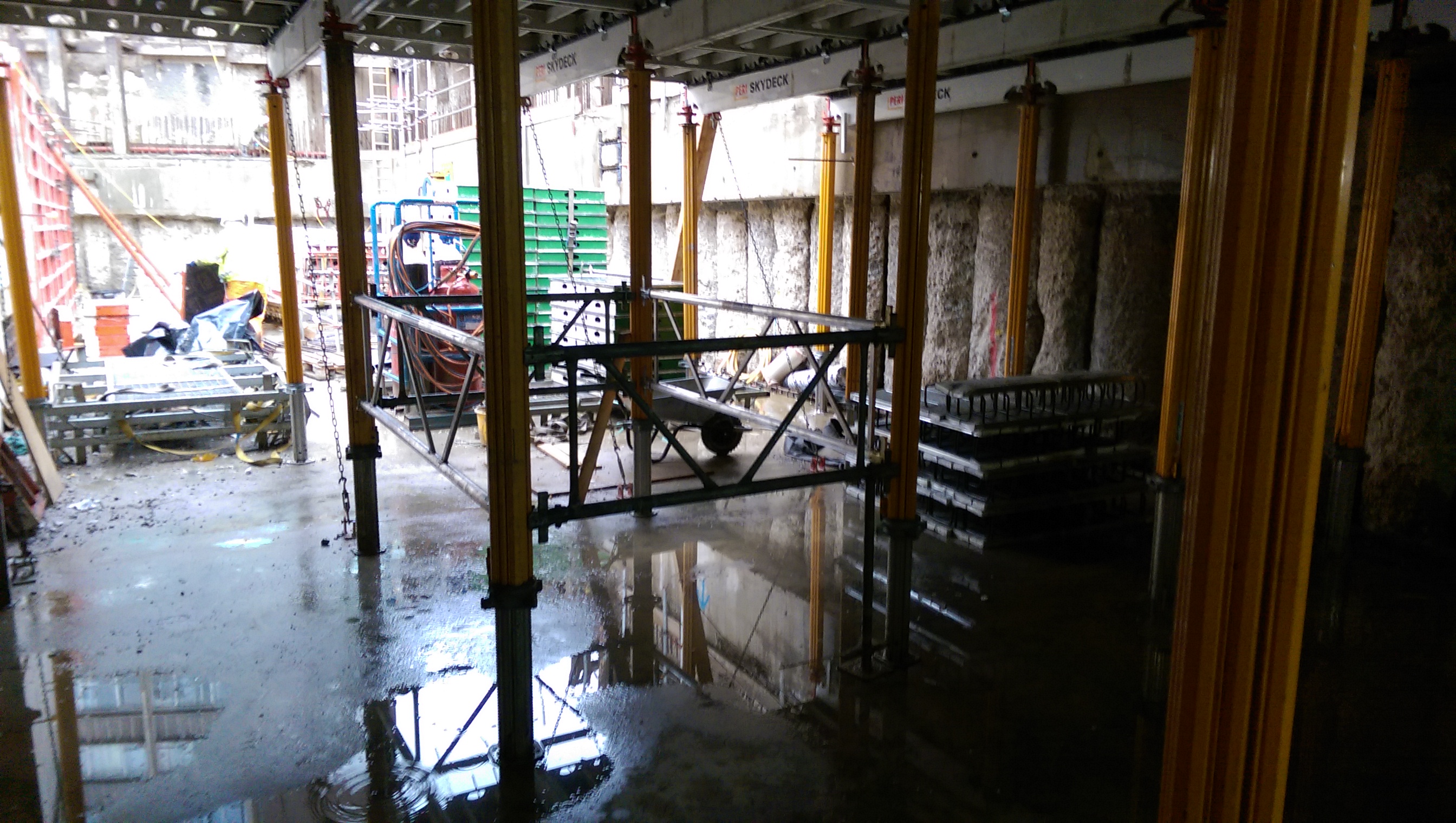
Braced panel to transfer vertical load to the ground.
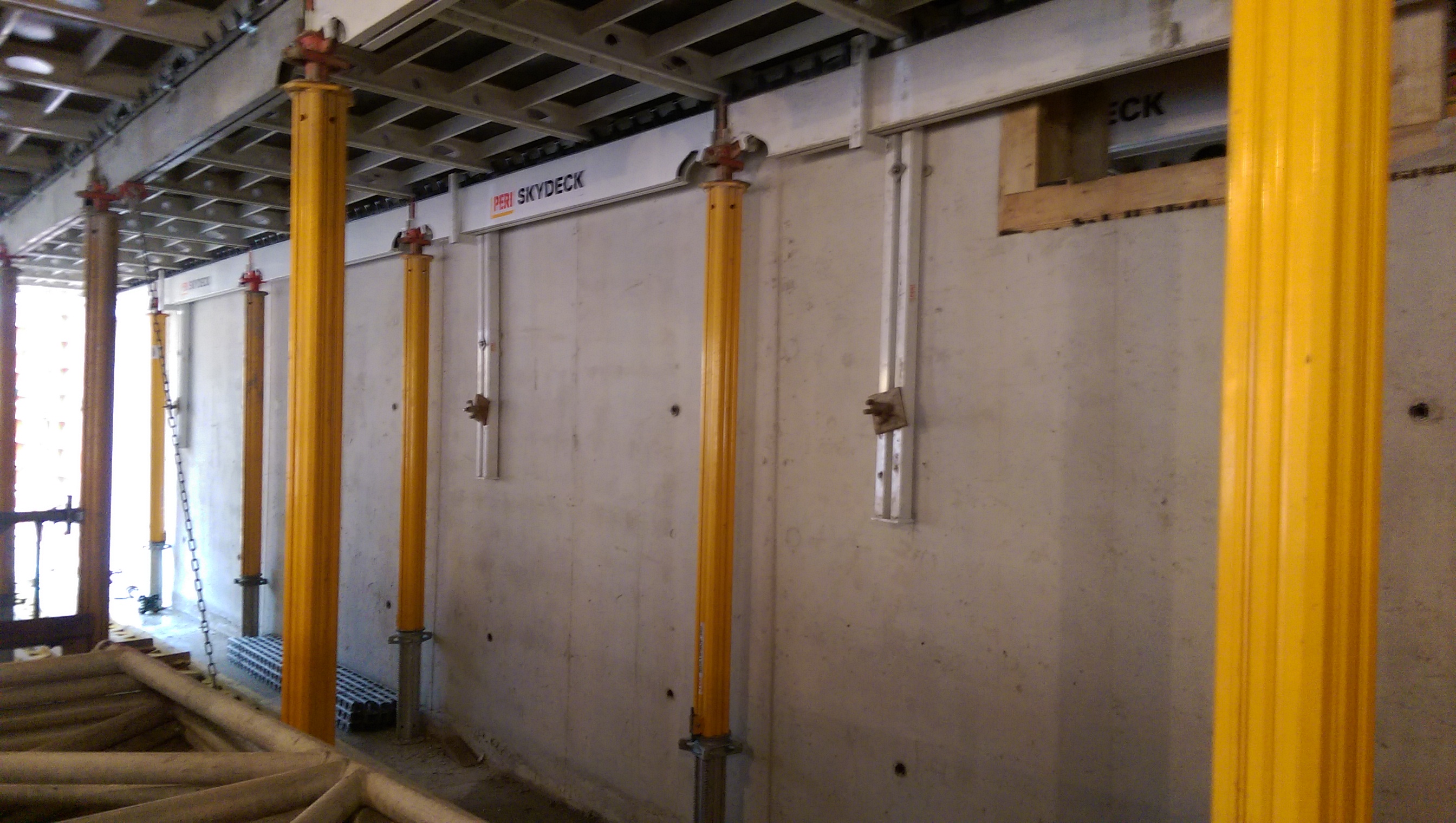
Wall brackets to provide lateral restraint.
3. When can I strike? The next challenge was to know when the falsework could be struck. The method used is based on a crack width assumption that compares construction loads with unfactored service loads against the concrete strength (fcu) (see page 186 in ‘CS30 Formwork. A guide to good practice, third edition, 2012’ for full details). This slab is for a plant area so the ratio is low resulting in the concrete strength required to be 15N/mm2 to strike which should be achieved in 4-days. However, we will crush cubes daily and have thermocouples placed in the pour and cubes, so we will correlate to give an accurate actual concrete strength, which if reached earlier than 4-days will mean we strike the falsework sooner.
Skydeck falsework being installed at B1 level.
Slab pour – puddling complete around columns.
4. Concrete miss-match. Some of the building’s columns are 60N/mm2 whereas the B1 slab is only 40N/mm2. Therefore within the B1 slab pour a section of 50N/mm2 concrete was puddled around the column locations to avoid a miss-match in strength of more than 10N/mm2…
Hi-rib stopend at near-side of slab pour, near column starter bars.
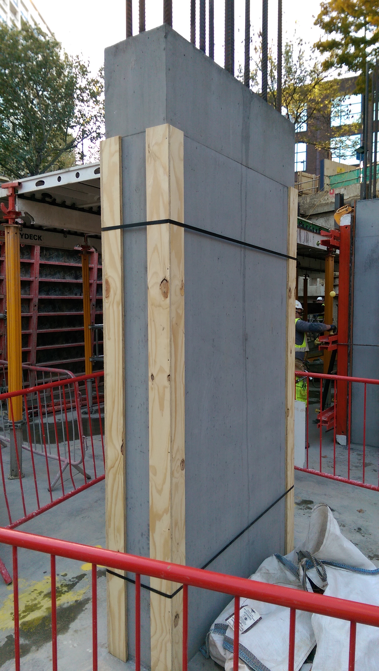
5. Column formwork. 2-sided formwork – props used to keep column vertical rather than taking significant horizontal load. The horizontal load is carried within the internal ties.

6. How do you build this? This is a sump 3.1m deep by 600mm . 600mm. To install any sort of formwork and then strike it would be too small a pit to put an operative in to work. Not necessarily the best solution but a quick one is to use precast sections (similar to manhole rings) to build up and pour the walls around it. The outer size of the chamber had to be increased but there was no spatial constraint to prevent this so hopefully the plan will work!

Two Fifty One – Concrete continuity
Two Fifty One – Concrete continuity
RC Detailing.
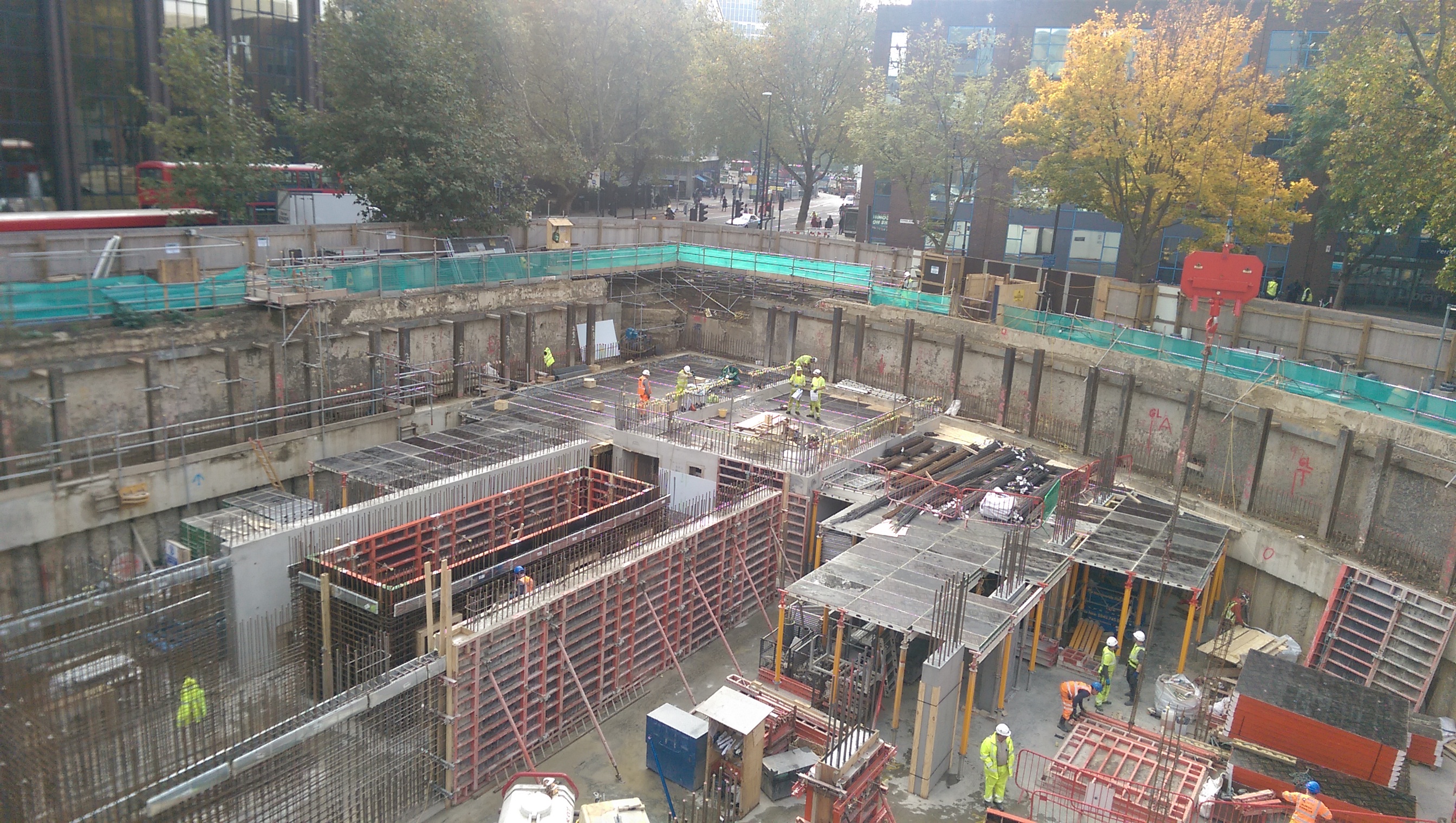
By way of background, Two Fifty One has two levels of in-situ basement followed by 40 storeys of precast concrete to form the tower superstructure. The lateral stability is provided by shear walls which form a perimeter around the lift and stair shafts.
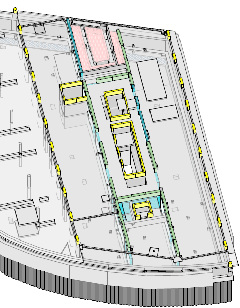
Substructure – The green walls represent the shear walls in the tower. Inner yellow walls demote lift pit and stairwell.
The slab to shear wall connections in the tower basement floors have been designed using kwikastrip. These are pre-bent bars that sit within a case and then are bent on site at a later date.

Kwikastrip pull-out bars
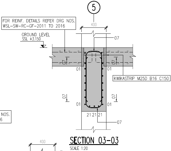
Kwikastrip used to form wall to slab connection joint.
The more typical method would be to run slab steel through the walls as shown in the figure from the IStructE Standard Method of Detailing Structural Concrete.

The reason is to enable the walls to be poured in higher strength concrete than the slabs. This is because the walls carry the loads down the building to the raft foundation to the piles below. From a buildability perspective it means the walls need to be cast to the structural slab level (ssl) rather than to the slab soffit. Other than the fact the falsework had initially been designed to soffit level this not a problem.
One of the key considerations of using pull out/continuity reinforcement bars is the rebending of the reinforcement.
Bending reinforcement on site presents the risk of overstressing the steel by bending it to too tight a radius thereby weakening it.
The bar diameter of kwikastrip is limited to 16mm and a bar bending tool should be used to rebend the reinforcement. The IStructE Standard Method of Detailing Structural Concrete states that “where it can be shown that the bars are sufficiently ductile (kwikastrip uses Class B steel so is acceptable) bars not exceeding 12mm size may be rebent provided care is taken not to reduce the mandrel size (radius of bend) below four times the bar size”. The same is also be true for 16mm steel at seven times the bar diameter.
This requirement needs close quality control to ensure bars are rebent correctly. The walls use both 12mm and 16mm steel kwikastrip making it even more important not to confuse the bar diameter with bar bending tool (or the strips themselves). Halfen (kwikastrip supplier) state: “the straightening tool is a steel tube with a specially shaped end and an internal diameter only slightly greater than the diameter of the bar to be straightened” hence strict quality control is needed to firstly use the tool (rather than any old scaffold tube) and secondly use the correct tool.
Other considerations include:
Increased time to fix the items in (fiddly).
Procurement ordering time – the items need to be ordered specifically, not called off from reinforcement schedules which requires lead time and storage.
Increased cost (circa 8k for one level of slab) compared to extending the reinforcement bars a short distance. Cost of standard stock steel per tonne is less than equivalent of weight of kwikastrip.
The structural requirement to maintain concrete continuity has overridden the practical installation disadvantages and that is how it will be built.
Other points
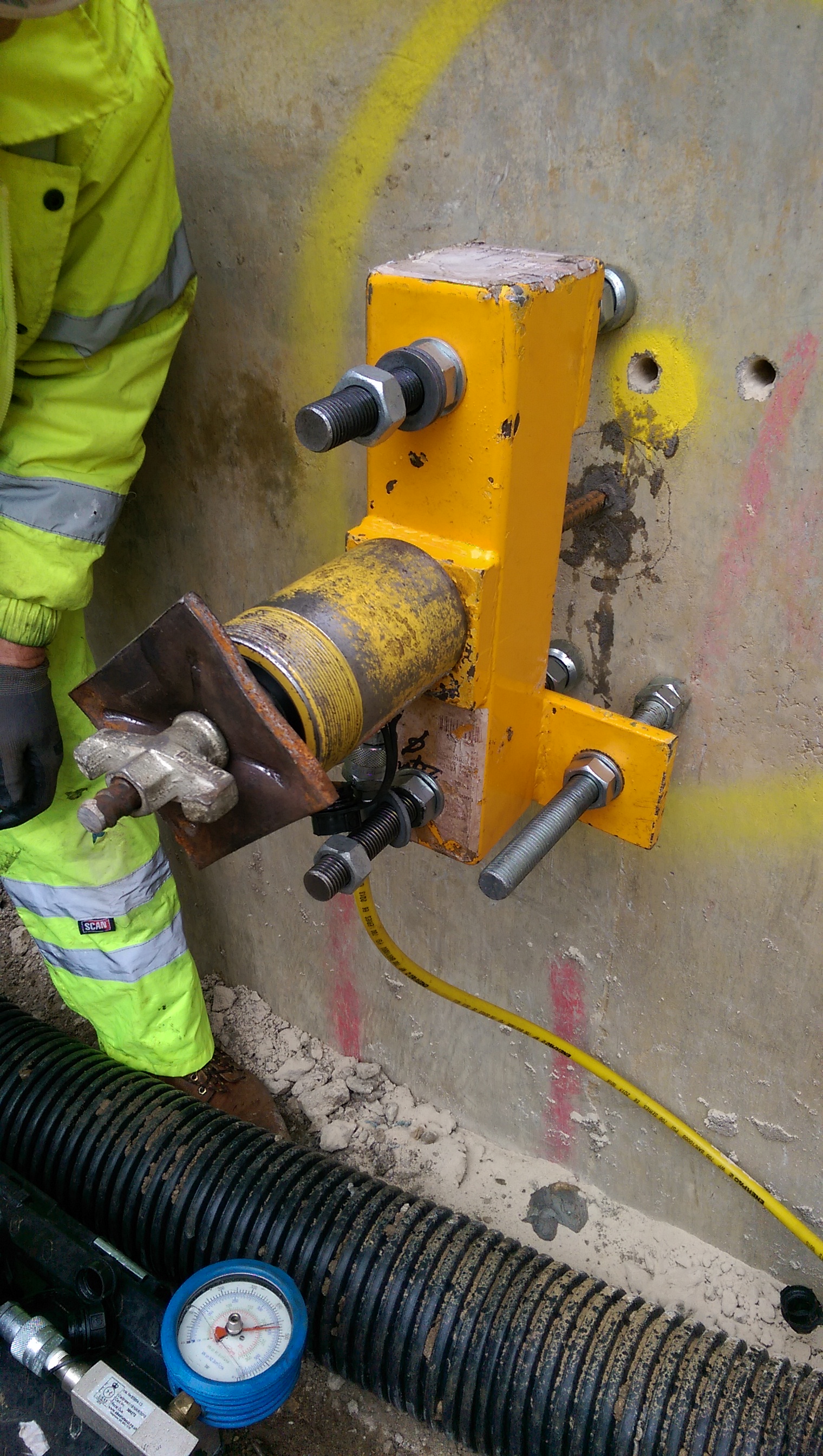
Pull out tests. We want to use an existing retaining wall to resin in dywidag bars to connect a one sided shutter to form a new retaining wall. We will be using Peri shutters with pre-set tie bar positions. The pull out tests showed no movement at 150kN, other than a bit of feet penetration into some old plaster on the wall. At 150kN there was a crack sound as the resin slightly debonded from the concrete and at 200kN there was evidence of some a cone failure (see circular crack around bar). The aim was to confirm a 90kN force would not be exceeded which the tests proved was the case. Interestingly the critical factor in pouring the walls will now be the pressure on the formwork soldiers and walers, rather than tie force. Therefore the rate of rise will be controlled especially because we have retarders which increase the pressure exerted on the formwork.
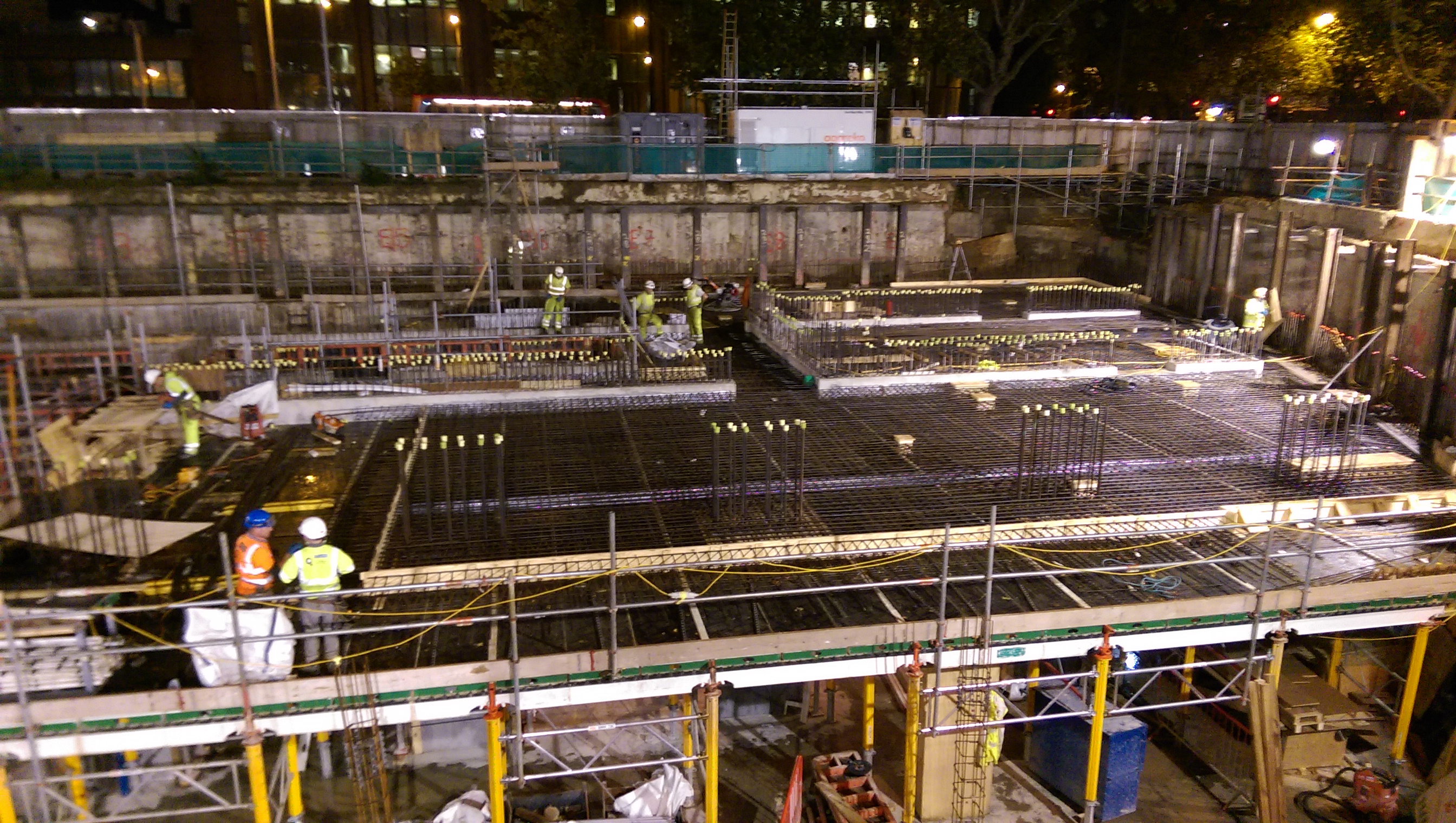
Propping scheme. The view below shows the site with the props spanning over the basement. In order to remove the props the basement level 2 slab must be cast halfway between them. This was creating a bit of a pour sequence issue as clearly the props are not angled in a way which suits the foundation layout!
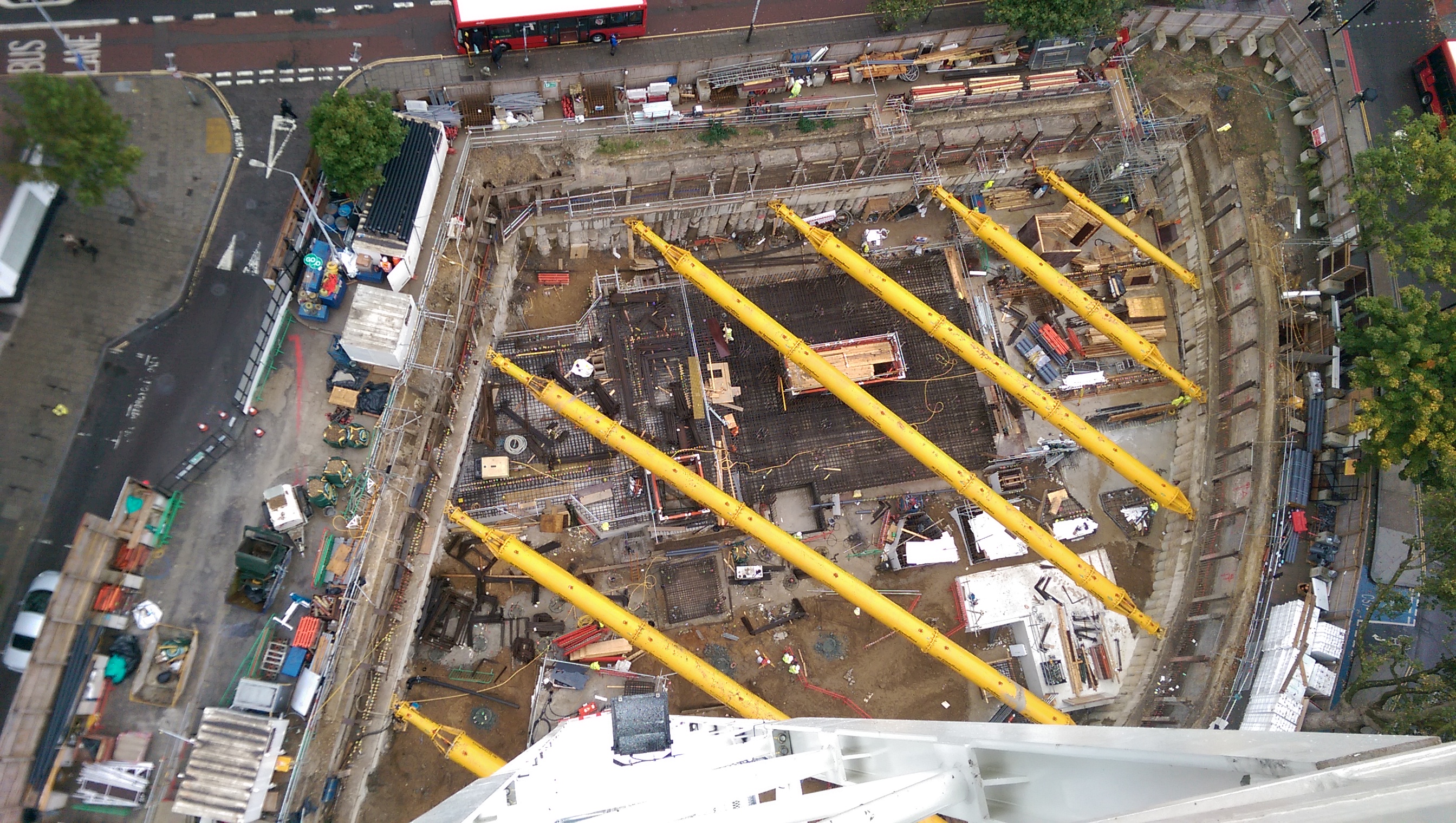
Two Fifty One from our first of 4 tower cranes.
Site Two Fifty One – Drainage testing and Assessment of plunging reinforcement in piles
Site Two Fifty One – Drainage testing and Assessment of plunging reinforcement in piles
Drainage testing
As I mentioned before the underslab drainage needed testing before the concrete slab was cast. The method for this was actually very simple. There are 2 common options: air and water tests. We have done air tests. The method is to bung the openings in a run (such as gullies, rodding eye, down pipes, etc) pressurise one end with a pump to 100mm on a U tube Manometer. Over a 5 minute period the drop should be no more than 25mm. If this is the case move on to the next run, if not, test shorter sections until the leakage point is found.
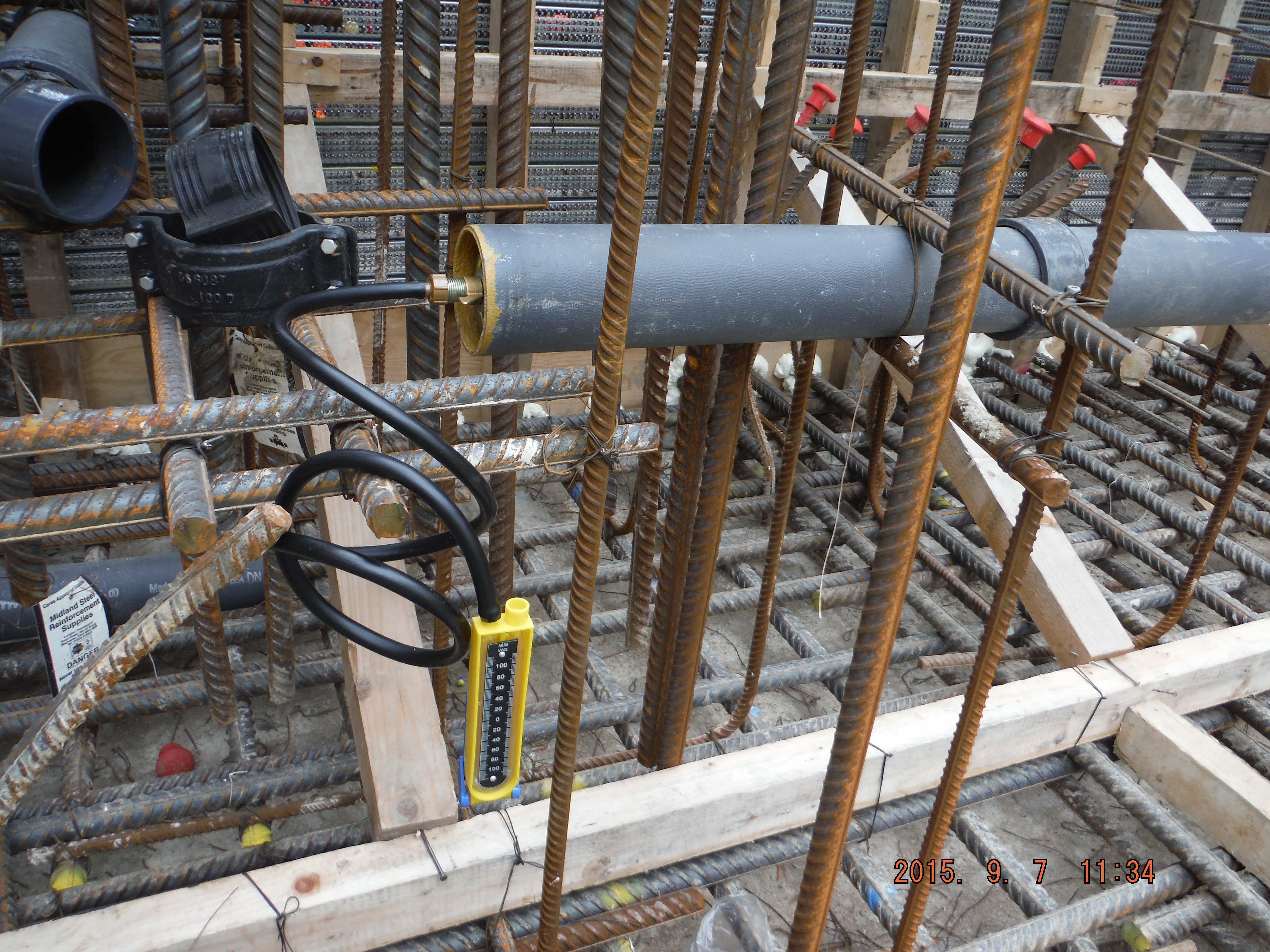
Manometer used to confirm pipes do not leak.
Tension
How to get tension anchorage. We have installed our first tower crane base this week. The 80m3 pour is impressive, not least because of the 0mm tolerance on the crane base but more because of the W bars used to provide tension reinforcement within the pile cap.
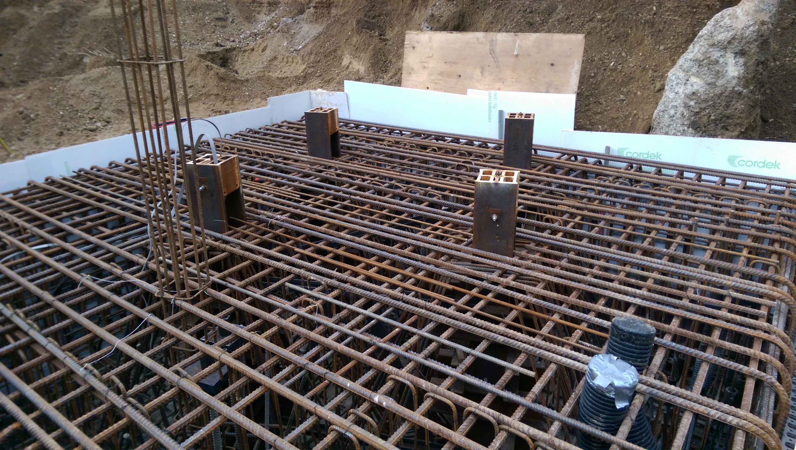
If you open this image up and look at the 4 tower crane legs you can see the “W” reinforcement.
The other interesting point is that dywidag bars the length of the piles (about 26m) have been installed to avoid the whole pile cap rotating. However the anchorage length required is greater than the height of the pile cap. To solve this, large (676cm2) plates and nuts have been used to give greater anchorage. Has anyone else seen this method used?
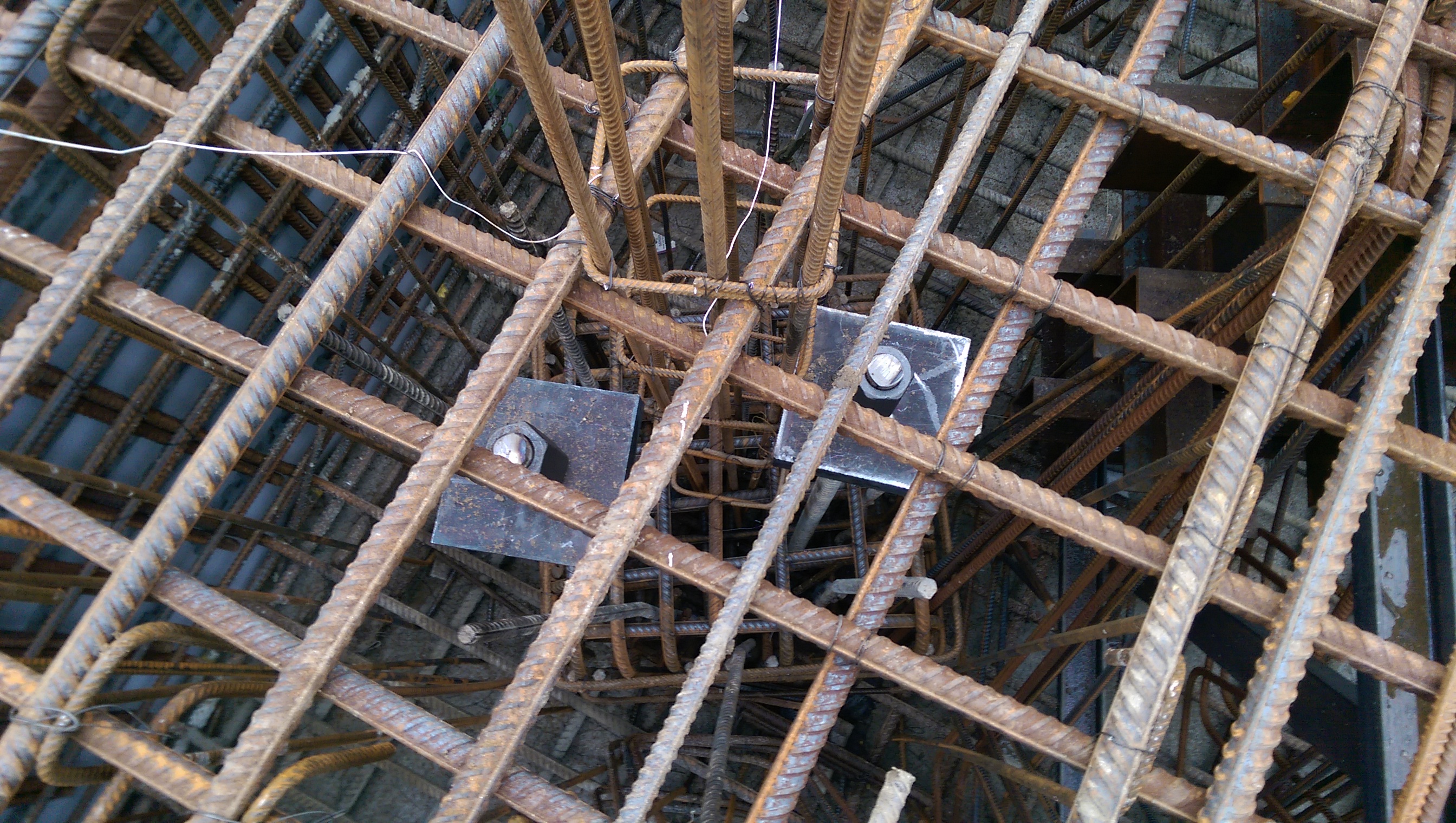
Square plates used to provide additional anchorage.
Piling methods
The piling method at Two Fifty One was to install piles at ground level, plunge the pile reinforcement and then excavate ground to formation level (approximately 5m lower), breaking the piles are we go.
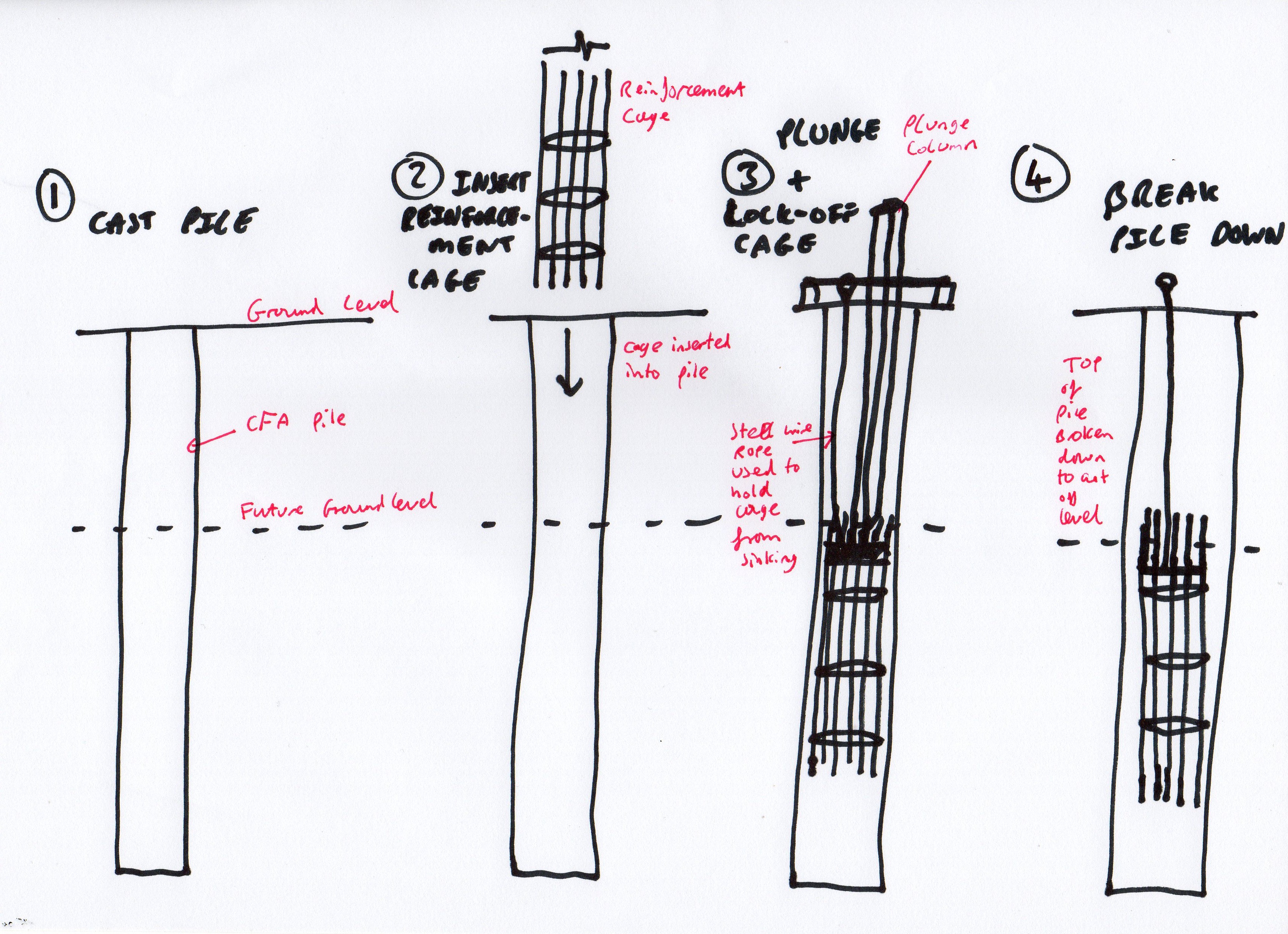
2-Year old’s impression of plunging pile reinforcement cages
This has a significant disadvantage. Let’s assume 300 piles, 5m waste, 0.75m diameter, £140 per m3 of concrete equals a little under £100k in waste concrete, plus time to break piles, plus muck away time.
However the advantage is that the piles can actually be installed. If the site was deeper the props would be in the way of the piling rig and getting the rig out of the site would have been pretty tricky. Bearing in mind the piling package was about £4M, this represents a 2.5% fraction of the cost.
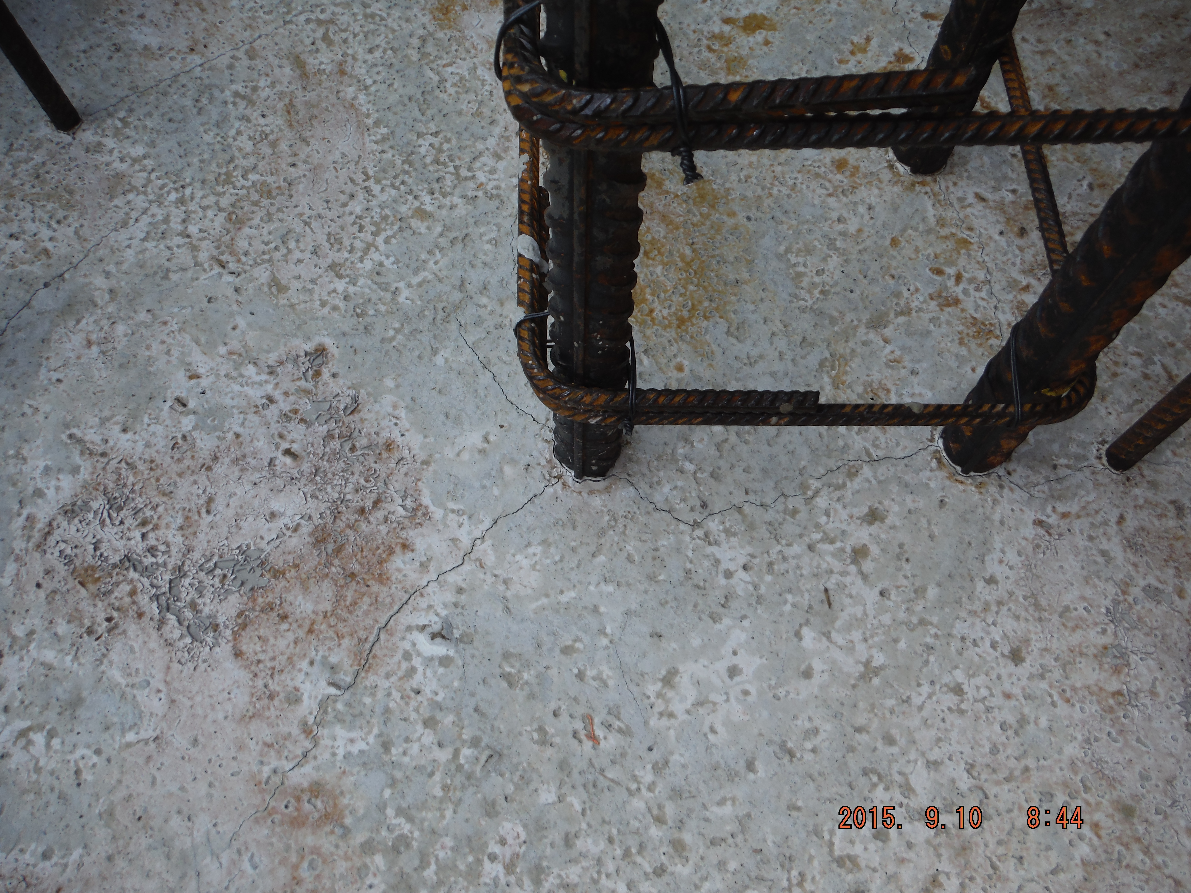
Further issues. Submerging pile reinforcement cages to an exact cut-off level means it was not done very well. Mostly are within tolerance for anchorage requirements but some are too low.
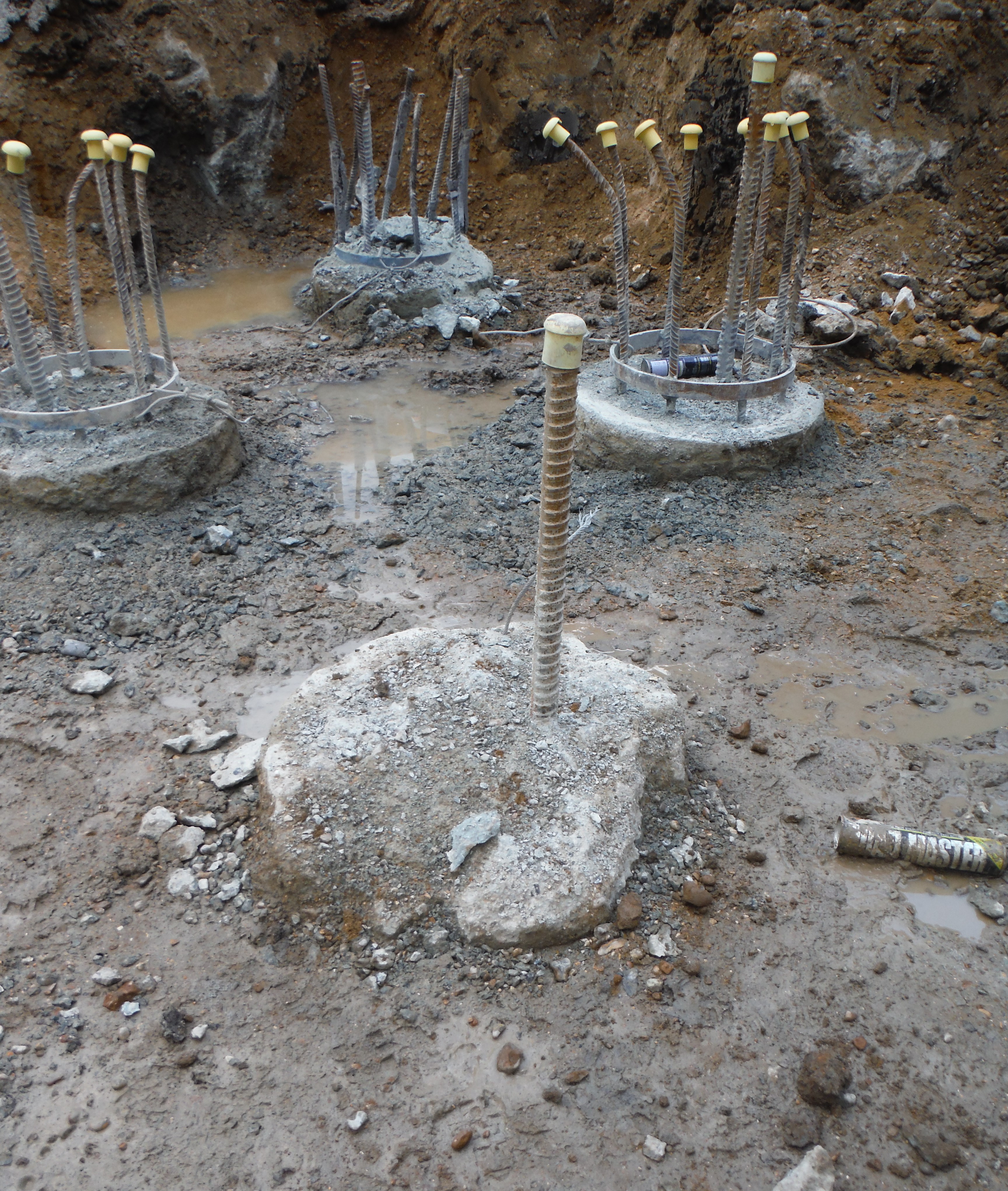
Spot the difference – something is not right about this pile…
Moreover, in order to dig deeper pits we have had to cut some reinforcement down (to facilitate excavator arm length reaching to dig level). Therefore to extend the reinforcement back to the correct length couplers have been used. Bar diameter dictates coupler size. The common MPT couplers seem to be what everyone has heard of, they are British Board of Agreement approved, but unfortunately not Certification Authority for Reinforcing Steels (CARES) approved. Laing O’Rourke only allow CARES suppliers – due to adhering to certain quality standards and also as a wider corporate image piece. Therefore once this hurdle was overcome, the couplers were installed. As a final point the locking bolts should shear off to demonstrate correct installation.
Couplers used to extend pile reinforcement.
Two Fifty One – Curing Methods
Two Fifty One – Curing Methods
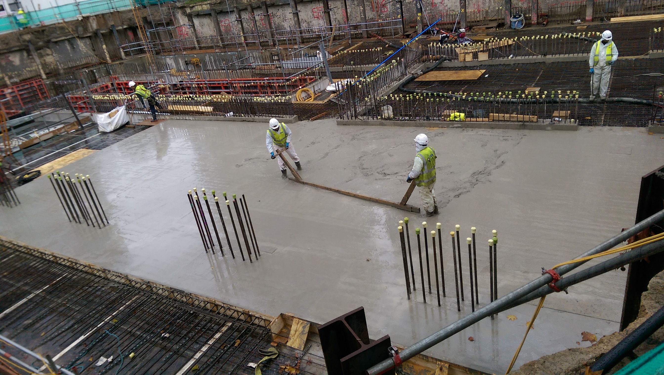
On Wednesday we did our first large(ish) concrete pour (225m3). This was for the basement raft and 2 pile caps. The aim was to fill the 2.1m deep raft (large pile cap) to underside of slab which will be formed across the entire site (450mm thick, to be cast in waterproof concrete). The setup was a mobile pump at the end of our pit lane which involved having concrete wagons back onto the pump. Luckily the front of the vehicle was far enough away from the road to avoid any road traffic accidents.
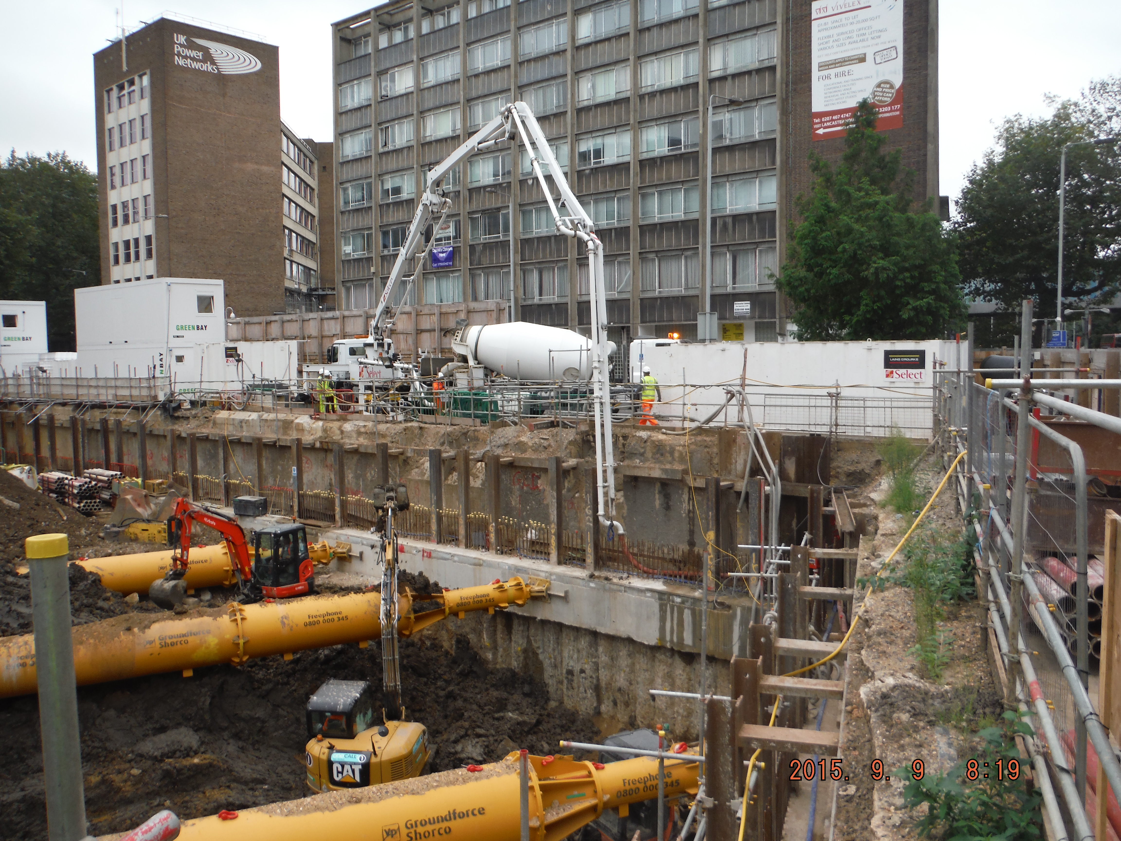
Pump positioned within the site, concrete wagons backing onto it, just into site. The pipe line then ran around along the capping beam and down to the pour location.
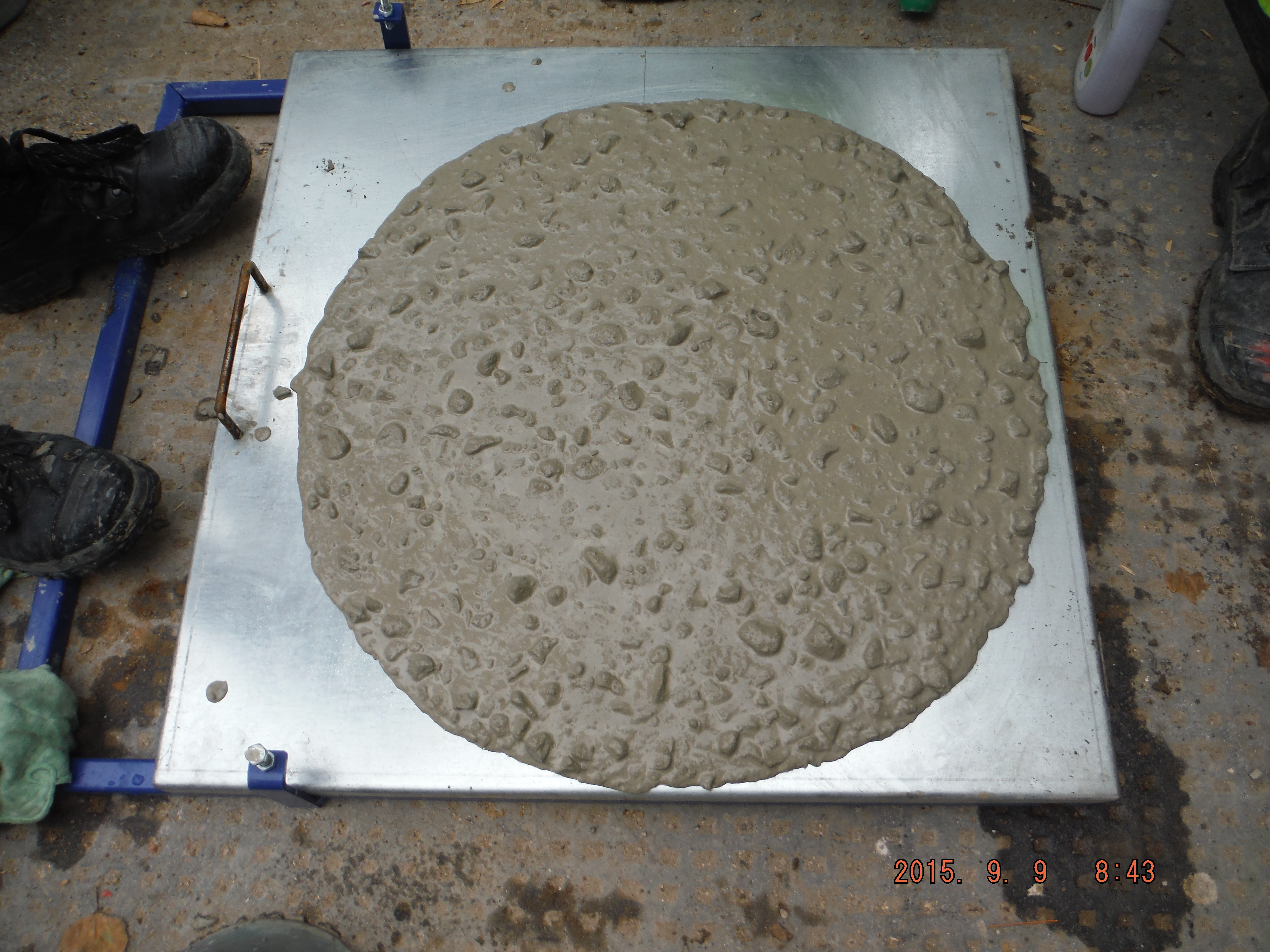
F5 consistence – therefore flow table tests. Interestingly the test was repeated after 4hours and it achieved just a 20mm lower radius.
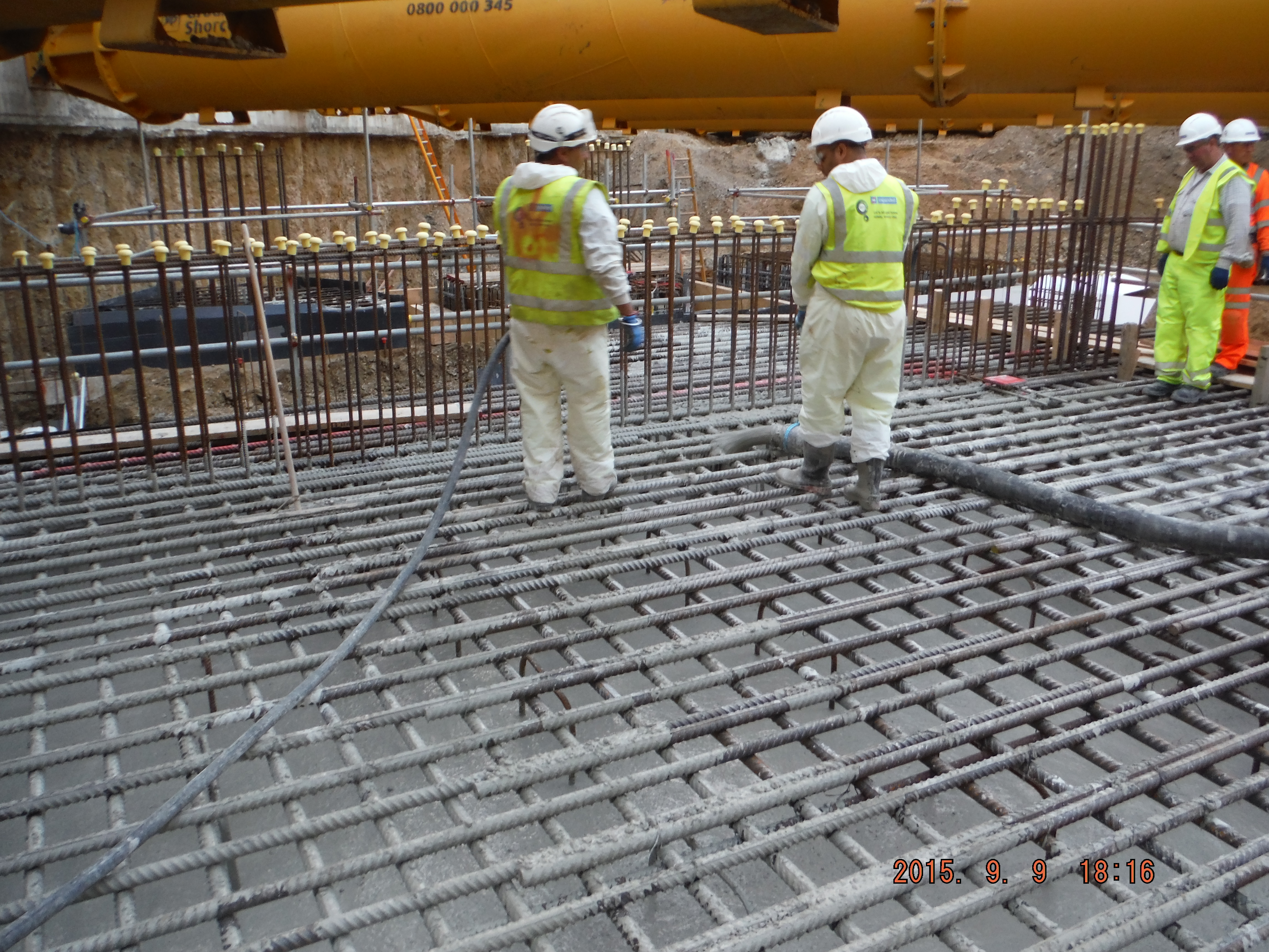
Pour was to underside of slab level, which is about 400mm below the height of the reinforcement shown. Before the concrete is fully cured it will need to be removed from the rebar.
Overview of raft pour – see wall starters to negotiate when curing.
Next day thermal shrinkage cracks. The hope is that when the slab is cast on top it will have fewer cracks because it is only 450mm. Additionally, it will contain a waterproofing additive to prevent water ingress.
Quality Assurance
The quality assurance process involved taking flow tests of the wagons every 5 vehicles and cubes every 50m3. Each delivery was checked for the mix and the details recorded on the pour history sheet (mix, batch times, location of where the concrete ended up). The idea being that should a random concrete wagon arrive at our site we would spot it. Amusingly, one of our wagons ended up somewhere else who were not using quite such a stringent checking process!
There was a drained cavity sump within the pour which had to be in waterproof concrete and so this was poured using a hyrib stop end with the last pour of the day/night.
When we come to do the slab the final finish will be an epoxy floor coating, the concrete slab will be shot blasted to give it grip because it is a car park. Coming to our part in this plan, the slab will need to be cured. There are two common methods:
Polythene and spray on.
Polythene
Advantages: Quick to apply, logistically not too difficult to put in place (polythene rolls are not heavy), 100% moisture barrier (assuming all sides are fastened down),
Disadvantages: Protrusions such as wall starters, polythene marking the slab, mitigated by keeping the polythene sheets as flat as possible, and tearing is likely.
Curing agent
Advantages: Pretty cheap and not difficult to apply.
Disadvantages: It is time consuming to apply, a sprayer is needed, ensuring complete coverage is difficult because it is not easy to see where it is applied. It is not an impermeable membrane so there will be some evaporation.
Recommendations
Polythene, if applied correctly is likely to give a better method of curing because of the 100% moisture barrier. The difficulties in our case of fitting it around wall starter bars can probably be overcome by fastening it either side of the protrusion.
Anyone any experience/views on the matter? What do they do in the US/ Australia for curing slabs?
