Archive
Site Two Fifty One – Environmental Problems
Site Two Fifty One – Environmental Problems
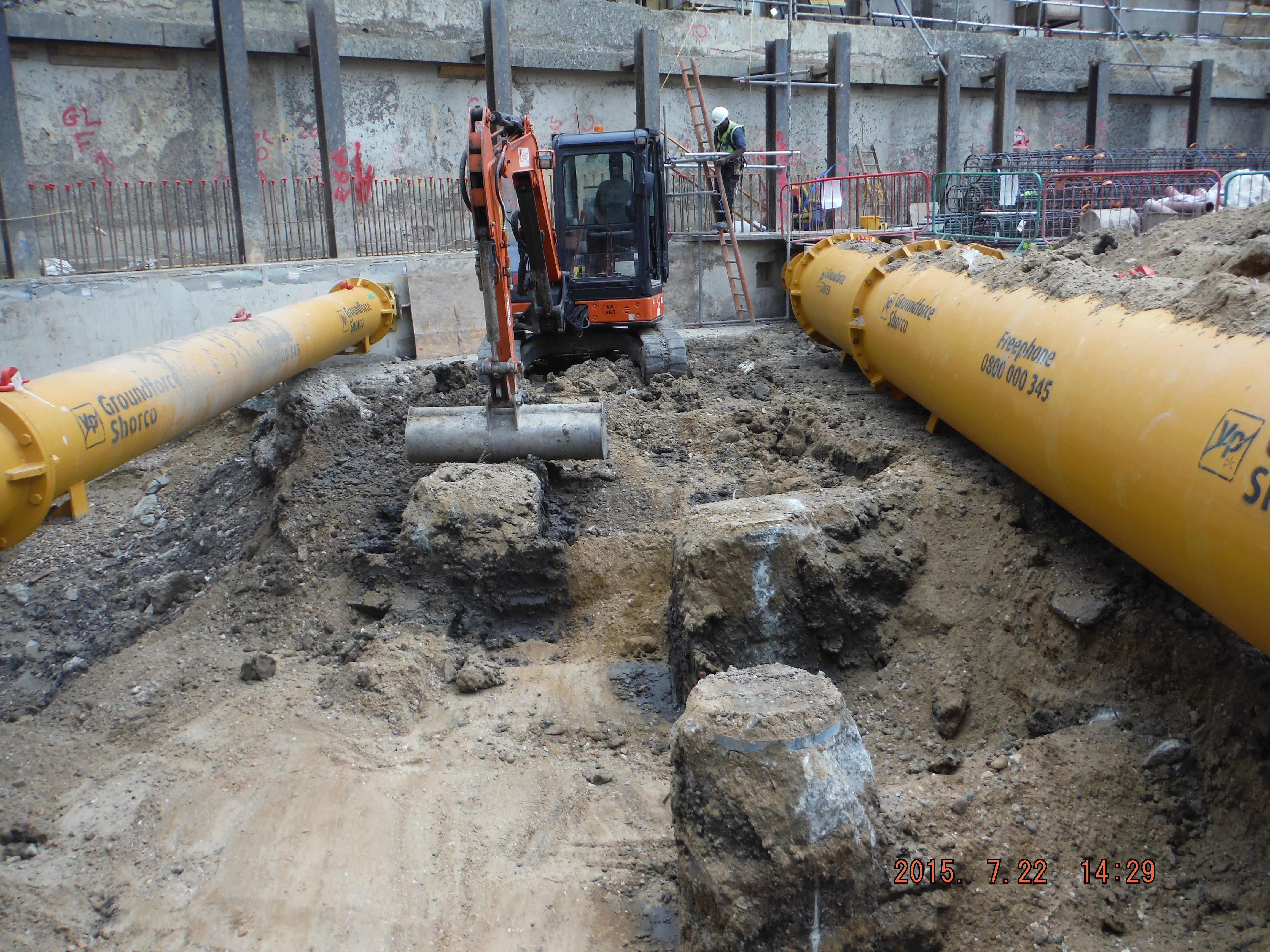
During the removal of spoil from Two Fifty One to enable the installation the Groundforce props some of the lorries of muck were rejected from the tip because they smelt of diesel. I had no record of a diesel spillage on site so it all seemed strange. The loads had to be returned to site because the tip was refusing to take them and the carrier (Erith) were not able to dispose of them. Typically as the excavation progresses it becomes harder to separate/segregate anything. Therefore having excavated material returned to site is somewhat of a problem.
Contaminated material being stored left of the ramp access into site.
On further inspection of the area the muck was being excavated from it was identified that some of the sand and gravels had turned grey. I.e. it contains diesel.

The photos show the grey streak in the sand and gravel showing the diesel contaminated ground.
Aside from the fact that the majority of the area had been excavated and loaded onto tippers (albeit to then be returned to site) it was clear where some of the more affected areas were which should help reduce the spread of contamination.
So what?
The extent of the problem is just getting started (no environmental agency involvement yet) and as it has happened and now stopped, typical actions – such as using a spill kit/isolating the source are redundant. Therefore I have highlighted some of the post incident considerations we are currently going through.
- Stop sending muck away from the site (significant impact on programme as the key task is to remove muck at this stage).
- Identify what the contamination is. Initially, this will be done by using a Photo Ionization Device – this gives a rough and ready level of volatile organic compounds in the sample. Below 50 parts per million is apparently acceptable. You don’t need much diesel to make things smell of diesel so I am hoping that is the case…
- Record/report the incident, brief the site team on the importance of reporting spillages.
- Once we know the extent and type of the contamination the loads can be removed. Worst case the muck will be removed as hazardous waste at £1700 per load which comes with permits to move hazardous material. We are paying about £200 at present so that would have significant commercial implications!
- Attempt to keep to schedule with a mini-mount Everest forming in the corner of the site!
More widely here is a brief update on drainage and reinforcement installation.
Drainage.
We have just started to install below ground drainage in the Basement Level 2 raft slab. We are using the Saint Gobain timesaver inspection chambers and Ensign pipes. For future reference, Ensign is a significantly lighter product, more easily moved/handled and costs much less (we have made a circa £30K saving by requesting to use the lighter system).
The drainage is being installed within the area between the bottom and top mats of reinforcement.
What I wish I’d known:
- Testing methods – something about bungs, and air bags. More to follow when I understand what that is.
- That a foul gully run cannot rapidly change gradient in a run because the solids will separate out.
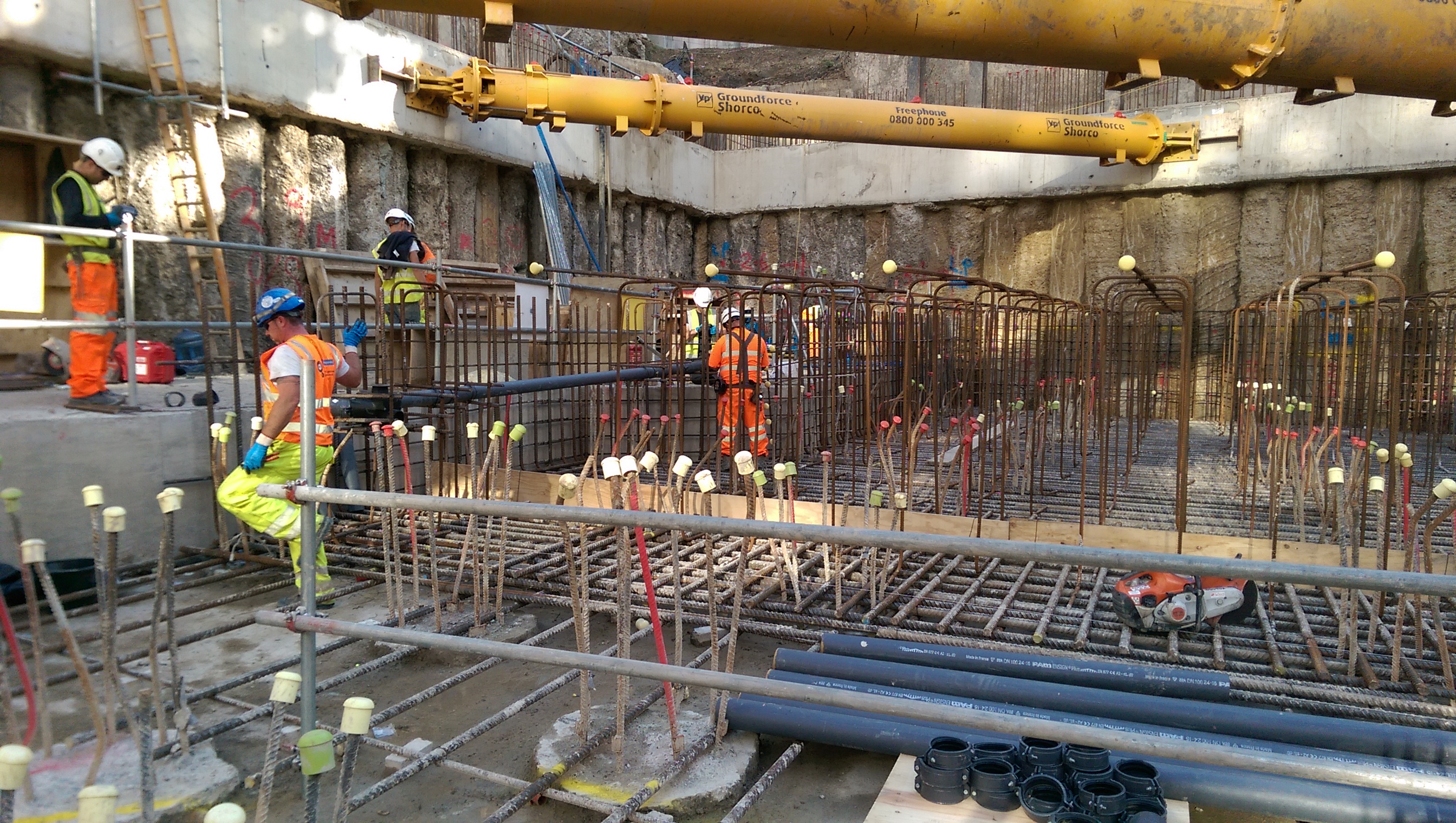
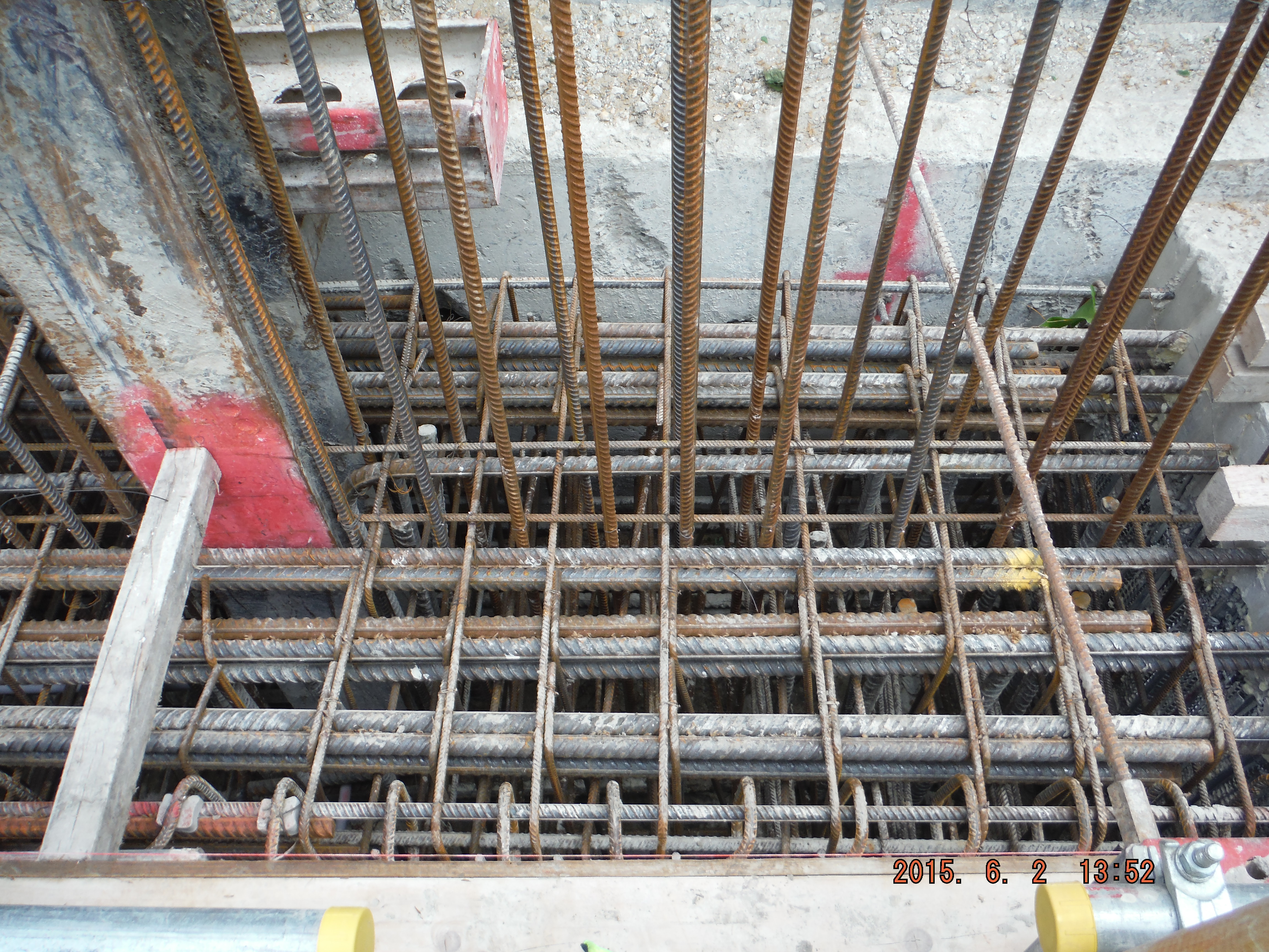
Basement Raft.
The 2.1m deep raft foundation is currently being constructed. It is quite an impressive site seeing 40mm, 12m long bars being positioned by hand.
Raft bottom mat reinforcement being installed.
The original aim was to use Pecafil formwork (permanent sheeting) for the concrete pour. Due to the number of piles this is proving a little more complex. As the ground is excavated, pile reinforcement acts a bit like dragons teeth preventing easy access to return to backfill around the raft. The plan is continuing with the idea to use a small dumper to move material back into position, rather than switching to the use of shuttering. Again, more to follow on the success of this plan!
A final thought:
There is a slab (450mm) which will be poured across the site, including on top of the raft making a total of a 2.1m deep foundation.
There is a bottom mat to fix in the raft and a top mat to fix in the slab.
Would you, a) fix the bottom mat, pour the concrete raft then fix the top mat and pour the slab? Or, b) fix bottom and top mat, then pour raft, then pour slab (i.e. do pours with all steel fixed)?
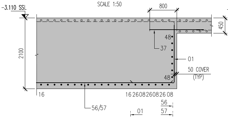
Raft foundation comprised of 450mm slab and 1650mm raft.
Site Two Fifty One – Time, cost and quality
Site Two Fifty One – Time, cost and quality
This week at Two Fifty One I seemed to be more directly involved in the time, cost quality triangle and so I thought I would highlight a couple of simple examples to demonstrate.
Commercial background.
The commercial arrangement on site Two Fifty One is that the project is to be run on a negotiated design and build contract. Having agreed a lump sum price to the client of £119M, except for provisional sums, the contractor: Laing O’Rourke, is obviously keen to build it for less to make a profit.
How does this affect me on site?
This week another capping beam pour took place, while a health and safety advisor was visiting and while the drainage order was being finalised.
Cost.
In reverse order, the drainage order included consideration of the attenuation tank which is to be situated below the basement level 2 slab. Company 1 was specified by the designer (or an approved alternative could be applied for) and therefore almost without question Company 1 were to be used. The QS team then got involved and got a quote from Company 2. A series of reasonably sensible RFIs from the designer followed (focussing on maintenance and strength of tank to resist earth pressures) and time started to disappear. Company 1 were informed about a second competitive quote and reduced their price. This meant that by simply asking the question of Company 1 they reduced their price saving a few thousand pounds.
Lesson Learnt? So other than saying it’s obvious to get a number of quotes, it is perhaps less obvious but equally commercially important to recognise when to challenge an expensive design, especially in a design and build contract. These smaller sub-contract packages are actually pretty key in the Design and Build contract arrangement. So far there have been about 10 sub-contractor packages ranging from sheet piling to attenuation tanks to concrete waterproofing supplier. So clearly a bit of effort getting quotes/bids from the market lots of cost savings can be gained from that which the initial project tender was based on. I here Steve’s bus…
Health and Safety/Quality.
Next comes the health and safety advisor’s visit. On a difficult day with machines breaking, particularly low consistence concrete (to gain high early strength) making pours difficult, a 5m deep excavation confining the site further and a muck away lorry to be loaded every 15 minutes, managing every activity was challenging.
This photo shows the ever decreasing space on site with muck away lorries needing to be loaded effectively non-stop all day.
Props reducing site space

Crane at maximum reach.
Of the issues that could have been raised, the main one was access.
To get the formwork shuttering ready for the pour the focus had not been on access. When pointed out it is obvious and I suppose the lesson is: there are a few basics that must be correct and access is up there. The photo below the walkway barriers leading towards the concrete pour. It does not show that the walkway just ends in a 1m drop meaning the operatives had to scramble down the bank.
Barriers with no access at the end!
Time.
The capping beam has to be completed to be able to dig down. In order to do this the concrete strength within the capping beam must be greater than 30N/mm2. This would have been fine but due to a slow exit of the piling team we are on catch up.
So what? Capping beam pours have been completed and props installed shortly afterwards. With over 10,000m3 of sand, gravel and clay to be removed from the site the emphasis is on digging, i.e. loading the props and therefore loading the capping beam. In short, the time for the capping beam to reach 30N/mm2 has reduced from a few weeks to a few days. To solve this there were numerous plans to crush more cubes, do temperature matched curing and place thermocouples within the capping beam to assess in-situ strength. However there was no time to see what might happen/work, so the mix design was altered to attempt to get a quicker strength gain. (So much for previously trying to avoid cracking!)
Mix design alternations focussed on the cement content.
Original cement content: CEM 1: 135kg/m3 with GGBS: 315kg/m3.
High early strength concrete: CEM1: 405kg/m3 with GGBS: 45kg/m3.
Wowser! You could have fried an egg on the concrete. Basically the high cement content produced a very high early strength (about 41N/mm2 within 7 days). So despite there being a cost for the higher cement mix the key driver was time in order to get the excavation going, and therefore multiple work fronts to attempt to regain lost time.
Capping beam fully loaded by props. Excavation needed to get going to prepare ground for raft slab pour.
Summary.
Every step of the way in the project revolves around time, cost and quality. I had a reasonable argument with the QS team saying that rather than faffing about getting quotes from everyone endangering getting items ordered in time, the focus should be on constructing the building. But then if the building costs more than £119 there will have been no point doing it for the contractor. So it seems the way forward is within the triangle, perhaps being at different corners at times, but it is a balance of time, cost and quality that is the key, which I think is wrapped in the word sustainable.
Site Two Fifty One – Problems, drainage and digging
Site Two Fifty One – Problems, drainage and digging
After the jubilation of completing the piling last week, and the removal of the rig on Friday night, a nightmare awoke the site today.
One of the tower crane bearing piles was piled in the wrong place. Coordinates were used to set it out and a typo of a 2 rather than a 3 mean the pile is 10m out.
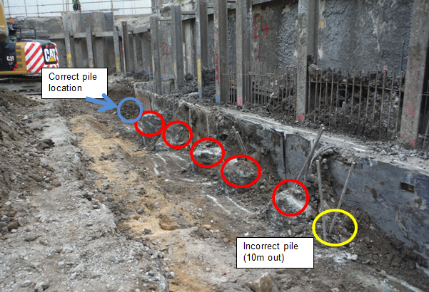
Why – it was a simple typo but where was the gross error check to double check it was in the right place?
The dywidag bars that project out of the ground were / should have been a bit of a giveaway. The person who set it out was a junior trainee student on attachment under the umbrella of the Site Engineer and myself.
So what?
The piling rig has left and the tower crane foundations, grillage and design all need cat 3 checks (due to proximity to Network Rail) which have taken weeks to organise. The problem of what to do now also needs to be resolved.
Options.
I can’t proffer the solution other than to say options include:
- Redesign of the tower crane foundation using the piles that have been installed – unlikely to work as they were on the limits anyway. If something can be made to work and get around the eccentric loading this would be the least expensive option.
- Bring back the piling rig. This would be a phenomenal cost and time.
- Bring in a smaller piling rig to drill some piles to replicate a 750mm 24.5m deep pile. Costly but practical.
- Others. Announce the problem far and wide and hope the corporate engine of Laing O’Rourke can find a better answer.
Drainage
How do you go from a drainage layout plan to installing drainage runs?
Design, resource, construct. The design is done and construction seems to be within people’s competency. That leaves resourcing. The drainage supplier has not sent us a very good quote, leaving more questions than answers. Saint Gobain are the manufacturer of choice who have been helpful but that only goes so far.
Then other issues like where do the drainage points (vent pipes, gullies, drain points, etc) actually sit arise. Ask the designer (Waterman) and they refer you to the architect. So lengths, angles and connection pieces become unclear.
Gully points need a grate, p trap, extension piece, bend and connectors. No problem until the grate specified is and L15 strength which I think means able to carry a stress of 15kN/mm2 based of the picture below, fine for pedestrians but this is for a car park. That makes me wonder if the trap system underneath is sufficient.

Aco Drainage Load Class Table http://www.acobuildingdrainage.co.uk/about-us/load-class-table.aspx
It is likely I am over complicating things but this does not seem to be as straightforward as it should be.
Digging
The site excavation continues with the London Clay now appearing at about -4.5m AOD. A bit higher than expected… repercussions include greater skin friction perhaps, less value to be gained from excavated material. The dewatering has not been too much of an issue using the approach of dig, dewater, dig, dewater.
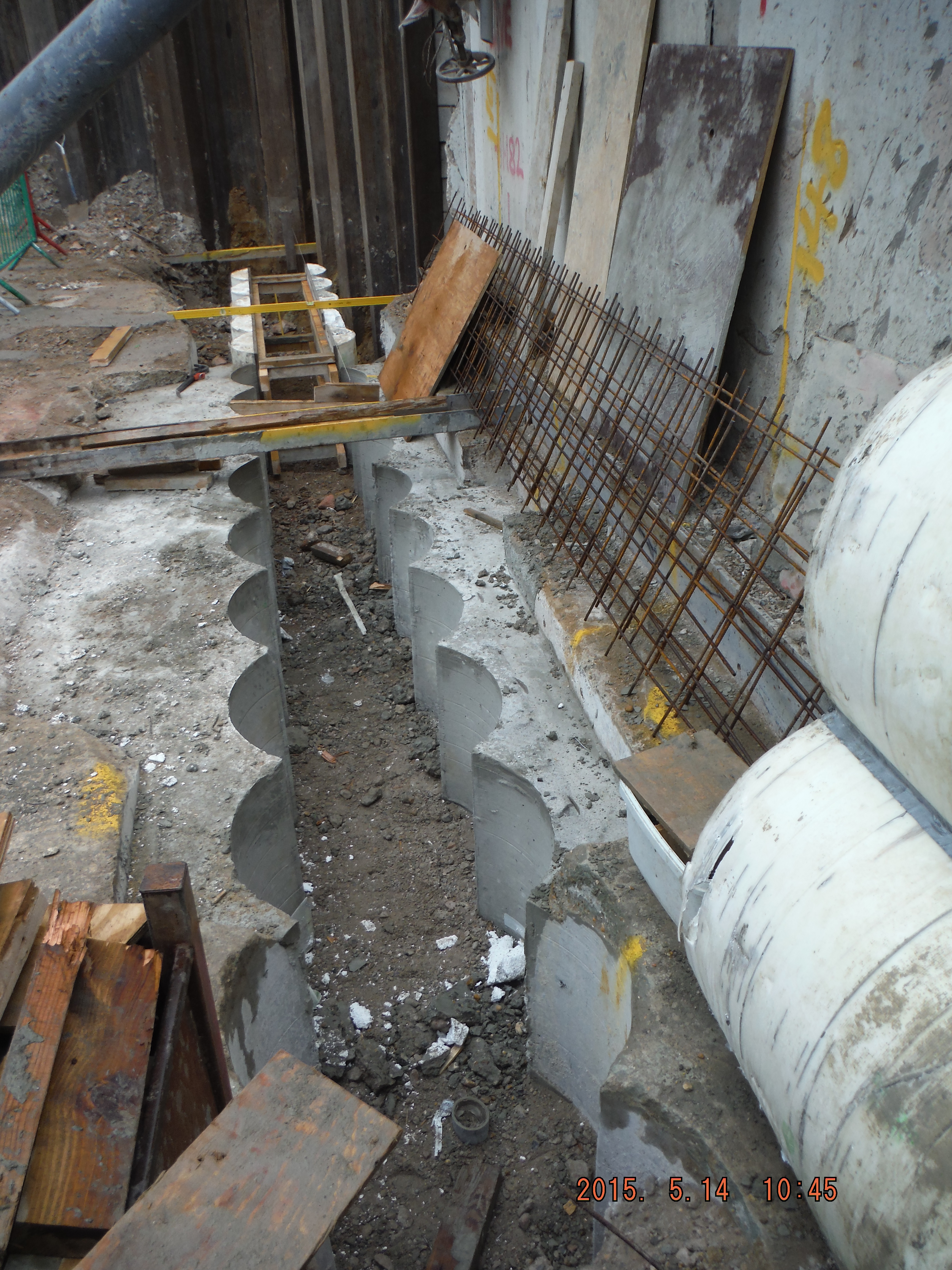
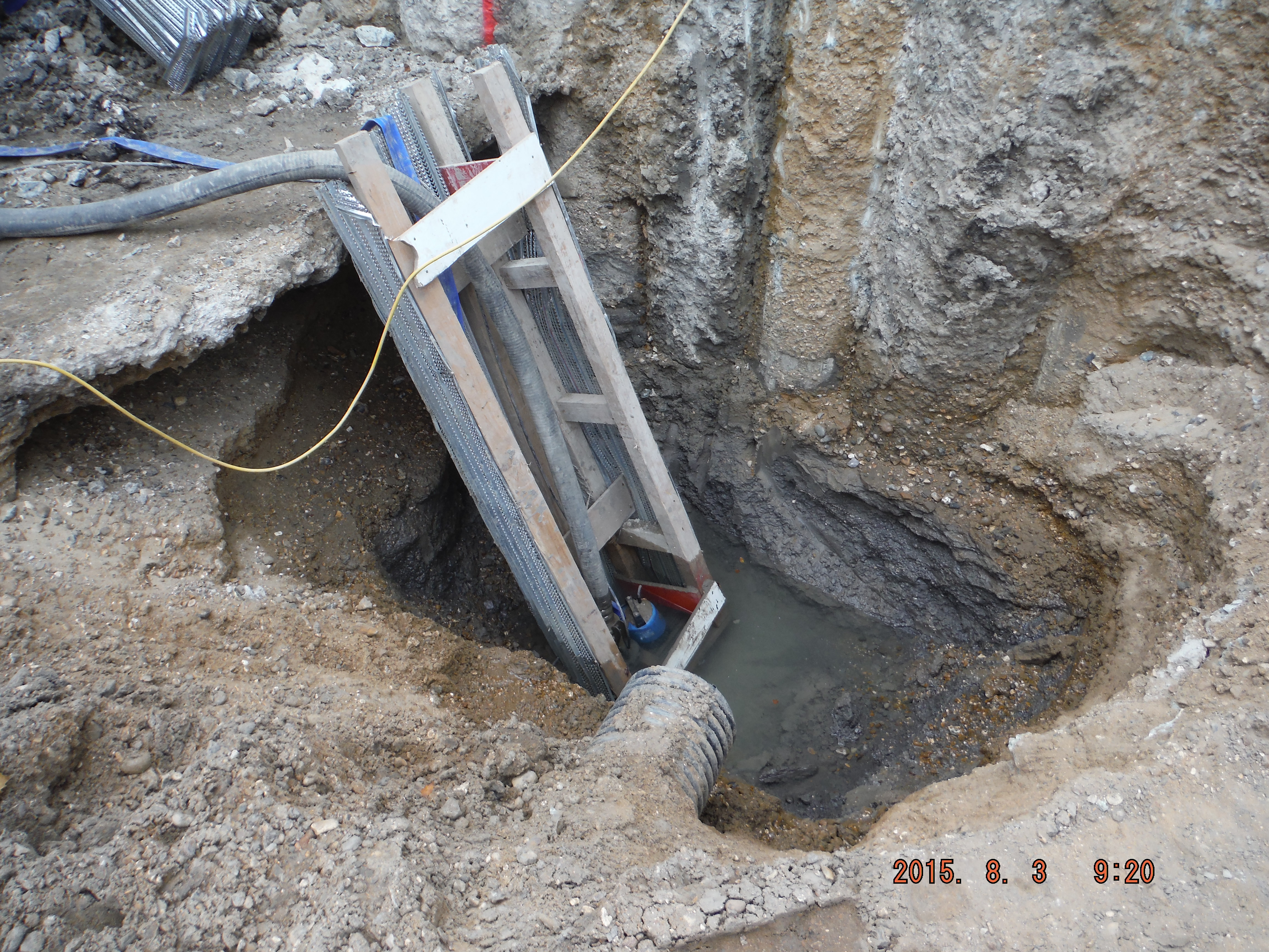
However revealing “interlocking” secant piles is starting to show that perhaps they were not as locked as hoped. Either that or the very damp patch is being caused by something else. A few photos of the progress of installing the props.
Note bearing piles have to be broken down in order to install the props. The excavation then continues to depth and then the protruding piles are snapped because the reinforcement cages have been plunged to cut off level.
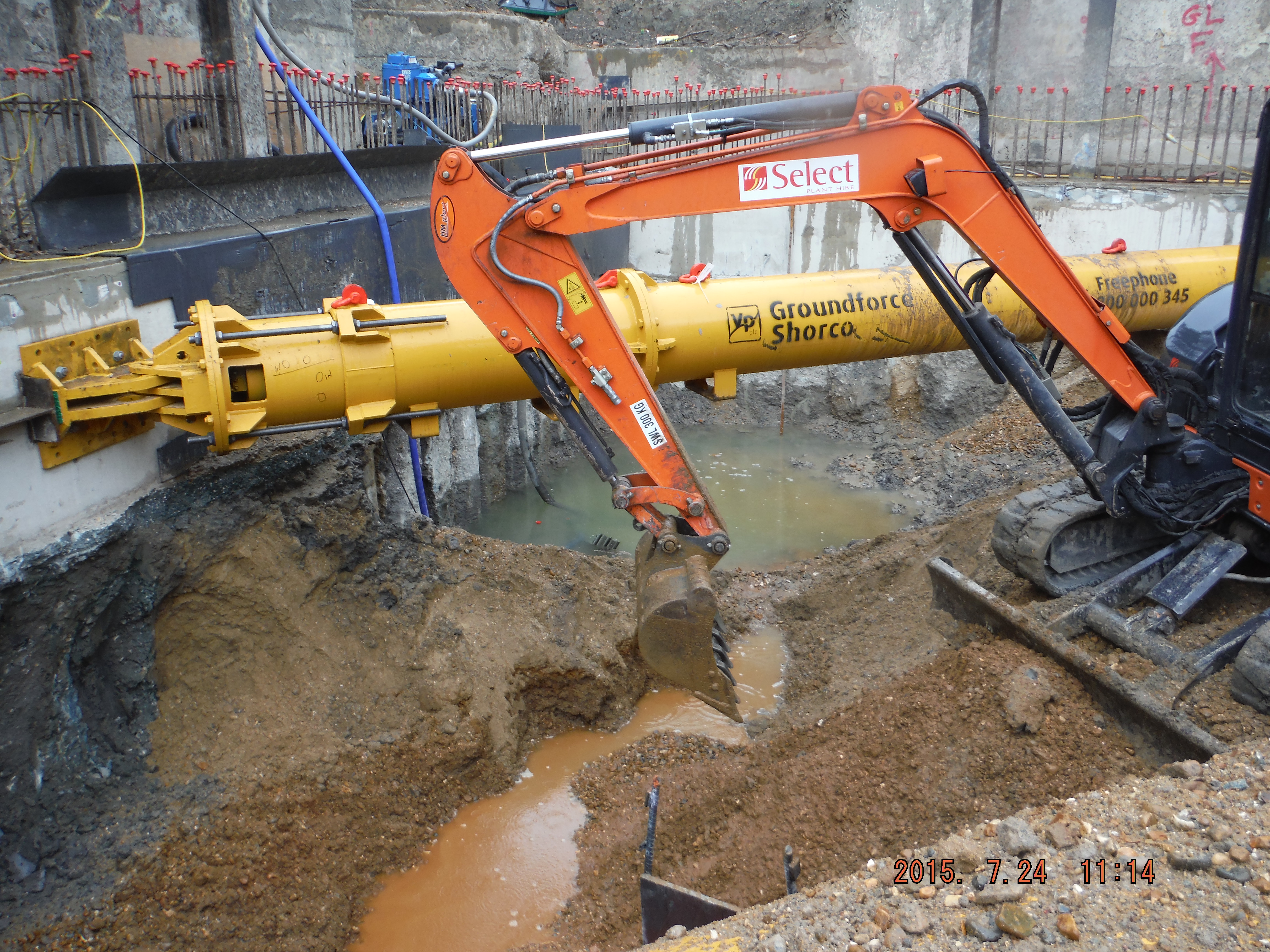
Ground water (and plenty of rain) pooling in the corner ready to be dewatered.
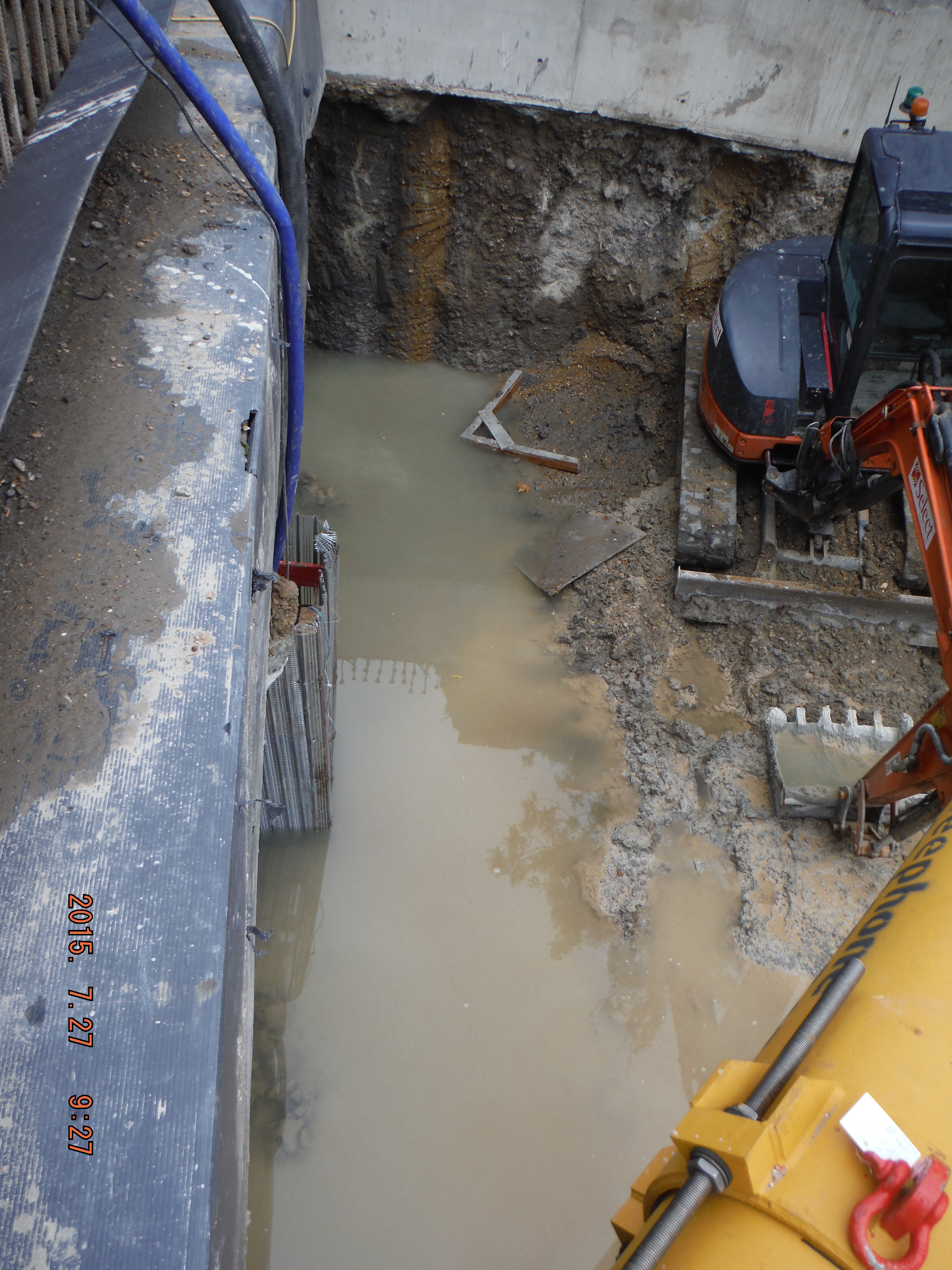
2 inch electric pump and 3 inch diesel pump used to remove water.
Pumps submerged within sump at bottom of excavation (close-up)
Pumps submerged within sump at bottom of excavation
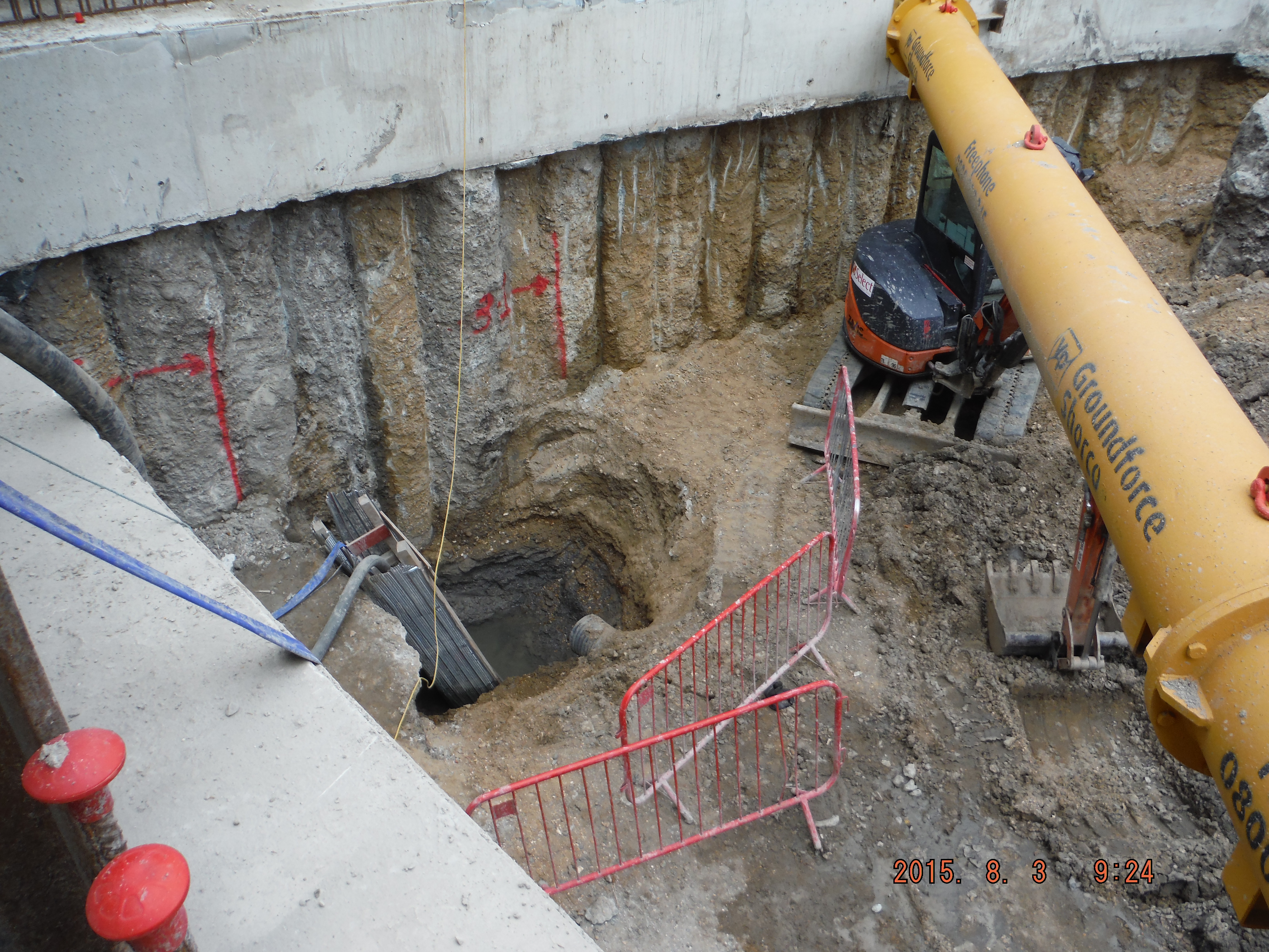
Mass excavation (reduced dig) in order to install next prop.
Mass excavation (reduced dig) in order to install next prop.
CPD/ UK Spec Attainment – Science, Technology, Engineering and Mathematics Network (STEM)
CPD/ UK Spec Attainment – Science, Technology, Engineering and Mathematics Network (STEM)
A way of achieving ICE attribute 9 – Professional Commitment, is to promote engineering (sub-attribute 9D “Demonstration of appropriate professional standards, recognising obligations to society, the profession and the environment”. I suspect the IMechE and IET have a similar requirement under the UK Spec.
One way of doing this is to use the Science, technology, engineering and mathematics (STEM) network.
This is a nationwide charity which has links to schools and groups for STEM Ambassadors to visit and talk about all things STEM (or specifically engineering in our case). The process involves getting a Disclosure and Barring Service certificate (newly named CBR check to be able to work with under 18s) and attending a 2hr induction. I am blogging because I have just attended an induction which was pretty useful because my baseline knowledge was low. I have included a brief summary of some of the points for those thinking this might be an interesting route to take…
There are 4 principles to adhere to for a STEM activity:
- There must be benefit to students
- The subject delivered must be STEM based
- Non-supervisory
- Voluntary
The STEM network has a database which works two ways. If you have something to offer schools you can highlight your skill and teachers will respond. Alternatively, teachers will request ambassadors to visit and deliver a talk/activity/lesson.
The ICE has lots of resources to assist and there are case studies which can be used for inspiration for lessons.
A constant theme was understanding why you want to be a STEM Ambassador – most people either said to promote their subject to inspire young people or to get more women into the subject. Otherwise the general position was that people were enjoying working in a STEM area and were keen to pass on their enthusiasm to a younger generation.
Thoughts
This approach (using STEMNET) is not the most original and I was not the only student in the room there to demonstrate ability of an ICE attribute, but actually it looks like a very sound way of promoting engineering to young people. That is something I felt my school did less well so it is interesting (to me at least) there are now even after school engineering clubs!
The audience was perhaps the most diverse I have ever seen: old, young, male female, mixed religions, races, languages, you name it. The spectrum of people being inducted as STEM Ambassadors was so varied (head of IBM equality and diversity to a student who wanted to promote how to make computer games) that aspect alone provided interest in itself. That is part of STEMNET’s approach to breaking down stereotypes – refreshing.
In a growing industry, at least while the economy is on the rise, it seems an ideal time to promote engineering to young people.
https://db.stemnet.org.uk/register
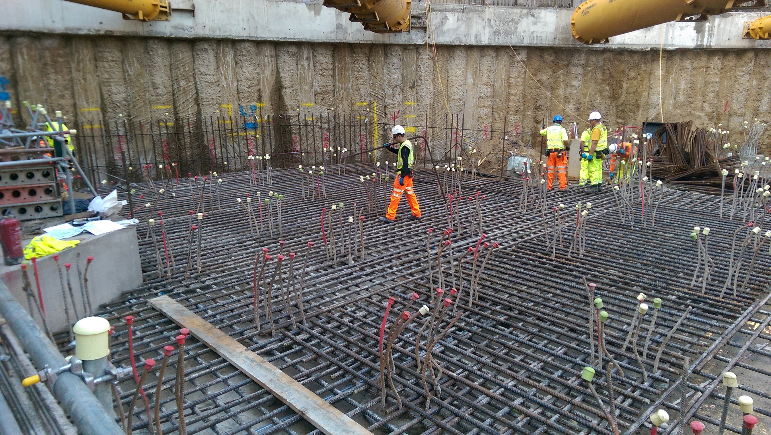
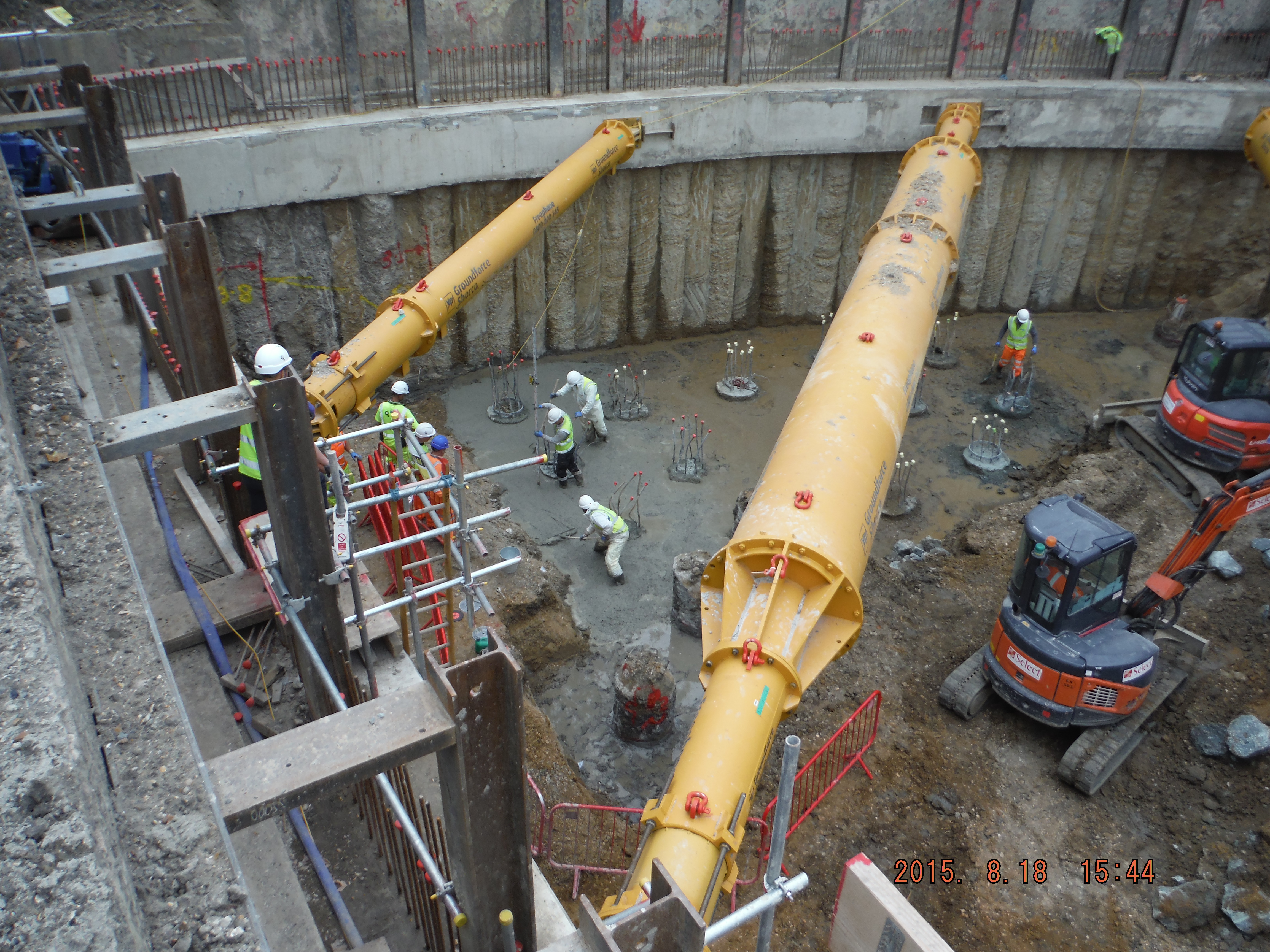
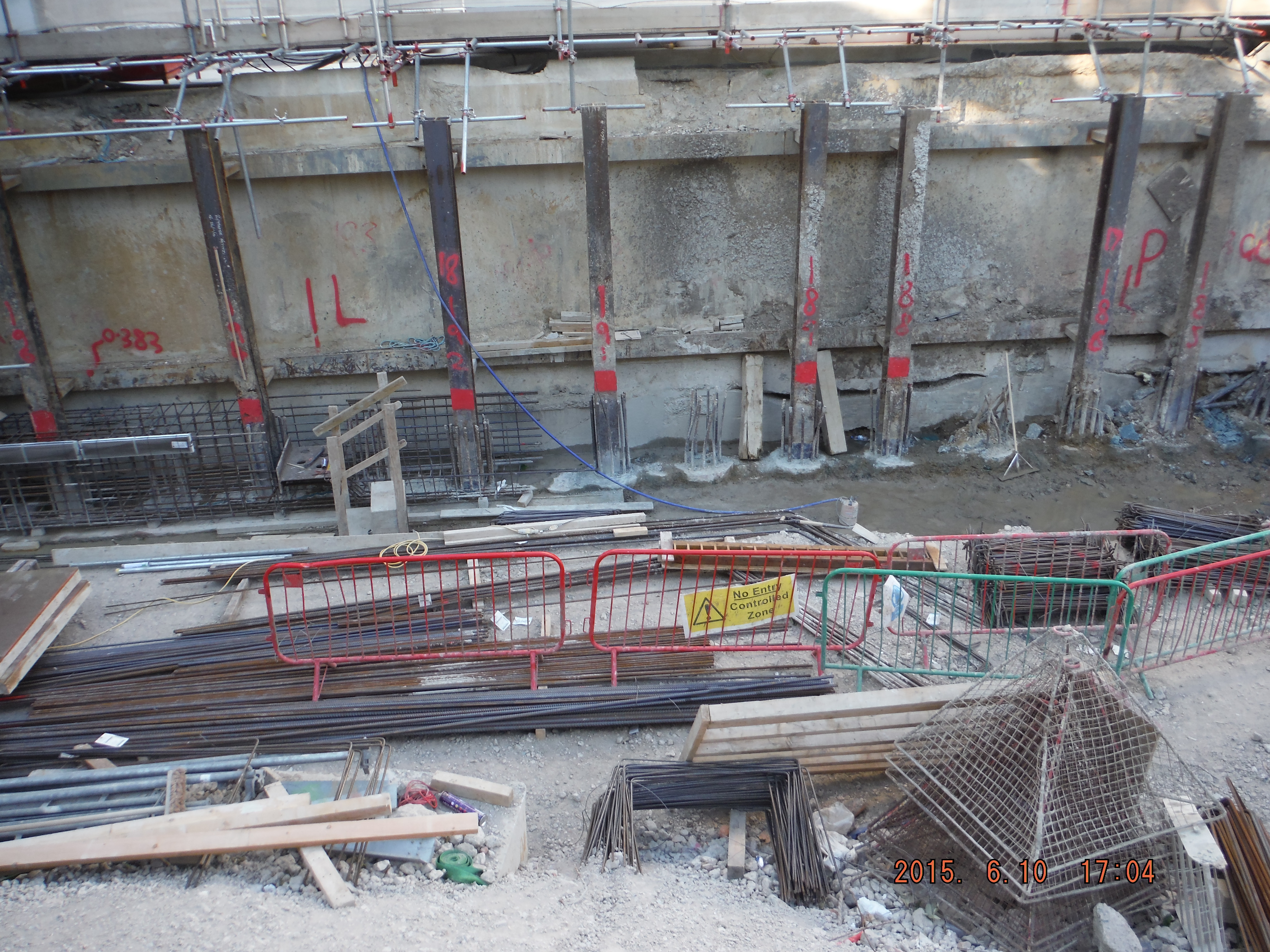
Site Two Fifty One – Prop Installation
Site Two Fifty One – Prop Installation
Despite site activities being focused on the remaining piling works (17 CFA piles to go), as always there is a push to do multiple other activities all at the same time, but luckily not quite in the same place.
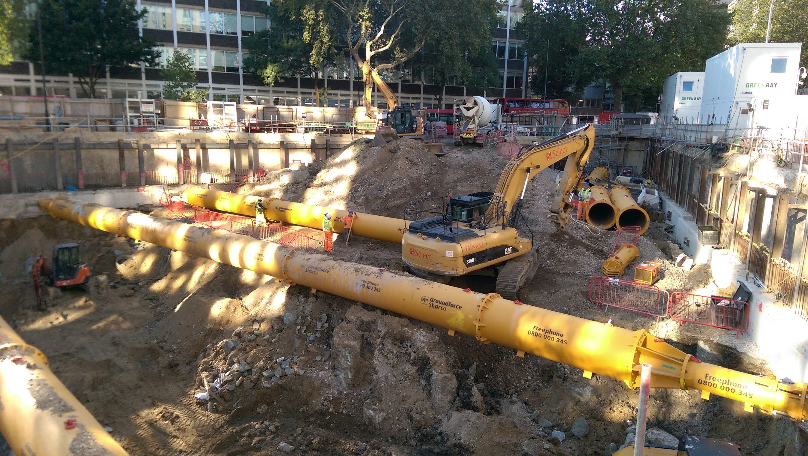
Groundforce Shorco prop installation. The aim is simple – put in 9 props and remove about 1500m3 of water and about 10,000m3 of sand and gravels (and some clay).
Prior to now sections of capping beam have been poured, shear stubs were embedded and prop end plates were fastened.
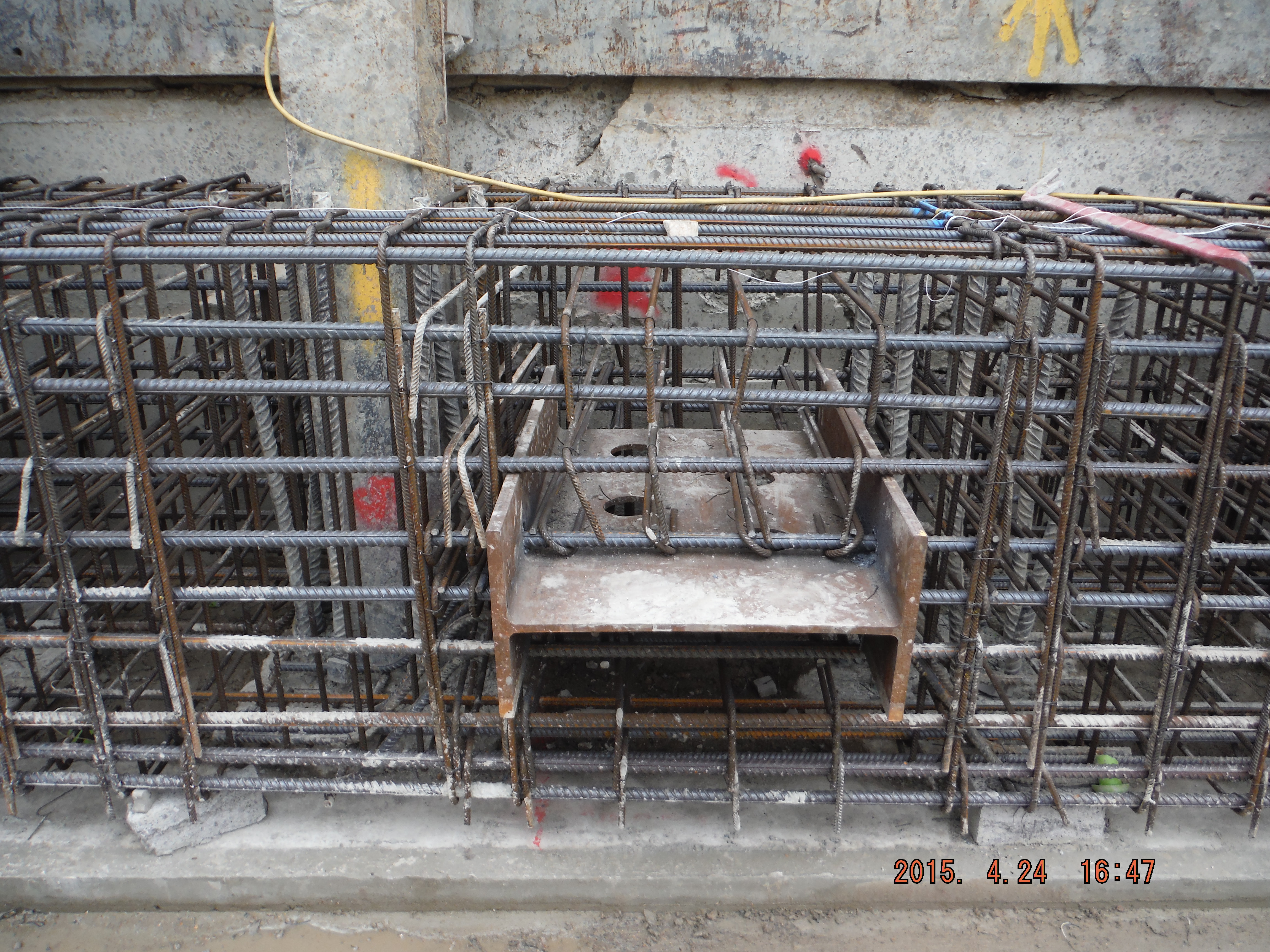
Shear stubs installed
End plates being fastened to the capping beam
The general principle is to excavate to underside of capping beam, install a prop, excavate in order to dewater, excavate more, dewater more, install the next prop and repeat, 9 times (9 props), all while avoiding piles and segregating the exceptionally beach like sand and gravels (removal of this is less than half the cost of clay muck).
The first 2 props were installed this week and aside from problems with crane time there are a few other interesting points to consider.
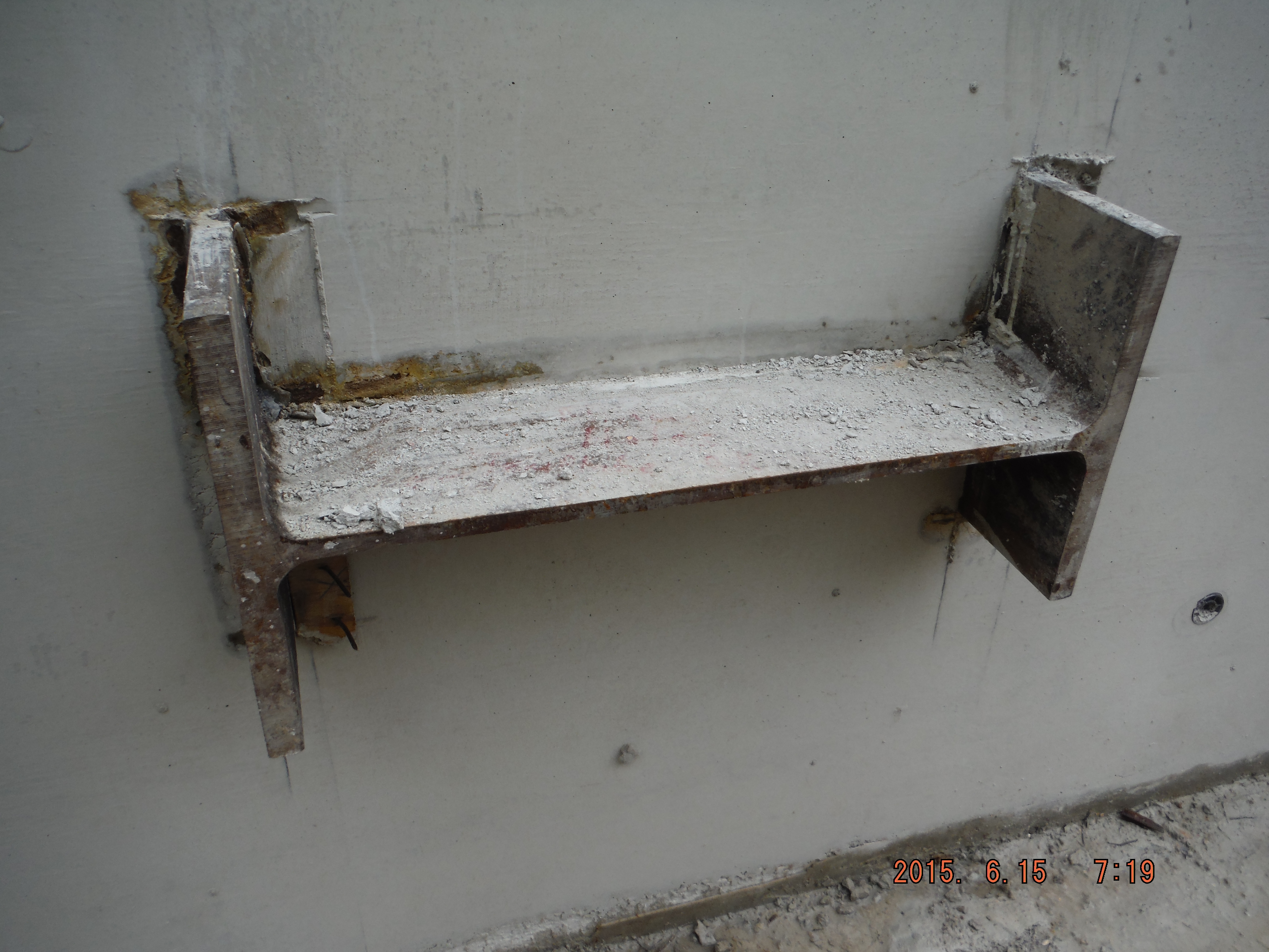
Problem 1. End plates not meeting with shear stubs. Despite very careful installation of the 4 x M30 bolts embedded 250mm into the beam using resin, the end plates did not quite have full contact with the shear stubs. Options: weld a connection, use a grout pack, place shims or do nothing (assuming with the applied prop pre-stress the gap would close) to provide a load path. A good weld is difficult to achieve in a 30mm deep recess and the plates may well be damaged when the weld is ground off at the end of the works. Using a grout pack is possible but with movement of the prop (thermal expansion in the day) this might crack. Shims – the best and simplest option – this was chosen and on referral to the designer, the recommendation was to use S275 steel.
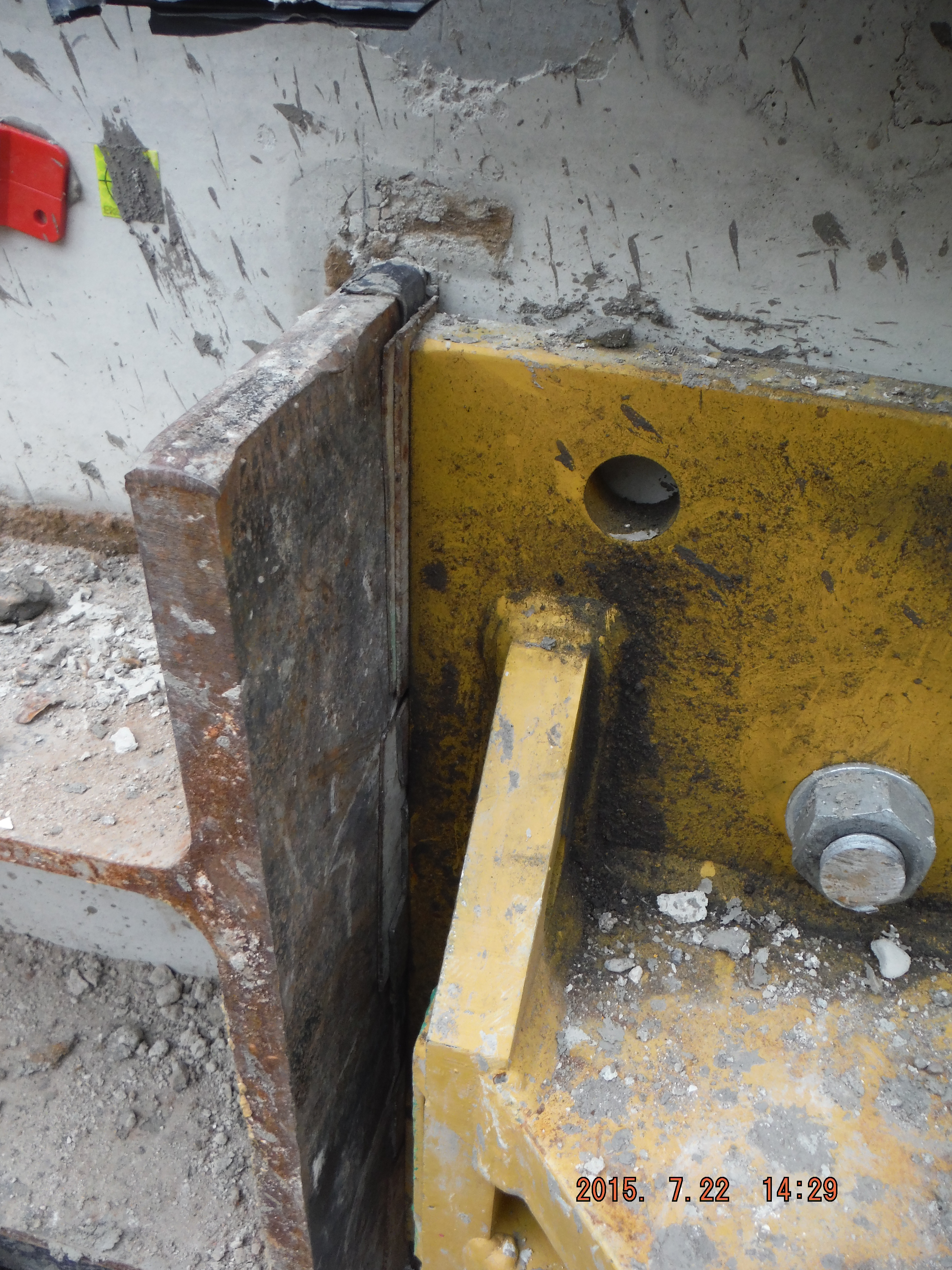
Shims used to provide path for load transfer
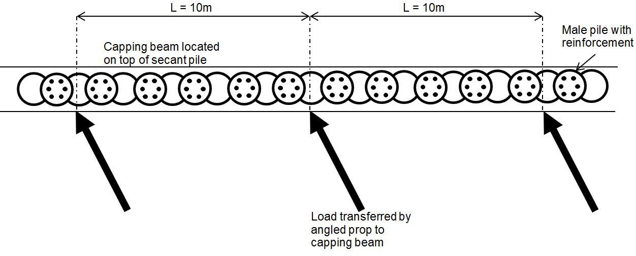
Problem 2. Not all of the capping beam is complete. The capping beam (which will form an entire ring around site) is used to transfer vertical load (from the buildings above) to the piles below. It is also being used to prop against horizontally.
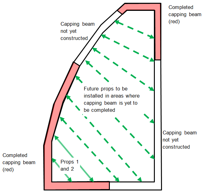
Diagram shows line of completed capping beam (in red) with future props to be installed (dashed green arrows) in areas of capping beam yet to be cast.
The question is, is lateral load transferred along it (as if it were a steel beam) to the ground at the corners or to the secant piles below acting in a sort of individual cantilever/domino fashion. The secant piles have 900mm of reinforcement cage embedded into the beam and are at 1.2 centres with male C30/40 piles and alternate C10/15 female piles. On further consideration, the female piles are only there to provide water resistance, so the load is transferred into the top of each pile down into the ground (embedment anything up to 23m for the permanent condition).
This can be modelled as follows:
Plan view of capping beam showing prop loads applied to beam
By splitting the capping beam into sections around the props (10m spacing between props in this case) each pile within the section can be considered to carry part of the prop load. It is proposed the nearest two piles will see more load than the next two and so on. If each prop and pile section behave in this way it implies that as long as the capping beam is completed to at least midway between the next prop the system should work. That’s the theory anyway!

Plan view showing prop load transferred horizontally and vertically into the capping beam and onto the male pile reinforcement

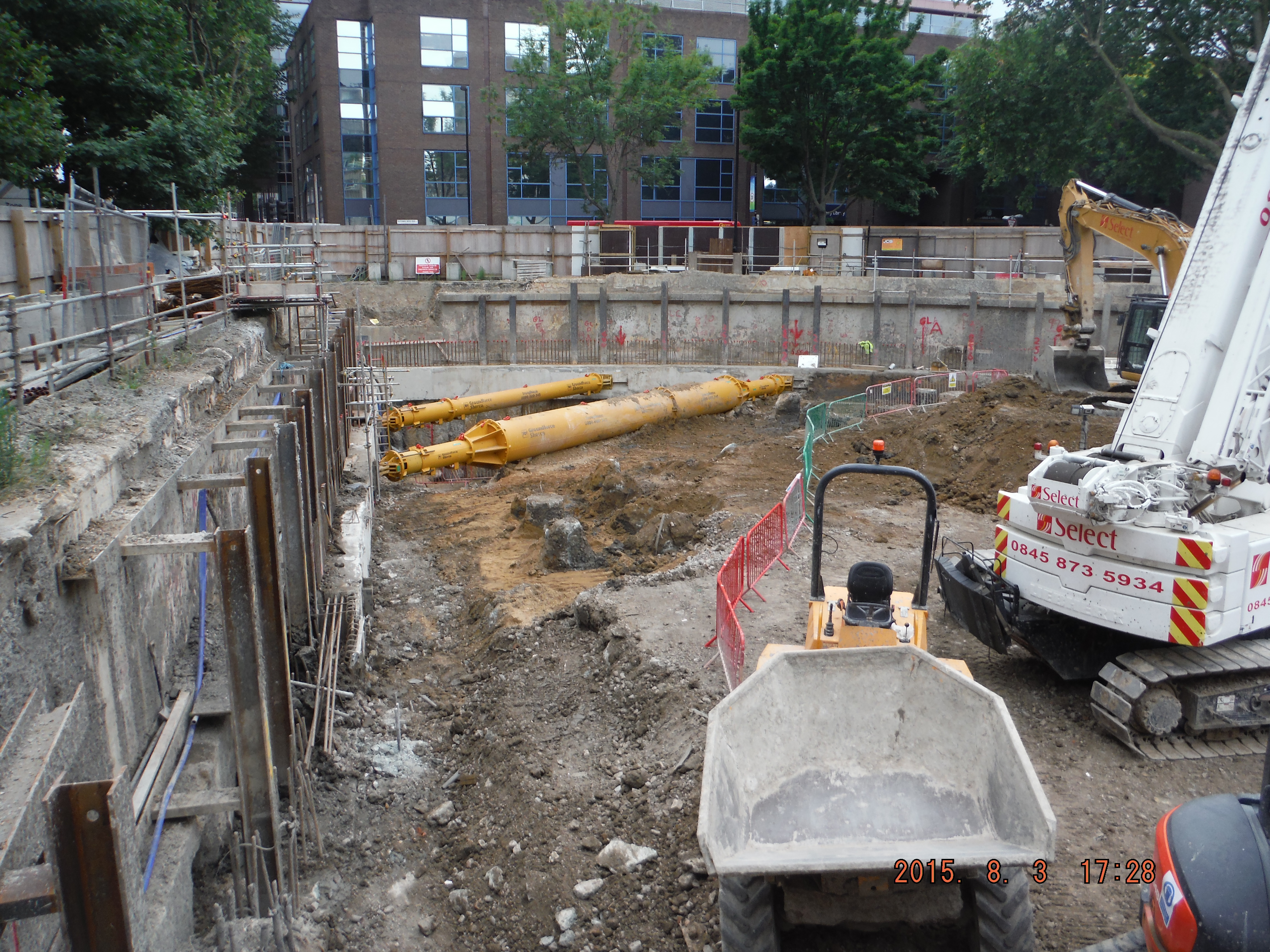
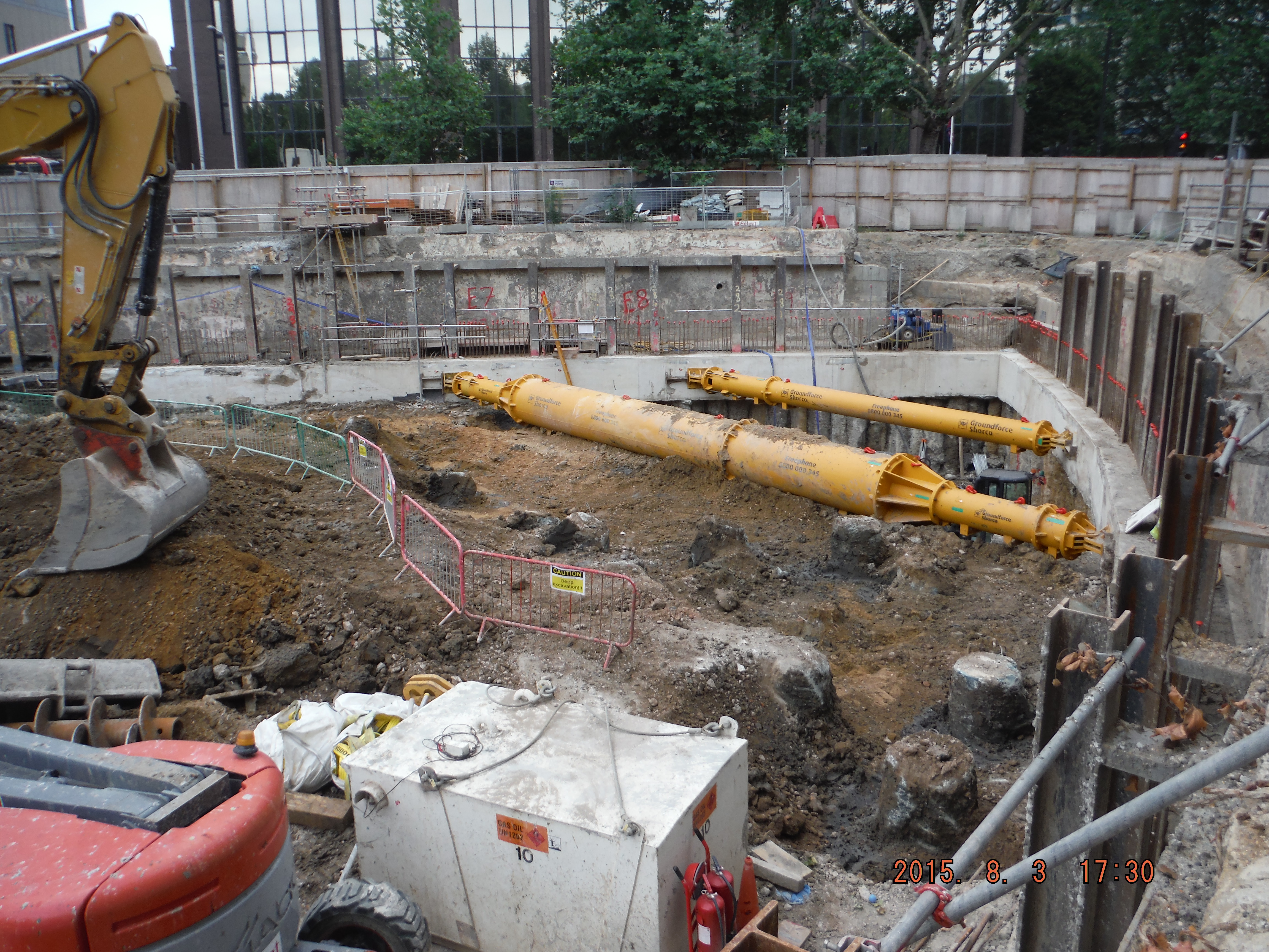
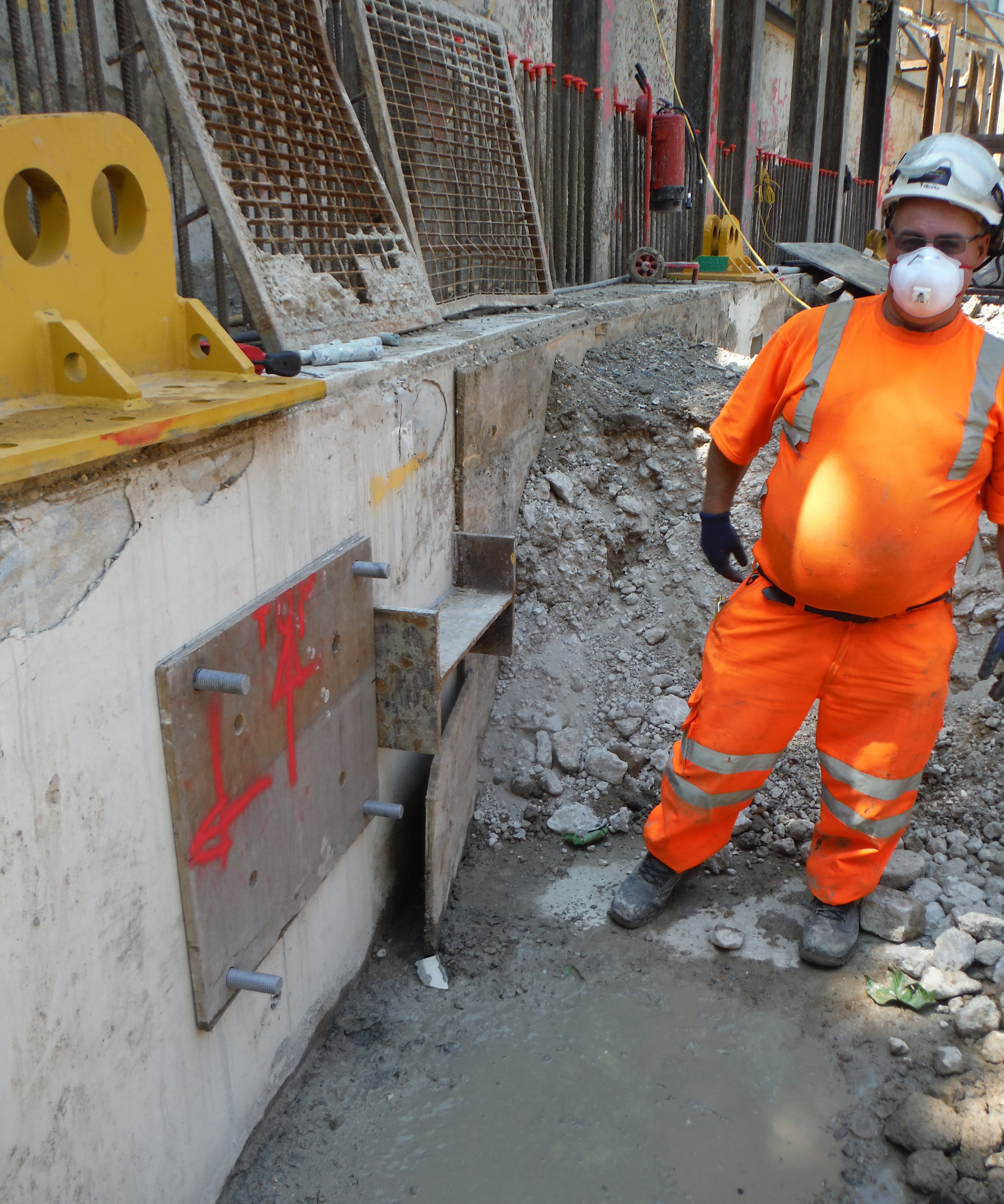
Props 1 and 2 in place
Excavation between bearing piles
Problem 3. Remaining props are likely to be installed prior to the capping beam reaching 50N/mm2. Similar situation to above, capping beam is designed for permanent loading, temporary design is for 30N/mm2. Looking at the cube results, this strength is reached between 15-25 days. Therefore, in theory, this is when the props can be loaded. To be more sure additional cubes will be cast and crushed to understand the rate of strength gain between 7 and 28 days a little better. Additionally the plan is to use thermocouples within the beam to understand the actual temperature of the concrete. This could then be replicated in the curing tank and rather than adhering to the 20 degrees standard, which should produce more realistic cube strengths similar to actual conditions.
Contract Update: Work on site is currently progressing at risk (no formal contract) – the monthly instructions to continue work ran until 20 Jul 15 and the next one (as far as 20 Aug 15) has not yet been signed off. The client has hand shaken on the main contract with Ray O’Rourke at £119M so clearly all will be fine!
Two Fifty One – Learning Simple Lessons (commercial x 2 and drainage clashes).
Two Fifty One – Learning Simple Lessons (commercial x 2 and drainage clashes).
Off hiring. As a way of reducing site clutter I arranged with the plant hire company (Select – an internal within Laing O’Rourke) to off-hire some RMD soldiers and Haki stairs.
Haki stairs for off-hire
20 RMD soldiers for off-hire
Simple and straightforward intent. Clearly getting rid of equipment would also mean the items are no longer paid for. So a few days later a 40ft low loader arrives from the plant hire company to collect the formwork. Utterly ridiculous size vehicle to remove the items which are small as shown above. A couple of weeks later and we receive a £300 collection bill! So in theory it would be cheaper to keep the items on site for months, than return them.
In short, the message is don’t forget about transportation/mobilisation costs of equipment. Albeit not a bank breaker, but a useful lesson early on.
Take off take offs.
Discussed on blogs recently was the subject of calling off drawings. I’ve called this “take off” here. Within the Two Fifty One project, my next focus is to plan the installation of the basement drainage. It is not a big job; the square area is about 1900m². However, having had the drainage runs priced from the drainage drawings by a Quantity Survey it makes sense to use their lengths and itemised totals as a check against the materials supplier totals. Lesson here is (I hope) that generally a lot of the length, area and volume calculations have already been completed for the project; therefore there is no need to repeat all of the work. However, caution must be applied to blindly assuming all is correct, designs have not changed, and it was priced correctly in the first place. Lesson – speak to the QS team (they aren’t just people who say no to all material orders!)
Drainage Clashes
The Two Fifty One development’s basement is founded upon 300 plus piles split between a raft pile cap for the tower and a series of smaller pile caps for the office. There are also two tower crane bases within the basement area.

General arrangement pile cap layout
The drainage design was produced on a standalone drawing with neatly drawn foul and surface water runs spanning between manholes.
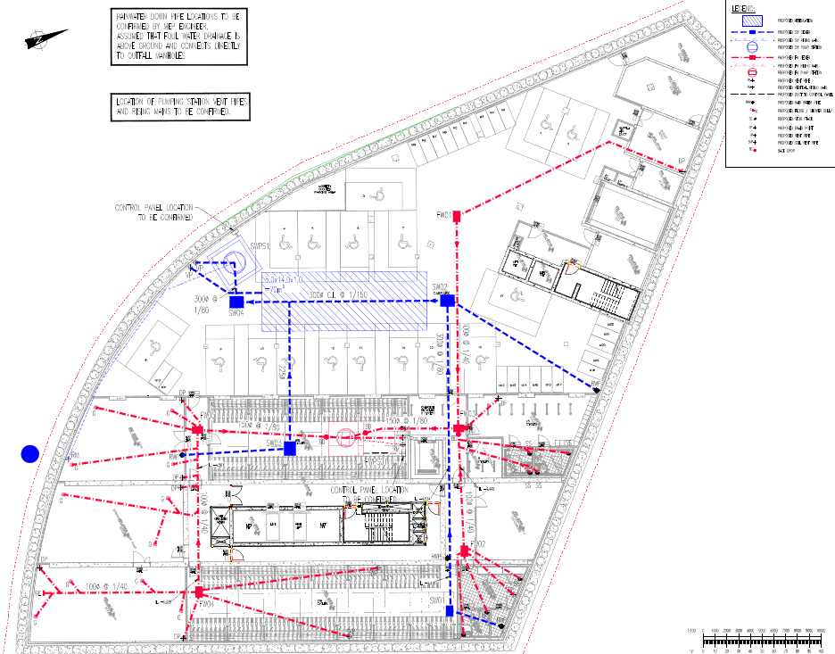
Drainage layout
Overlaying the 2 drawings (pile caps, tower crane footings and drainage) highlighted 6 pretty obvious clashes.
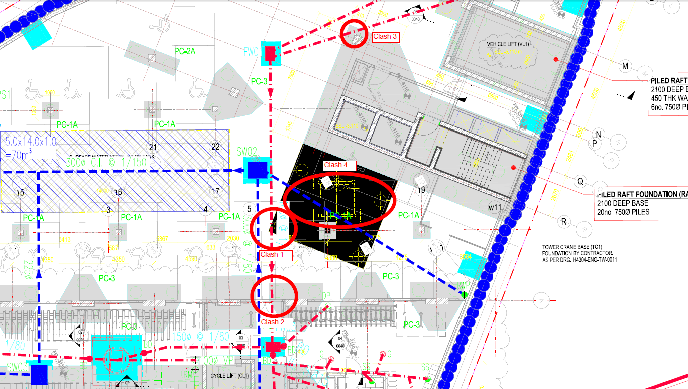
Clashes identified (1-4 shown).
3D images exemplify issue:

Clash 1 and 2 – Drainage run with corners of pile caps
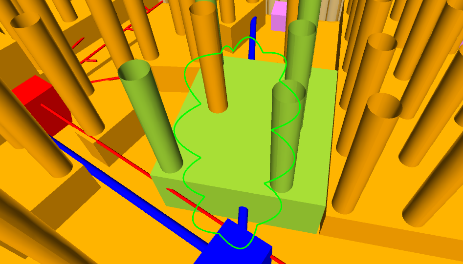
Clash 4 – Drainage run with tower crane base
I would think, as the designer was asked to do the overlay, they would have amended the layout. Nope and in fact the designer warned us (contractor) that these changes may delay the issue of the reinforcement drawings! So an RFI later, a much improved drainage layout was produced.

After: Clashes resolved (1-4, noting 4 sits better regarding position of tower crane base)
Without wishing to get into another pre-novation discussion, the time to resolve this issue is at the client’s cost (main contract still not signed so design risk currently sits with client). So I hope this will yield success in about a month when the drainage installation starts.
Site Two Fifty One – Dewatering while piling? and hot concrete.
Site Two Fifty One – Dewatering while piling?
“Draining the Bath”; this is our terminology for dewatering the site within the river terrace deposits now that the site is cut off from water recharge (secant pile wall bedding into London Clay). How soon is the question.
Considerations include plan area of site, depth of excavation, permeability, porosity and permissible discharge.
Various methods of how best to dewater have been discussed:
- Dig a hole to about 1m within the water table, insert a perforated pipe, insert sump pump within pipe and de-water. Repeat until required depth is reached.
- Drill out a core using the CFA auger and insert perforated pipe before the hole (wet gravels and sands) collapses.

View of site with pile rig roughly in the centre. When the excavation starts it will be from the far end of site and continue towards the near end (where photo is taken from). The second sump will be near the excavator bucket shown in the foreground.
I prefer option 1 because the sequenced lowering of the water table will reduce the risk of hole collapse because of not having to dig full depth in one go.
Some numbers. From the Ground Investigation the following figures have been assumed:
Initially dig depth: 5m, groundwater at surface of excavation, river terrace permeability: 1×10⁻³, porosity: 15%, plan area: 1900m2.
Putting this together gives 1500m3 of water which is to be removed using 2 sumps at either end of site.
The question is whether removing 1500m3 now, while piling is taking place is a good idea.

Image shows 2 sump locations. Sump 1 will be constructed by excavating down into the water, placing the pump and pumping until the ground water levels out. Repeat until 5m depth is reached.
Risk: Differential settlement. Removing 1500m3 of water is going to create (worst case) 15% more air voids which may settle up to 750mm. Clearly this assumes complete de-watering is achieved, when in reality there will be some moisture left within the pores. Additionally, the soil skeleton has strength and so despite the removal of water that does not directly imply the air voids will settle. If settlement does occur but happens evenly, then we could start dewatering now, but the risk is we don’t know.
Risk: Slip failure near to excavated area. Firstly the excavation edge will not be near to the piling operations. Secondly, by removing 5m depth of water will increase the effective stress by approximately 50kN/m2 – so dewatering will actually improve that risk.
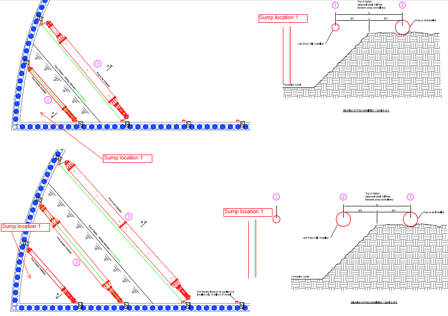
Method of excavation shown here in stages but sump 1 overlaid. Not risk of slip failure reduces as dewatering continues because of improved effective stress.
So what? Delaying dewatering until piling is complete will delay prop installation which delays excavation and the programme longer term.
Proposed solution to follow!
Hot weather and concrete.
Getting concrete in London is difficult at the best of times. However, this week a burst water main near Kennington has not helped, with delivery times exceeding 3-hours. With temperatures reaching into the forties, the concrete supplier has stated that tickets will have to be stamped meaning they cannot guarantee its quality! The concrete is for piles so the risk of quick curing is low once in the hole, the risk is getting it into the hole before it cures in the pipeline. This is not an issue I thought would be a problem in the UK, but turns out it is.

Burst pipe causes chaos.
The mix already has a plasticiser in it to make it workable for pumping and to enable cages to be plunged. To cope with the hot weather, the solution adopted was to add a retarder to delay the initial set. The retarder “slows down the initial reaction between cement and water by slowing down the growth of the hydration products”. The supplier, Lafarge Tarmac, does not have a plasticiser that works well in hot weather, hence the use of a retarder – it appeared to work well. The concrete did not cure in the pipes and the cages were plunged successfully.
Site Two Fifty One – Drainage and Confined spaces
Site Two Fifty One – Drainage and Confined spaces
Drainage
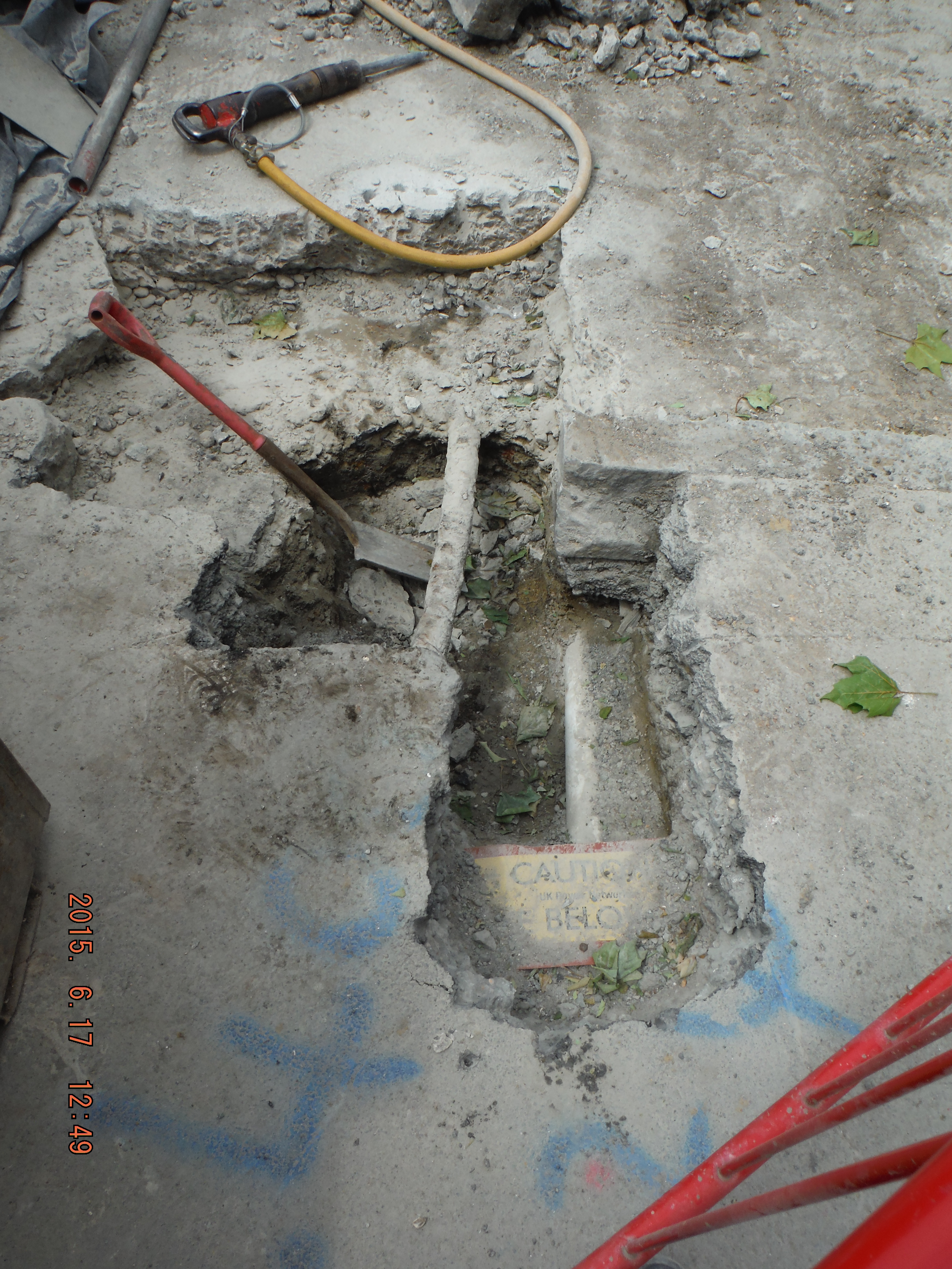
It was about time we had a drainage dilemma – my view is there will always be uncertainty when connecting to existing foul water sewers and unsurprisingly we have encountered a problem.
To put it mildly Manhole 02 has been a mess-up from the start. It is a new manhole with the purpose of connecting the site to an existing Thames Water pipe. Firstly the drainage drawing had it positioned in the wrong place. See the drainage drawing grid line B and structural drawing grid line B. Man Hole 02 is closer to grid line B in the drainage drawing than in the structural drawing.

Drainage Drawing showing location of new Manhole 02. Note proximity to grid line B.
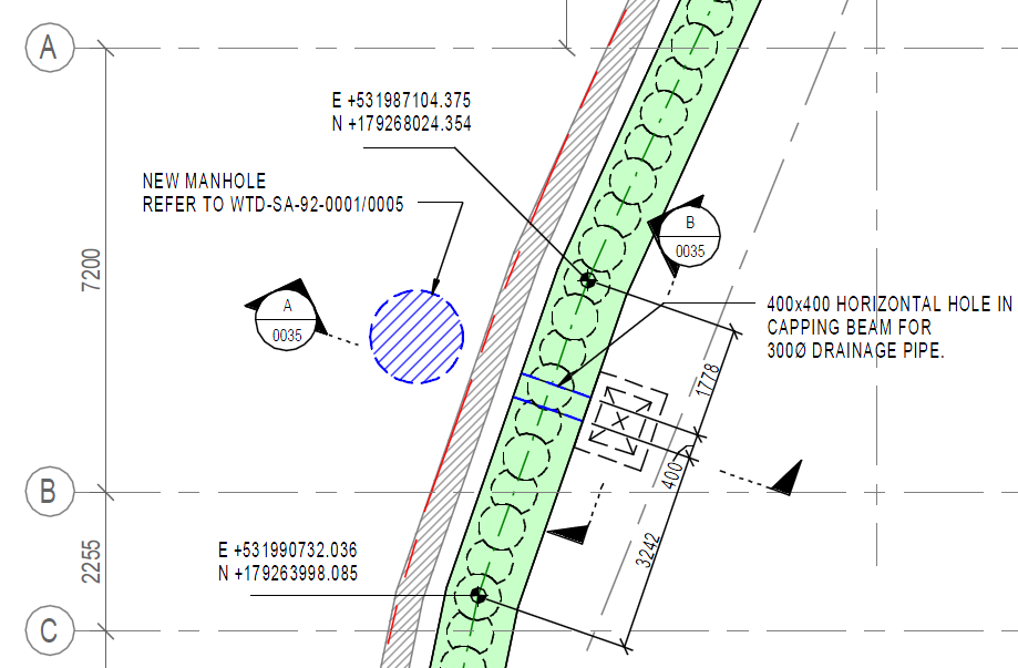
Structural Drawing showing location of Manhole 02 further away from grid line B.
So to fix the problem, as the issue was realised after constructing the manhole, a new header will be constructed – not hugely difficult, but it will cost someone something (more below).
Here is the real issue – Invert Levels.
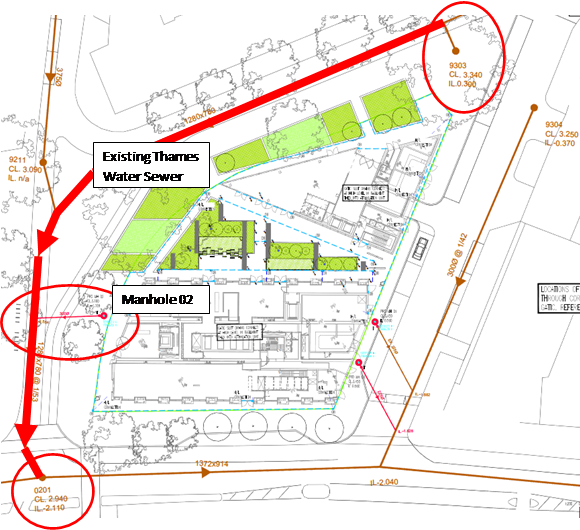
The drainage drawing of the existing Thames Water sewer invert levels looks to be correct. Invert levels taken at other existing manholes gives a pretty accurate picture. However when the heading from Manhole 02 was excavated towards the existing sewer no existing sewer was found. Mystery?
Earlier in the year a ground penetration radar survey had been done to identify existing services. At the time it showed that there were pipes under the ground so everyone was content. However, on further analysis of the study it appears the following was found:
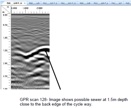
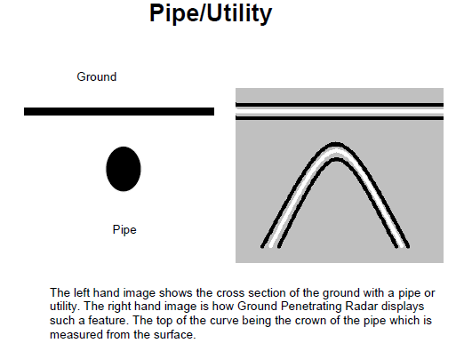
Print screens from the GPR report – pipe identified at 1.5m below ground level.
The GPR survey showed the following:
Ground level: 3.15m AOD
Pipe depth: 1.5m below ground level
Pipe diameter: 1.28m
Therefore invert level of the actual existing pipe: 0.37m AOD
The issue?
Going back to the drainage drawing the Invert Level of the Manhole 02 connection to the sewr is given as -1.109m AOD. Last time I checked water flowed downhill…
So why was the Invert Level designed at -1.109m AOD. Good old interpolation it seems. An upstream and downstream set of invert levels were used to interpolate between to give a connection invert level. Good idea, but as there is no pipe there it seems somewhere beyond the connection point the sewer drops down – i.e. runs at two gradients. (1 in 53 gradient now seems a bit steep).
So what?
For a start the issue is not resolved yet. There is little point burrowing around until we find the pipe. A drainage team are being employed to run a camera down the existing pipe to understand what it does. More onerous for the designers the difference in height of over 1m puts the inlet into the building higher within the basement level 1 floor – I am sure that can be overcome, but again someone will have to pay for that change. As we are still pre-contract, novation not yet occured, I suspect Laing O’Rourke will push the client to pay.
Health and Safety
This week we had a health and safety stand-down. This was not due to an incident on my site, but as a bit of a pre-emptive measure because there have been a number of reportable incidents on other Laing O’Rourke sites of late. We got the workforce look around their work areas and identify hazards and press home the importance of keeping walkways open and clear. A useful exercise, if nothing else to reinforce how important safety is on site and that starts with the basics of access.
You would almost have to try and obstruct a walkway as much as this!
Later in the week we had a Laing O’Rourke Safety Leader visit. The site was looking far better than it has done – segregated work areas, banksmen, coordination, signage and it generally appeared tidy. However, we have a sub-contractor, Murphy, undertaking works to install further manholes (and to fix the debacle around Manhole 02 I have mentioned above).
Manhole 02 temporarily paused while the connecting (existing) sewer is found.
The start of Manhole 03 – plenty of existing services to deal with.
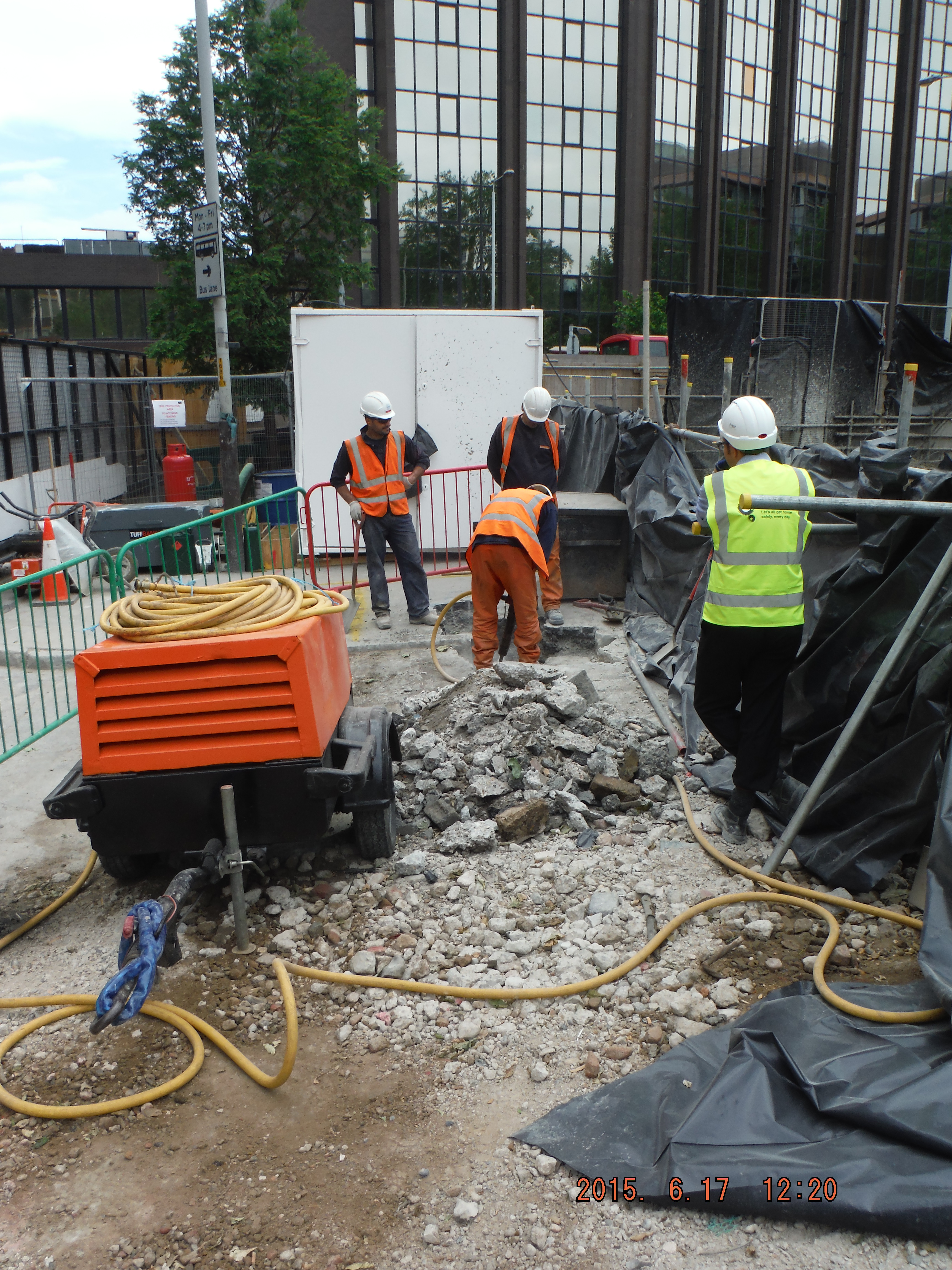
Manhole 03 – confined space approaching as the hole is deepened. Compressor fumes settling into the hole (confined space) present a significant hazard.
The question was asked, from the Main Contractor (Expanded Structures in this instance, filling the One Team role of working for Laing O’Rourke), who is confined spaces trained? The second question was, what is a key hazard of working in confined spaces? Not my answer, but one I might have given is: structural integrity of the hole being dug. No – fumes from both the compressor an excavator filling the hole so when the operative enters he gets into difficulty. Clearly the Murphy operatives need to be trained in confined spaces, but so does the main contractor.
So What?
“Under domestic law (the Health and Safety at Work etc Act 1974) employers are responsible for ensuring the safety of their employees and others. This responsibility is reinforced by regulations.”
The Confined Spaces Regulations 1997 contain the following key duties:
avoid entry to confined spaces, eg by doing the work from outside; (not possible)
if entry to a confined space is unavoidable, follow a safe system of work; (yes in place) and
put in place adequate emergency arrangements before the work starts. (yes in place)
Even though safe systems of work have been checked, because there is deemed to be a lack of competence (no training) of the main contractor to supervise the works, this must be rectified and an appropriately competent person will need to review the method statements and emergency procedures.
Reflecting on this – it now seems pretty obvious that to adequately approve a sub-contractor’s safe system of work, the main contractor must be trained (in this case in confined spaces). The question is what is competent. If it is where all practicable measures have been taken to reduce risks, then we fail – experience without training is perhaps another way of saying it worked last time so it’ll be alright this time – i.e. a dangerous place in be and we are not even in the hole yet!
Finally a couple of concrete finish photos: F5 (flow not slump), C40/50, Waterproof concrete…
Decent finish, shame about tie bar holes.
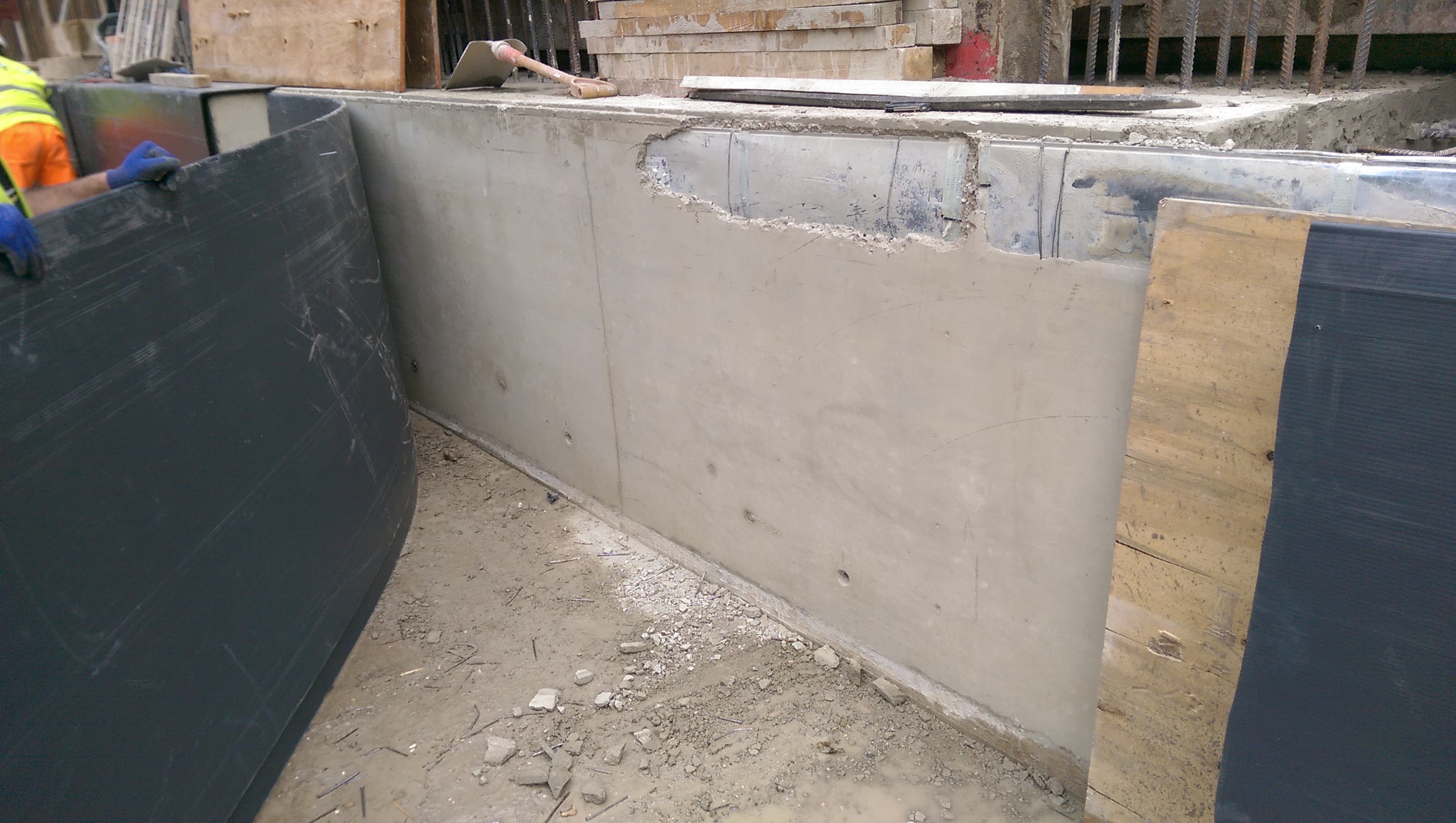
Cordek plastic sheet being used to protect the face of the capping beam. Kwika strip being revealed at the top of the beam.
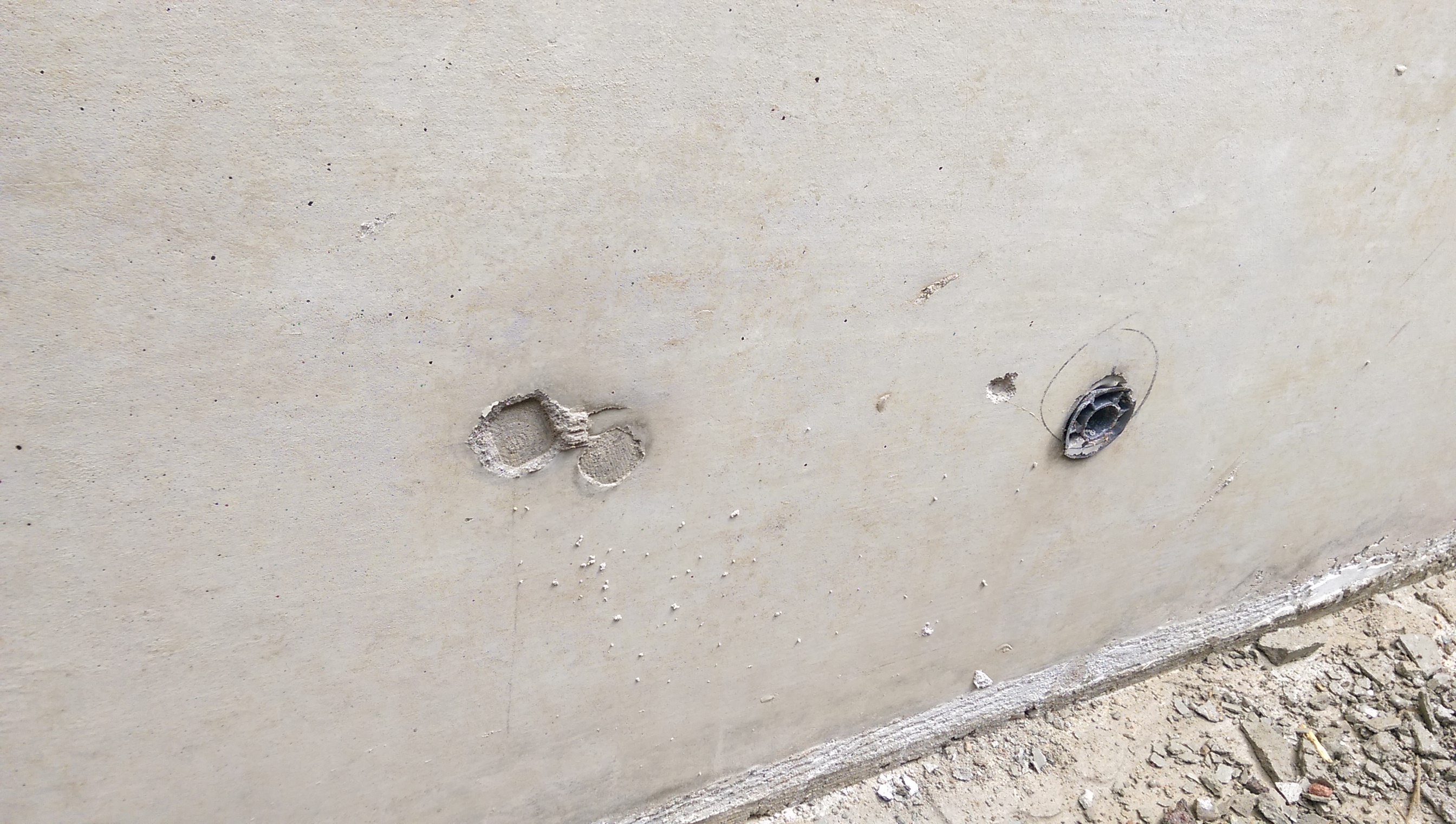
Shear stub for props – note fibre board used to create a recess around it to allow the stub to be burnt off and made good many months down the line.

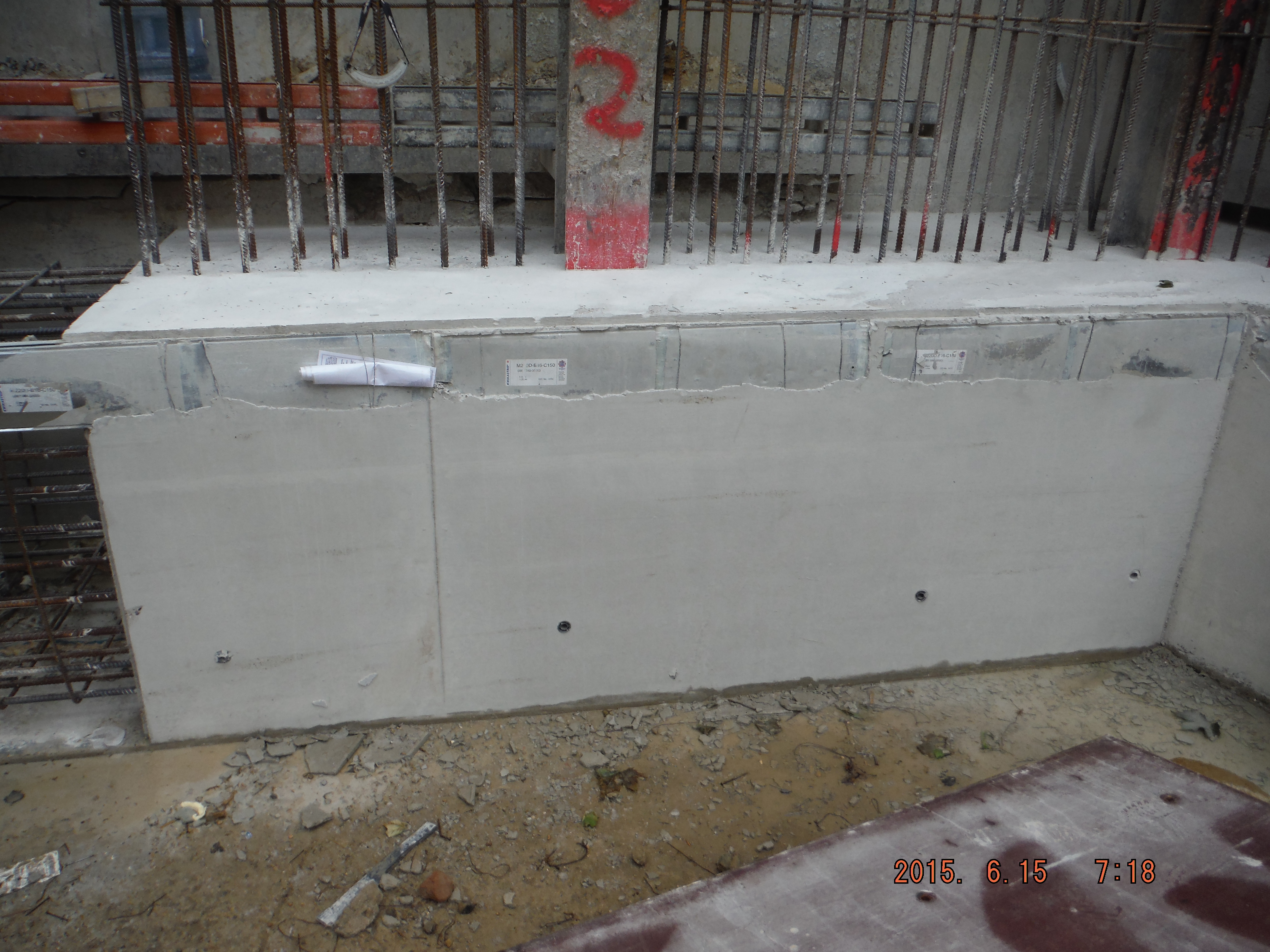
More of the same – note blinding layer at base of capping beam to be removed during excavation of ground.
Site Two Fifty One – Concrete strength and Waterproofing
Site Two Fifty One – Concrete strength and Waterproofing
A set of cubes for each capping beam pour is taken. BS EN 206 states that any individual 28 day result should be no less than characteristic strength- 4N/mm² and a rolling set of 3 should have a mean less than characteristic strength+ 4N/mm². This means 46N/mm² or 54N/mm². Recent results put it near to the 54 N/mm² limit.
However, after some discussion, the aim now is to use the 56 day results to confirm compliance.
The capping beam cube results have also come back with the piling concrete results. Their mix uses a 50:50 proportion of Portland cement to Ground Granulated Blastfurnace Slag which brings a faster strength gain up to 28 days compared to my mix of a higher (70%) GGBS quantity.
Between 28 days and 56 days there should be more strength gain of the higher GGBS proportion concrete. Although the 56 day strength of the 70% GGBS will be lower overall, there is more gain of strength later on, than that of the Portland cement: GGBS 50:50 mix.
More eloquently:
“Typically a CEM I concrete will achieve about 75% of its 28-day strength at seven days, with a small increase of 5–10% between 28 and 90 days.
At 70% GGBS, the seven-day strength would be typically around 40–50% of the 28-day strength, with a continued strength gain of 15–30% from 28 to 90 days.”
Reference: Cementitious Materials – The effect of GGBS, fly ash, silica fume and limestone fines on the properties of concrete.
So what and who cares?
Faster strength gains (found with higher Portland cement content) = higher heat of hydration = more likelihood of cracking in deeper members. Therefore reducing cement to GGBS content, as long as the eventual strength is of that required (50N/mm² in my case), helps reduce cracking. Who cares? – People who construct below the watertable – me and my project!
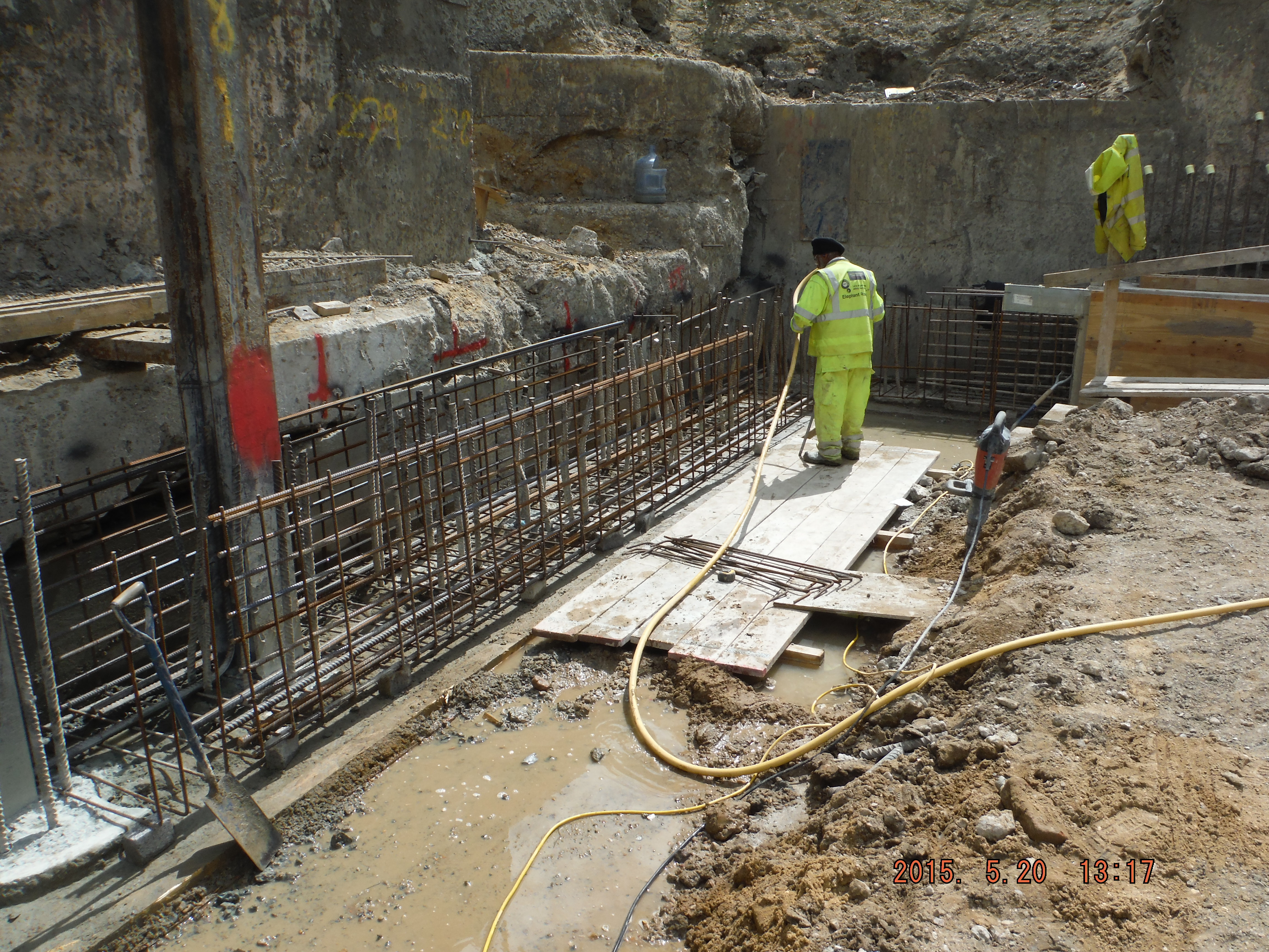
Waterproofing
Reflecting on Guz’s comments on the cost of injection grouting cracks to improve the waterproofness of concrete, I am at the pre-pour stage.
We are using a hydrophilic (absorbs water over time) material to form a watertight joint between the top of the piles and the base of the capping beam.
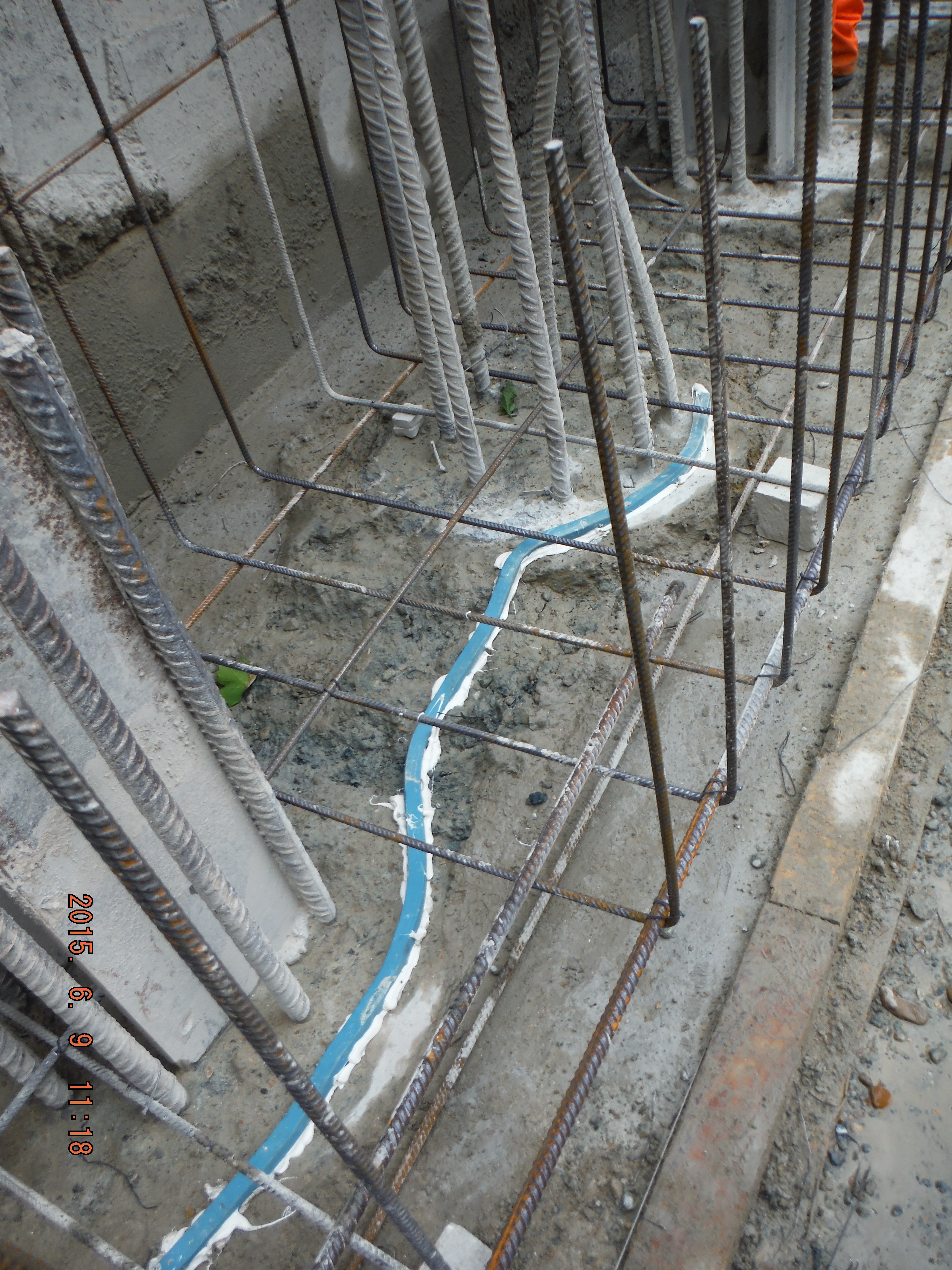
Hydrophilic strip laid along length of secant piles within “waterproof” section.
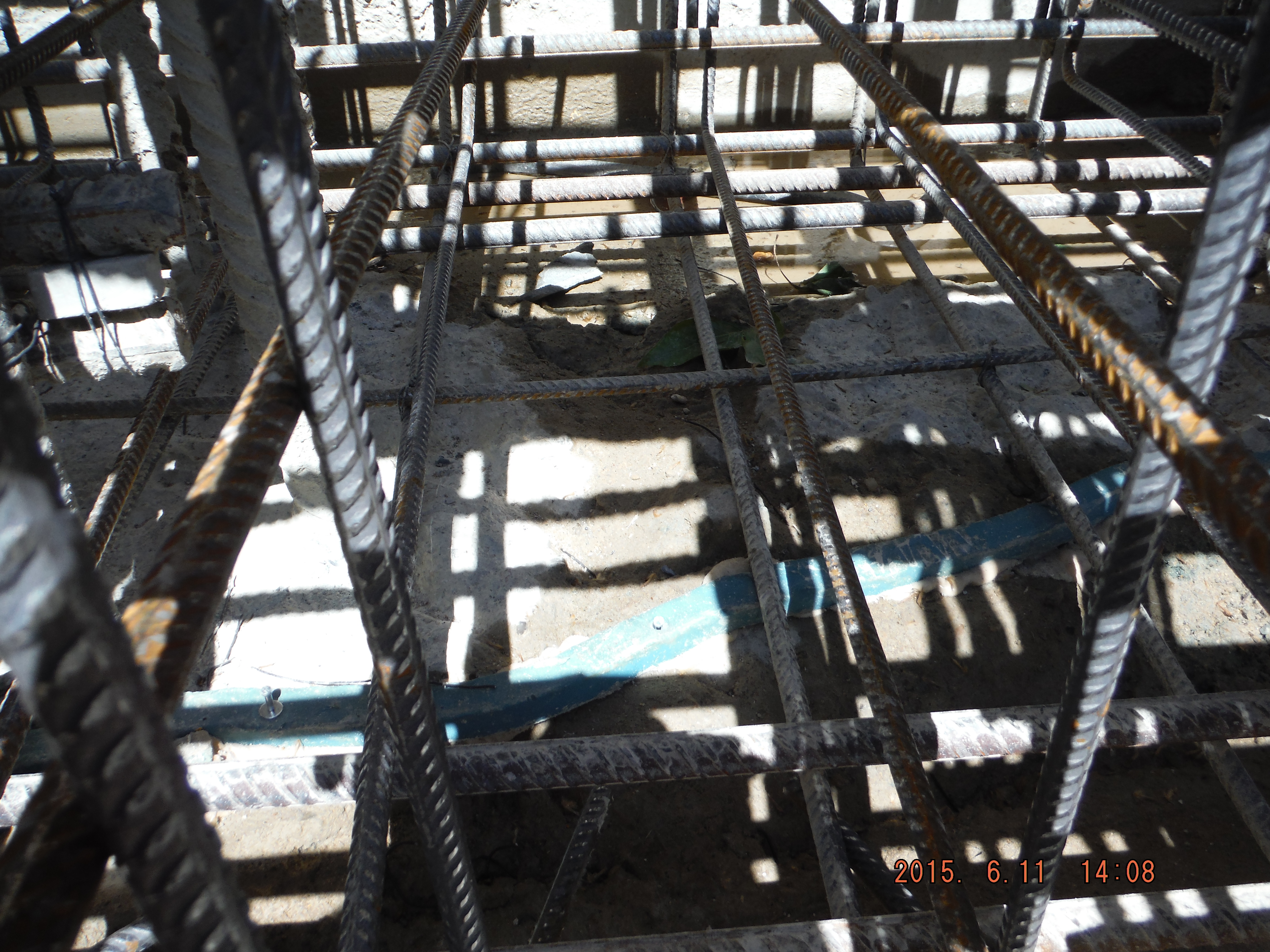
Line of hydrophilic strip.
Hydrophilic strip fastened around king posts.
Thoughts.
The advantage of this system is that the joint between the surface of the piles and the bottom of the capping beam will not provide a path for water to pass along.
However, there are fairly significant reality issues with this.
- The piles have been broken to cut off level using breakers – therefore the surface is overly rough and uneven (beyond the mechanical interlock required for a structural joint).
- In the instance of an uneven surface a mastic beading is to be used to sit the hydrophilic strip onto. This is then supposed to be nailed to the piles. Issues here are using masonry nails has safety issues – they fly out and hit people, the nails also provide a water path.
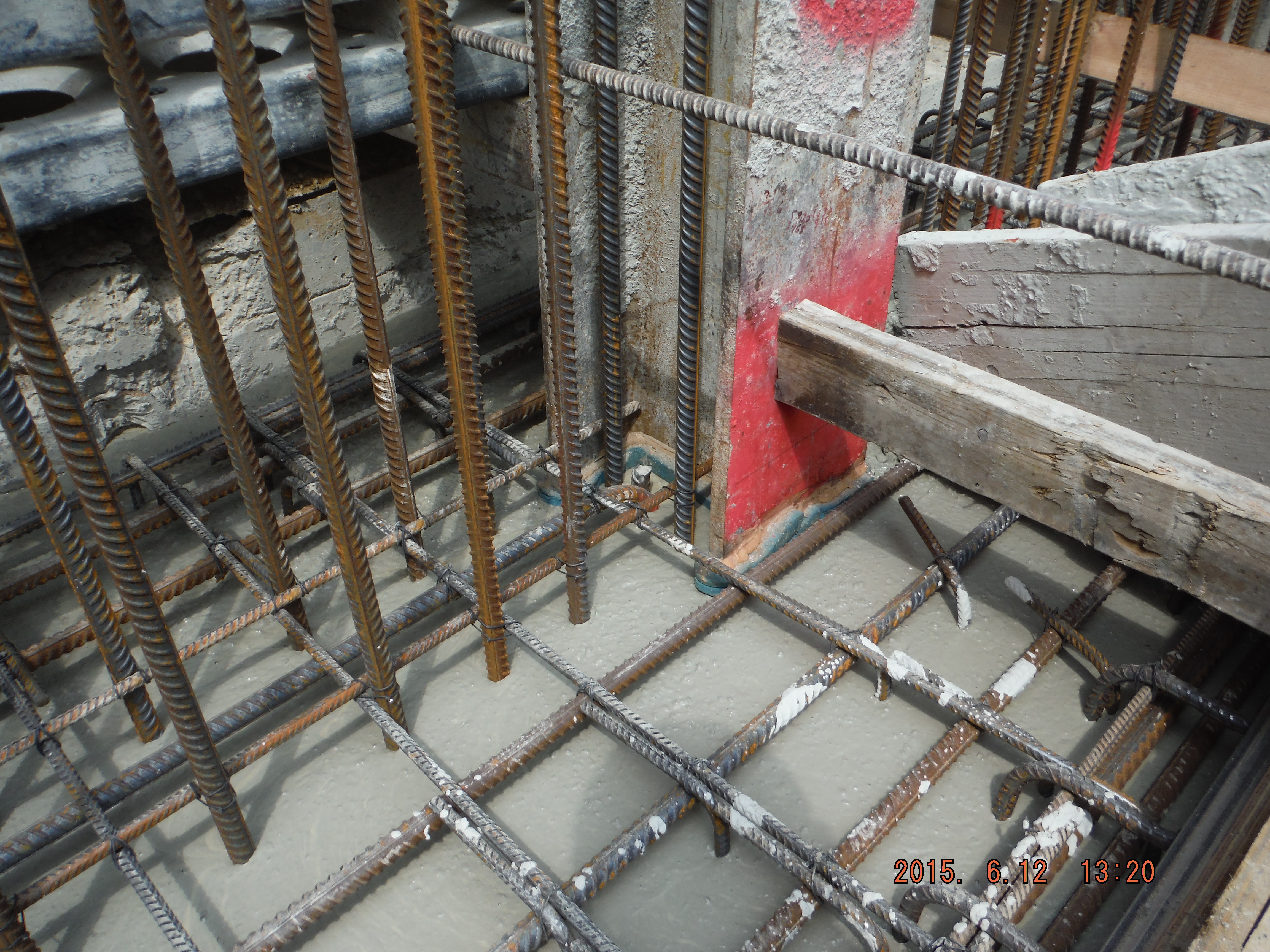
- The reinforcement cage needs to be installed after the hydrophilic strip has been laid. Therefore during the installation of the cage great care has to be taken to avoid standing on the strip.
Waterproof concrete
Finally, and I will only touch on this, we are using waterproof concrete to ensure water does not pass through the capping beam in certain areas. The Grace (company supplying waterproof admixture) datasheet provides a comparison of permeability of the control concrete compared to the waterproof concrete as follows:
Control: 6.90 x 10⁻¹⁴ ms–1
Waterproof: 1.28 x 10⁻¹⁴ ms–1
This translates that in 10,000 years the waterproof concrete might have water penetration of 4mm compared to control concrete of 21mm. Last time I checked, design life of buildings was somewhat less. When identifying risks – this (concrete permeability) is not one of them.
Conclusion
More important are the joint preparation, crack control – through mix design and curing methods and vibration to reduce porosity.

Capping Beam concrete pour with waterproof concrete.
Site Two Fifty One – Commercial Aspects
Site Two Fifty One – Commercial Aspects
I will turn attentions to some commercial aspects this week.
Firstly, warranty and building insurance. There were two inspections of the capping beam recently. One from Assent Building Control and one from AECOM. The purpose of each was slightly different.
Assent Building Control inspections are to confirm that the building is being built in compliance with Building Regulations, i.e. planning requirements. The inspection was of reinforcement for the capping beam. The inspection included a general look over the area and to make sure the cover to steel was correct. There did not seem to be much reference to the Building Regulations – Approved Document A (Structure), Parts A 1&2: Loading and Ground Movement, or Part 3: Disproportionate Collapse. Now clearly the project is at an early phase, and the inspection was of a ground beam, but I would have expected slightly more inquisitive questioning. It felt like it was as much a waste of the inspector’s time as it was mine!
The client has also engaged Allianz Insurance to provide a 10 warranty on the building. Allianz have then engaged AECOM to provide external, independent quality assurance that the structure is being built in accordance with the design. The inspector had extracted relevant drawings from ASite (file sharing website) and was keen to see the section of capping beam that the 40 storey building is going to sit on. The 9 x H32 top and bottom bars, acting in bending, were checked and he was happy. The mass of other steel (for temporary props) was not his concern because he will provide the insurance for 10 years after completion of the structure, not if it falls down in construction.
Capping beam reinforcement cage construction
So what?
It is good that AECOM chose to visit an important part of the structure and that the key part of the steel was checked (and that the inspector had printed drawings and knew what he was coming to look at). I think this shows more of an appreciation of risks involved than just a generic check as per the Building Control one.
Second part – Contract or not to be…
The project I am working on started with an enabling works 26-week contract which covered a secant pile wall, tower and office bearing piles and the pile capping beam. We are now in about week 30 and there is still no full contract. Laing O’Rourke had previously quoted a price in January 2014 which was 10 million lower than the contract price submitted a few weeks ago.
This has prompted an intensive period of value engineering to see where savings can be found. The in-situ basement box and precast frame were re-costed reaching a similar total but the mechanical and electrical and fit costs out have increased.
So what?
The building price has increased by about 10%. The value engineering meetings have found savings but also additional costs.
The client is also pushing hard for sequential/early occupation. Great to get people into their flats early, but at the same time this creates havoc with commissioning – I understand it is difficult to only commission half of a fire alarm system and equally expensive to commission a lift shaft more than once. Therefore the benefit of improved cash flow gained through early occupation is lost in additional commissioning costs.
So so what?
Not having a full contract and running on a rolling monthly extension to the enabling works contract makes organising the project difficult:
Precast – Laing O’Rourke are the pioneers of precast: columns, walls, beams and slabs (Design for Manufacture and Assembly). Great idea, but if the lead time is 22 weeks for production, a rolling contract is not the way to get things done.
Designs – Without a contract, the detailed design is being completed ‘at risk’ and each component part (sub-contractor) of the project is a little wary of committing time without the assurance of a contract as to whether the building is going to go ahead.
Today we had an unannounced visit from Des O’Rourke – co-owner of Laing O’Rourke. Not a common occurrence, so with a visit yesterday of another senior director, I suspect it is coming to crunch point on whether the project gets the green light beyond the enabling works! It is an interesting time in construction in London – there is no shortage of work for contractors and so I think if a client wants something, they are going to have to pay for it. Gone are the days of simply agreeing on projects to retain cash flow (at least at the moment).
I’ve been a bit light on photos, so here are a couple of other ones:
Guide wall construction using polystyrene formers:

Post pour “half-moon” interlocking secant wall