Archive
Site Two Fifty One – Environmental Awareness
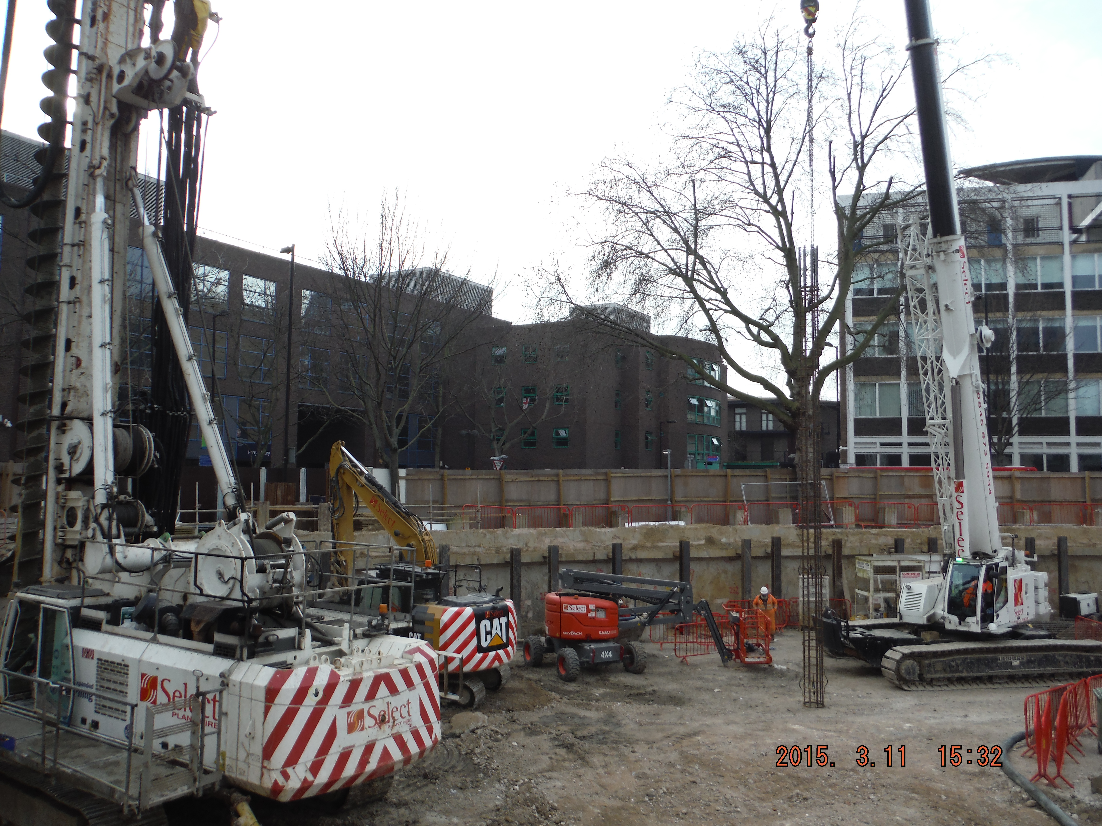
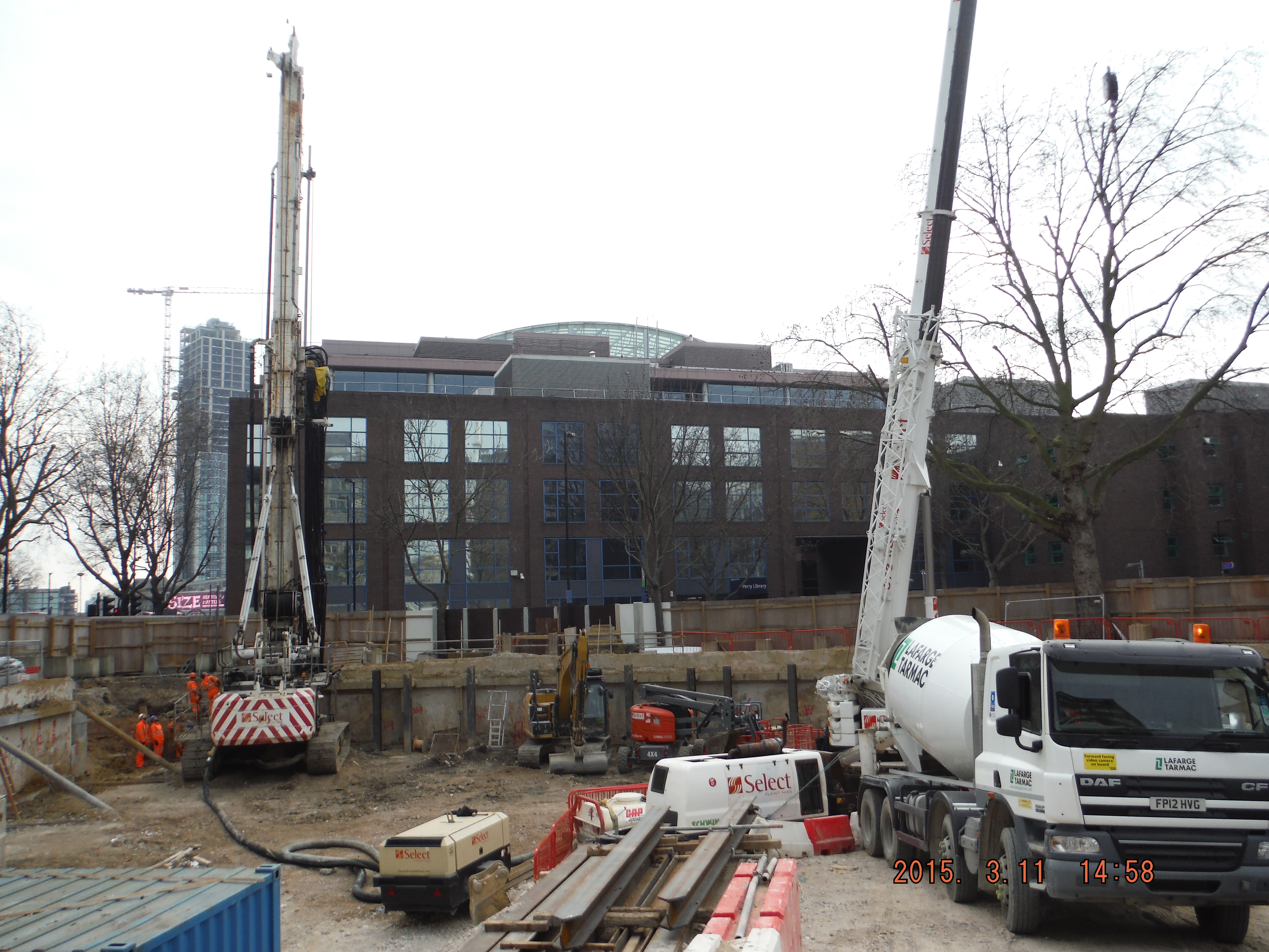
As site Two Fifty One continues to get established part of the works have included moving the hoarding outwards. This gives more space inside and sets the correct position for the entrance gates. However, outside of the original hoarding line were 6 mature trees (trunk greater than 100mm/greater than 10 years old). They now sit within the site.
Left – See concrete blocks with posts on – this is the original hoarding line. Right of tree – see blocks moved to edge of pavement, tree will now sit “inside” the site.

Tree within hoarding creates ecological value, therefore making it harder to gain credits for improving the site’s ecological value in the future.
So What?
The original site survey in 2007 determined that no trees sat within the site, therefore it was classed as having a ‘low ecological value’. This presents two advantages: 1. No effort required in protecting trees or other species and 2. Using the Building Research Establishment Environmental Assessment Method (BREEAM – See areas below) and Code for Sustainable Homes it is easy to gain credits by planting trees in the future to turn the site into a development with ecological value.
- LE 02 – Ecological value of site and protection of ecological features – Two Fifty One is starting at a low baseline (i.e. no trees within the site).
- LE 04 – Enhancing Site Ecology (easier if LE 02 is met because low start point)
- LE 05 – Long Term impact upon Biodiversity (add more trees!)
This reminds me of John’s brief of Rich Phillips’ TMR discussing BREEAM based credits gained for little extra effort (points for being near a bus stop – quite likely in a high population urban development!). The aim is to avoid the loss of credits, which in all tally to give a ‘very good’ rating, would mean the project would slip down a notch and therefore not comply with planning consent. Seeing as the client is still to approve Laing O’Rourke’s tender for the superstructure, now failing to meet the planning requirements would be pretty embarrassing.
So how is this problem going to be resolved. Along one side of site it is simple; sections of hoarding will be moved to inside of the 5 trees. Unfortunately, one tree in a different part of site cannot be easily excluded from the site. BS 5837:2012 (Trees in relation to design, demolition and construction – Recommendations) states: “It might be feasible on some sites to use temporary site office buildings as components of the tree protection barriers, provided these can be installed and removed without damaging the retained trees or their rooting environment”. This is particularly handy because the site store is going to be positioned next to this tree and will actually act as a useful barrier to prevent damage to the tree. This means the tree is protected
Is it right that credits are given for a tree to be outside or inside a hoarding line? The advantage is, if it is outside, the trunk will not be knocked and bashed by construction traffic or have materials stacked against it. It also means that the development is likely to have a focus on green areas and planting vegetation – which is a good thing.
So in all, is BREEAM and the Code for Sustainable Homes actually going to help the ecology of the local area? Somewhat. By signing up to the “Very Good” BREEAM rating the project is accountable for carrying out its actions as it said it would to the local council. Therefore simply removing trees cannot happen and even small things like protecting trees will be taken seriously.
Site Two Fifty One – Some Engineering Thoughts
Tower cranes. If a tower crane were to fall over and land within 4m of a railway, it must have its foundations checked 3 times (initial design, internal check and external check).
As part of the risk mitigation requirements Network Rail say the crane has to have its working load reduced to 75% of its capacity. Generically this seems sensible – reduce the load to reduce the possibility of the crane falling over.
Due to the location of the railway in relation to the tower crane, it is clear the adjacent buildings prevent the crane from slewing onto the track when loaded. Therefore any variable load would act in a restoring fashion, reducing the possibility of the crane overturning towards the railway.
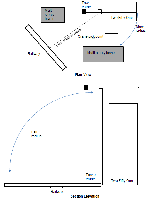
Sketch showing tower crane position in relation to other structures.
Therefore reducing the working load would in fact make the situation worse. The worst load case is therefore an unloaded crane with wind loading. So I’m not so sure a generic application of reduction in loads by 75% makes sense…
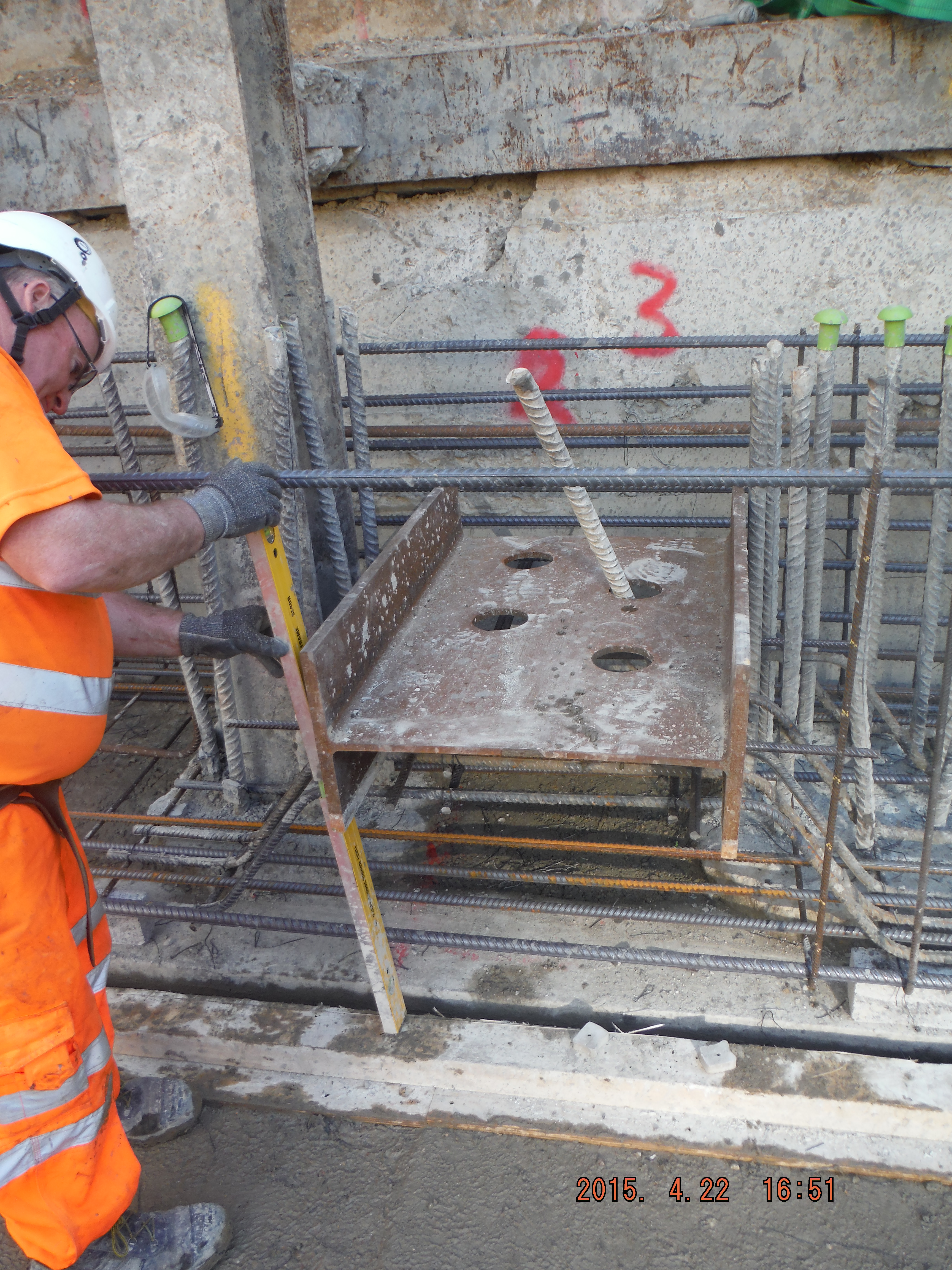
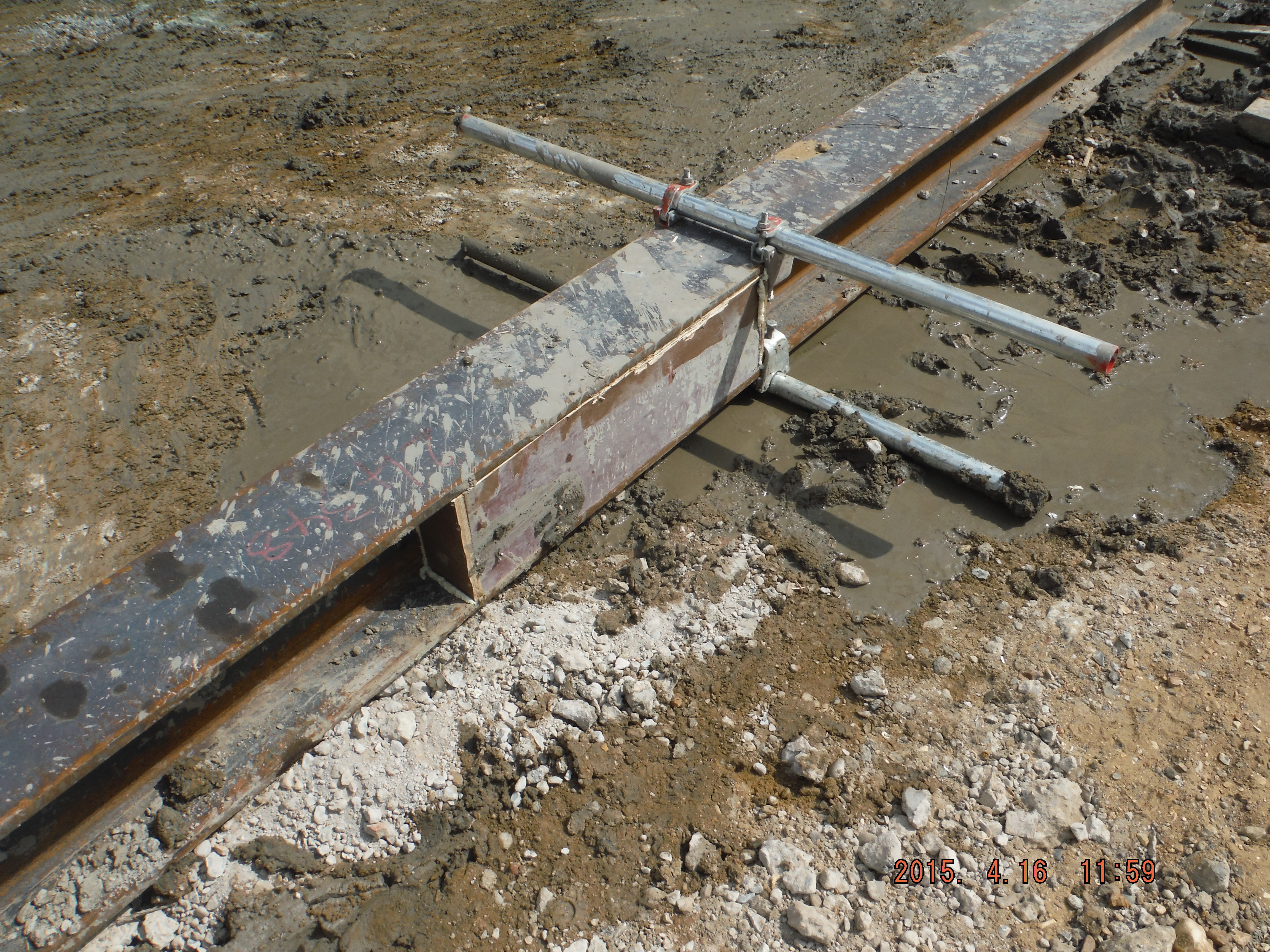
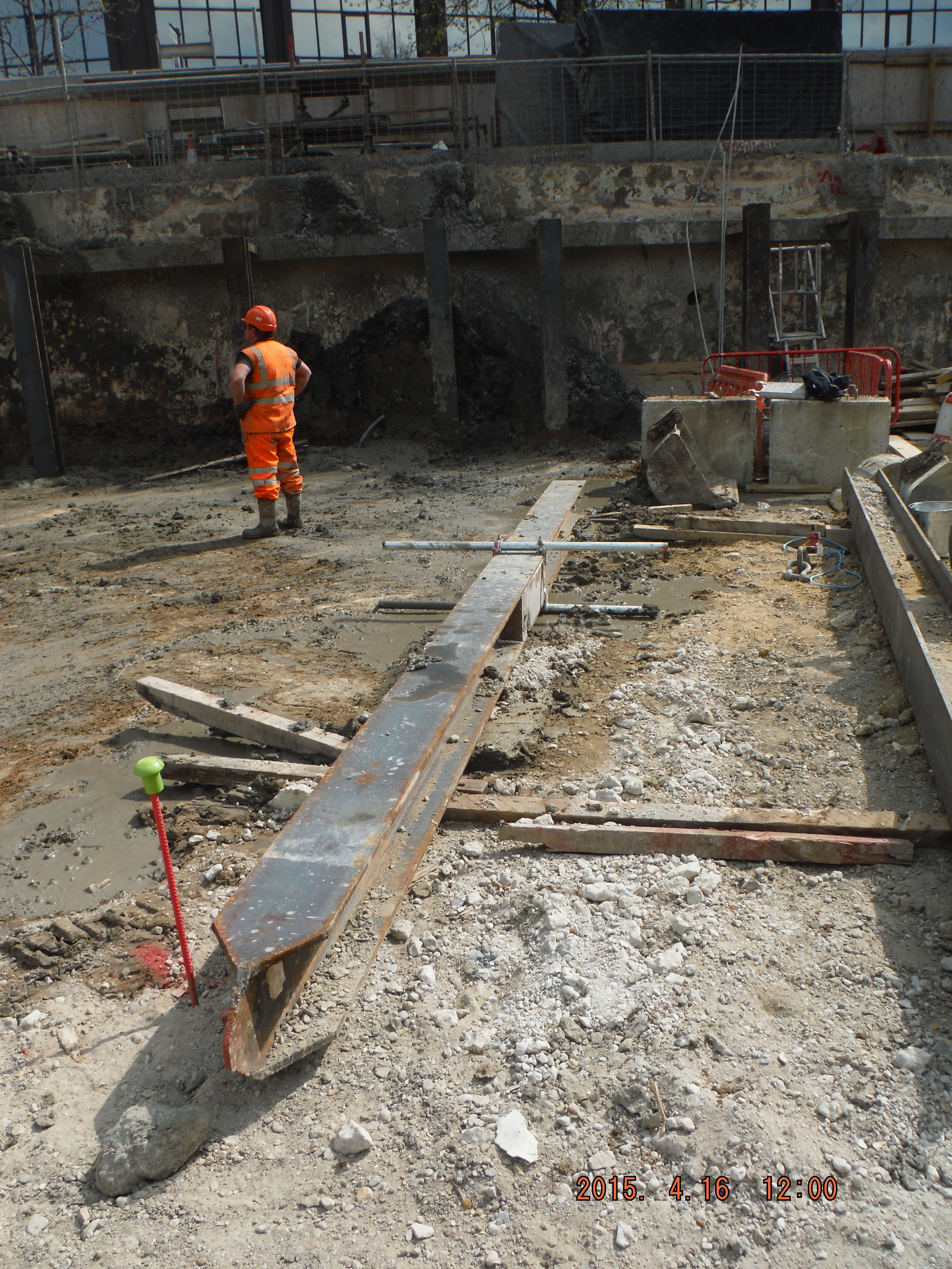
Shear Stubs. I beams laid on their side have been used as “shear stubs” to resist shear force applied from the retaining props fixed across the site. The stubs have to have reinforcement bars protruding through them. The holes for the bars were put in the wrong place.
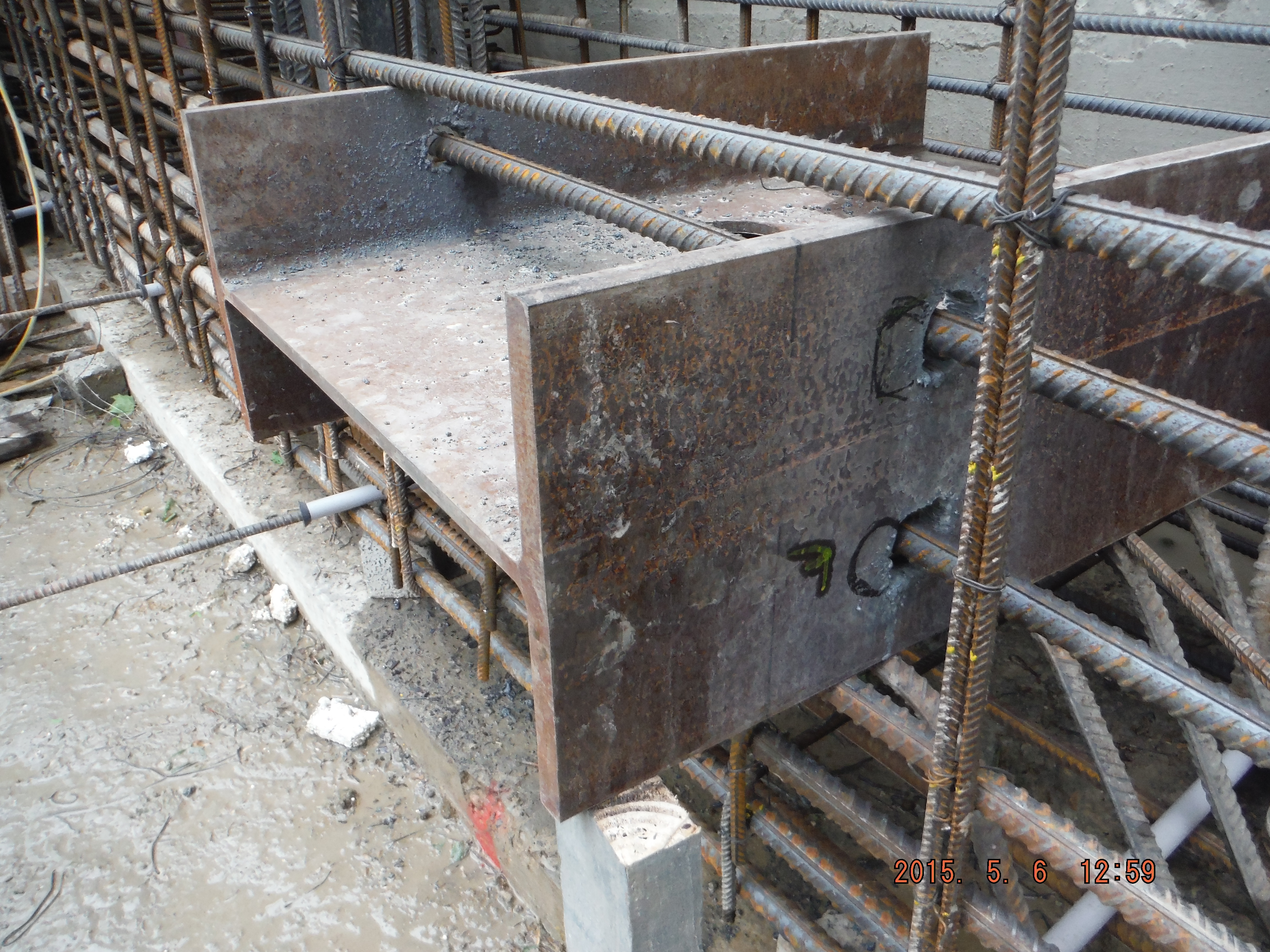
Shear stub, reinforcement holes in the wrong place.
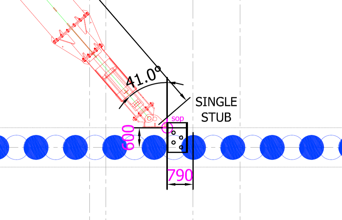
Example of a position of shear stub in relation to prop.
So what? Correcting the problem (increasing the hole size) will result in the flange having a reduced area to be able to resist the force applied.
Action taken? Remove shear stub and have a think.
Thoughts:
- Different stubs have different shear forces applied depending on angle (angle near 90 degrees = less force applied against stub) of the prop (and axial prop load).
- A stub is designed to take a point load of up to 1200kN. The highest prop load is 1140kN giving a 95% utilisation.
- The stub is encased in concrete and therefore it provides resistance against its flange area (625mm x 307mm = 192,000mm squared).
- The area is reduced by 2 x 50mm diameter holes for rebar to pass through (4,000mm squared).
- The incorrect holes reduce the bearing area further by 9000mm squared.
- Based on a total area of 188,000 mm squared the reduction in area is less than the 5% capacity of the worst case situation.
- So the answer – Keep the stub in (too late), reuse stub in any location.
Other thoughts. If the holes were drilled too far towards the near face (i.e. where the prop end plate will act), consideration of the section failure in bending would be important as the section modulus would be reduced, and therefore moment capacity in bending.
Site Two Fifty One – Concrete
Site Two Fifty One – Concrete
This week the concrete pour for the first section of capping beam was completed. After the discussions on my last blog, the pour size was reduced to 16.6m (from 40m).
Formwork. The shuttering worked which was pleasing because we had brought the pour forward a day due to a lack of concrete availability on a Friday before a long weekend and so it was somewhat manic to get things ready in time. It did mean the grout check line was being installed while the concreting started!
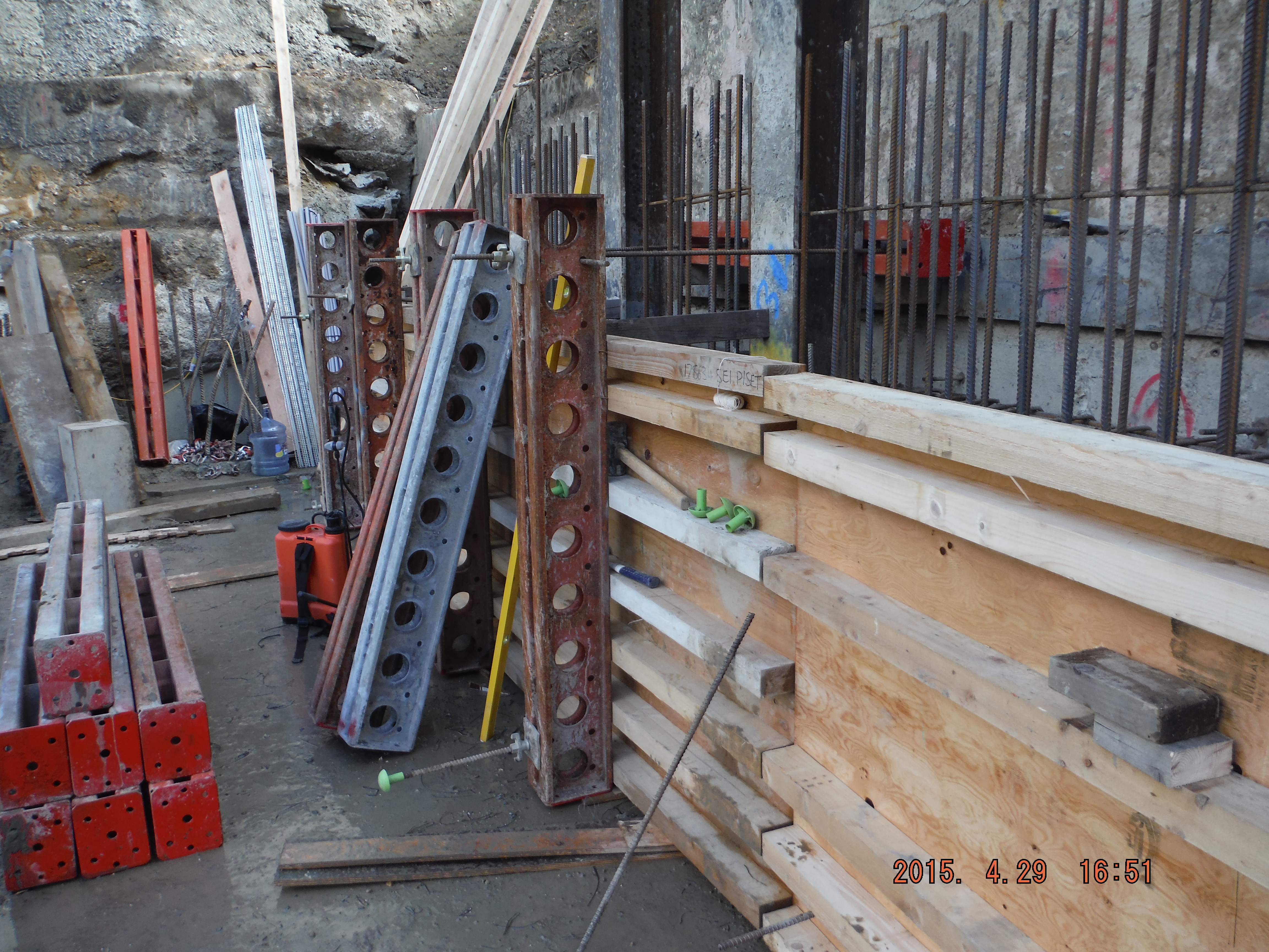
Formwork construction. Waler beams only 100mm deep, therefore smaller spacing at bottom to remain within moment capacity of the section. Soldiers at 1.2m spacing to align with male pile reinforcement which the dywidag ties from.
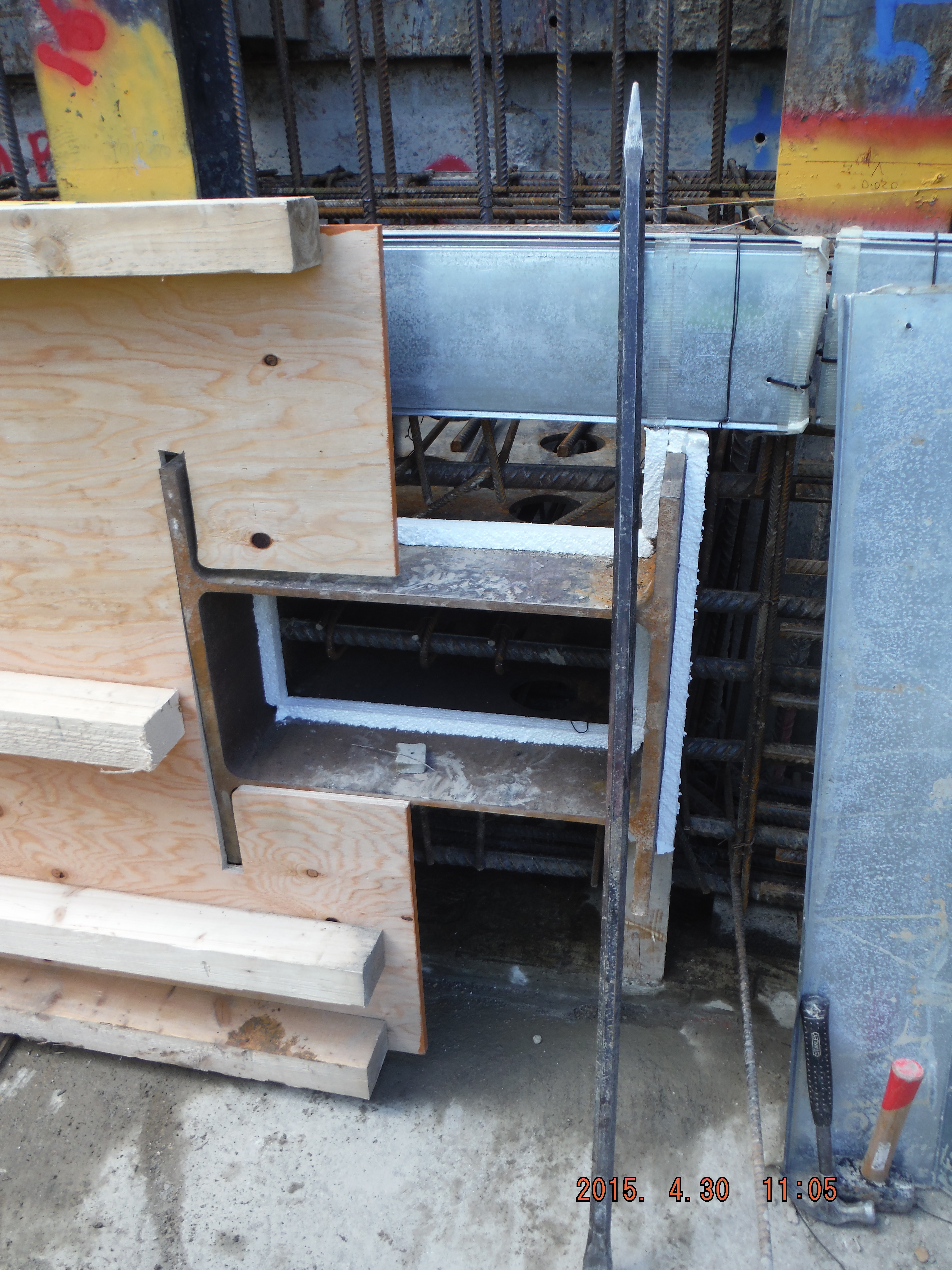
Polystyrene used as a 25mm rebate to enable the shear stubs to be burnt off after use and the concrete made good.
Pete – use of hirib below in a stop end. The expanded metal helps form a rough edge to make a joint for the next pour. This only works for Level 1 waterproof sections (see below).
Hirib stop end – mechanical means to form a cold construction joint eliminating the requirement for scabbling.
Delivery method. The method of delivery was via a rolling skip with tremie pipe and crane. This was used because 1. The crane was available, 2. There was no space to get a concrete wagon or excavator near to the beam.
Pumping was also considered but would be very expensive for a small pour (circa £12k for 1 day hire).
Delivery by skip actually meant the pour was very controlled (reduced pressures on formwork) and safe for the operatives doing the concreting because of its controllability.
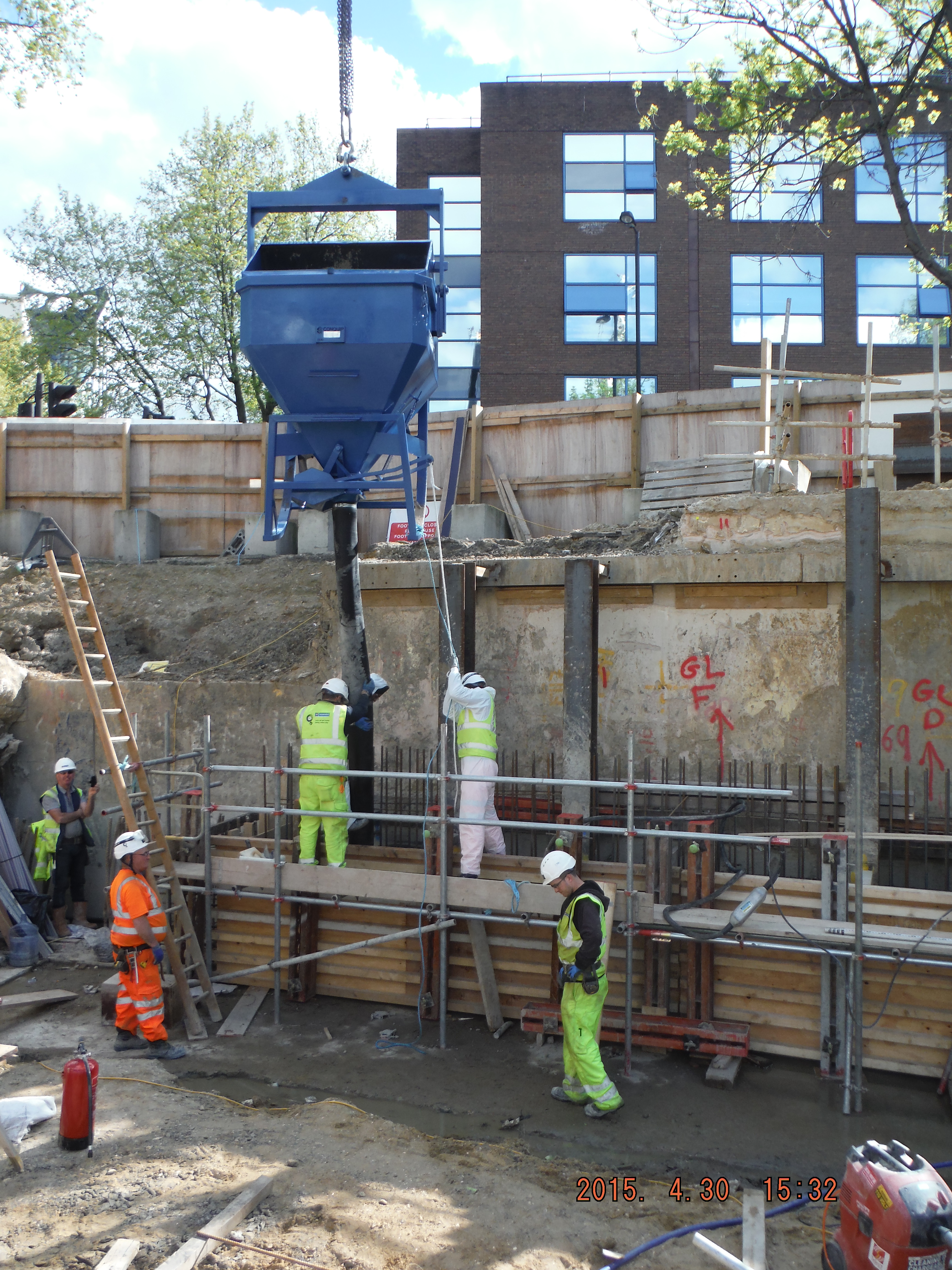
Concrete delivery by skip with 3m tremie pipe.
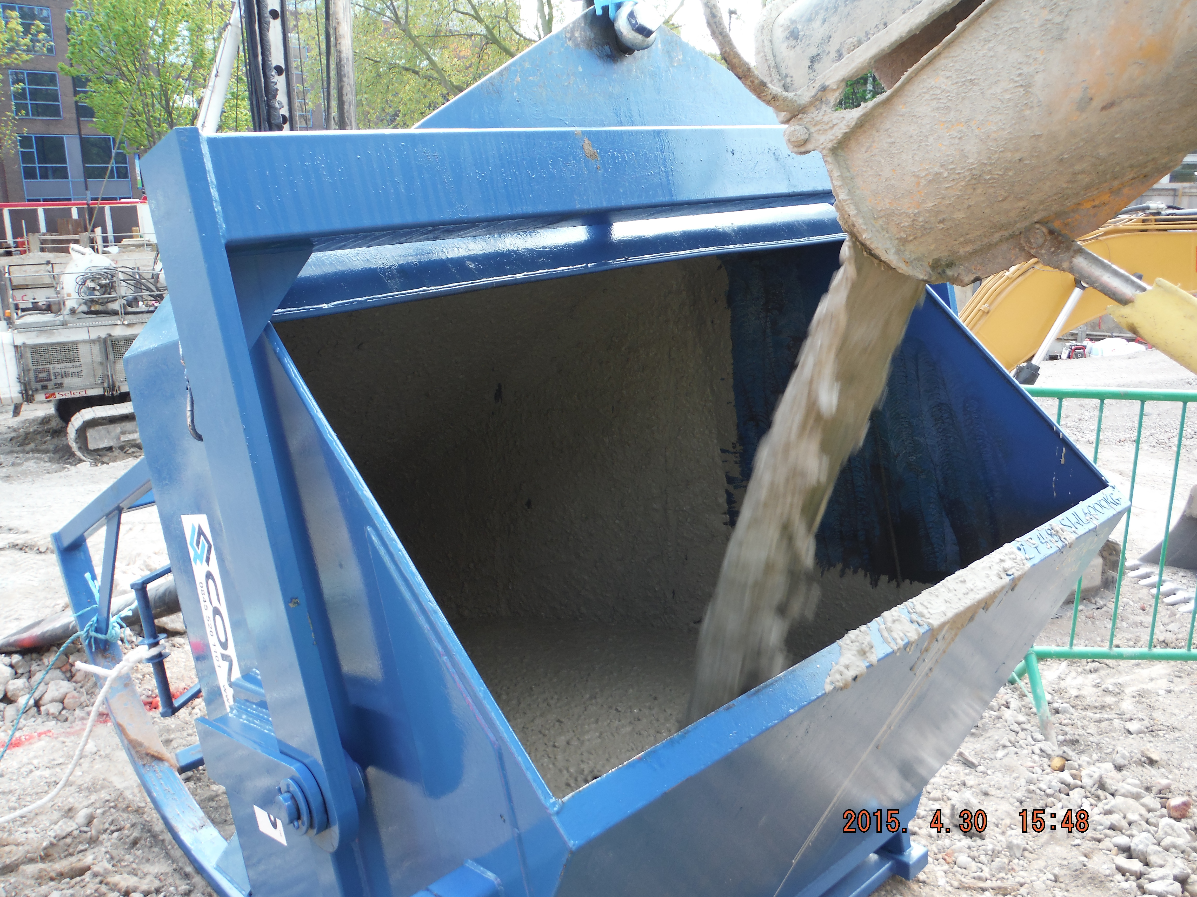
Rolling skip means it is easy to discharge into from the concrete wagon.
Curing. The top of the capping beam is going to have a retaining wall constructed on top of it, hence the starter bars. The inner side of the capping beam will form the start of the basement slab. Therefore half of beam needed to be retarded, half cured. The point of the retardant was to reduce the speed of curing to allow the beam to be jet-washed the following day in order to roughen the surface to make better interlock for the future wall pour.
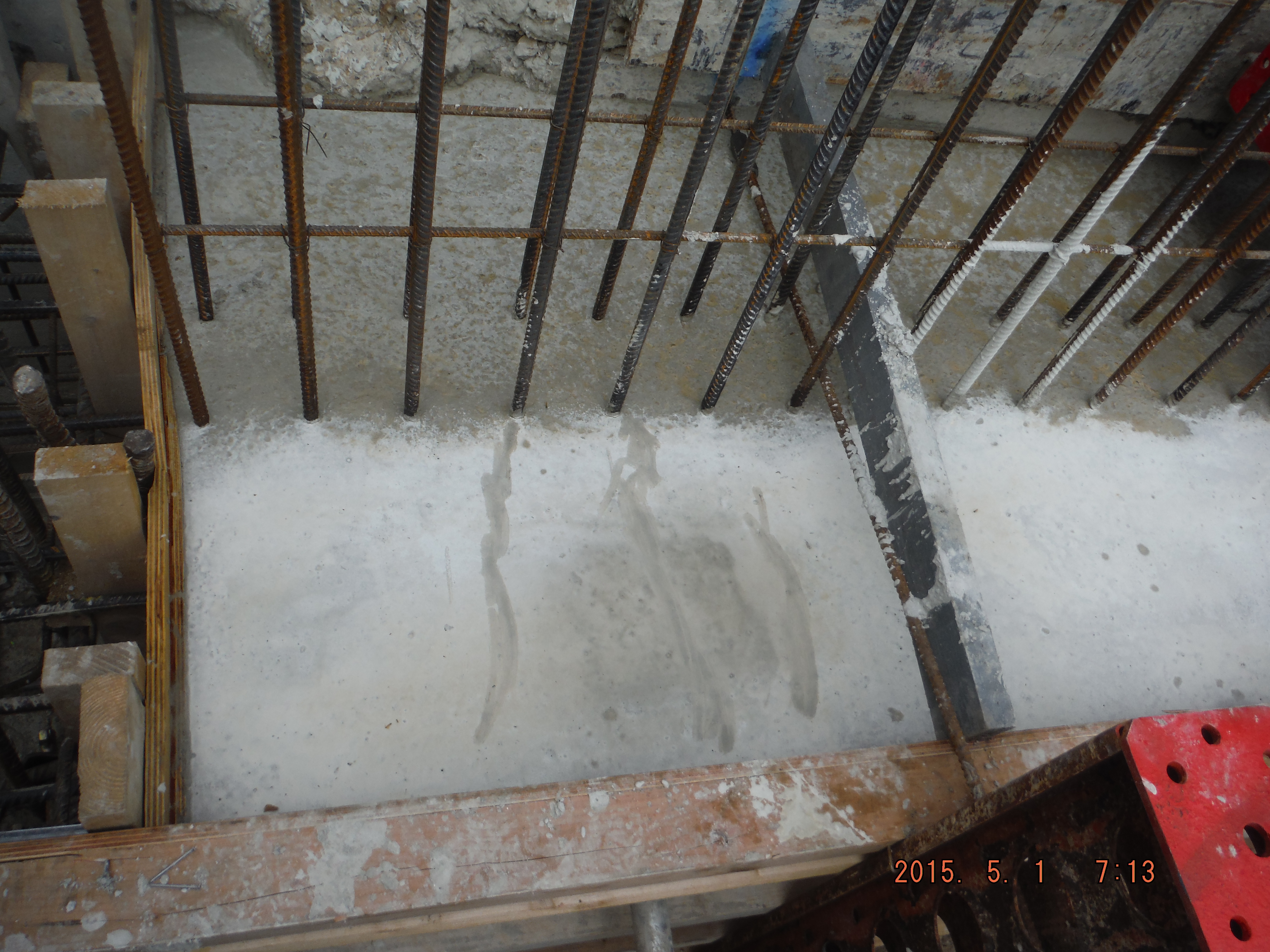
Near surface – cured for part of future basement level 1 slab. Far surface retarded for future retaining wall.
Cracks. The concrete mix and steel design is meant to help reduce cracking (maximum crack width allowable: 0.2mm), although only very limited trials have been done on this so it will be interesting to see what we get. The waterproofing requirement of the beam varies between level 1 (beading of water allowed on inside) to level 3 (completely waterproof). However crack width is limited to 0.2mm for the whole perimeter. The only difference is the level 3 sections are going to have a hydrophilic strip (between piles and bottom of capping beam) and an “Adprufe” additive in the concrete mix to make the beam waterproof.
It is likely non-structural cracks will form (which cause durability issues because of reinforcement corrosion) within a day of the pour. The cover has been set at 55mm which means the as cracks reduce in width with depth, the reinforcement should be protected. Applying curing agent to the beam aims to protect it from rapid drying out of the concrete and therefore reduce cracking. Before hardening of the concrete plastic cracks may well form due to either plastic shrinkage or plastic settlement. It looks as though plastic settlement around the reinforcement due to “bleeding” (water rising to the beam surface shortly after compaction due to heavier mix constituents moving down due to gravity) has already occurred, although very minor at this stage.
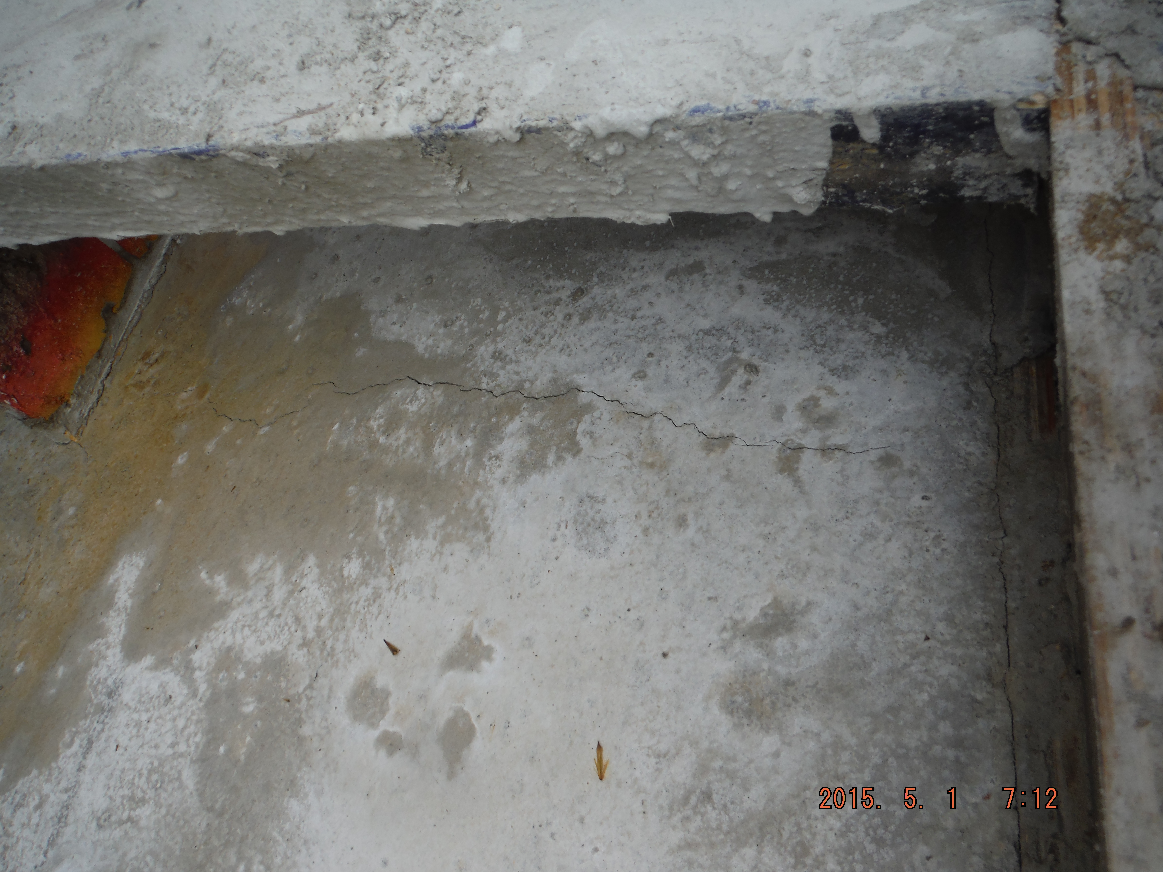
Plastic settlement crack forming over link reinforcement.
Time will tell regarding the growth or healing of the cracks and so I will monitor the situation after the bank holiday.
It is now a case of: underpin, break piles, reinforcement, formwork, concrete and repeat…
Site Two Fifty One – In the thick of It
Site Two Fifty One – In the Thick of It.

Capping beam steel erection.
I have mentioned before that one of my roles is the installation of the capping beam which runs the full perimeter of my site (180m). The steel for the first 35m arrived on Monday to culminate a design development of something I have been responsible for since arrival. The capping beam will have an in-situ wall sitting on it and a basement slab spanning from it. Additionally, for about 5 months, it will be used as a beam to prop off in order to excavate one storey down.
Groundforce propping plan (click to open pdf): 1728 101
So there are elements to the installation which have huge consequences if not correct.
Single shear stub.
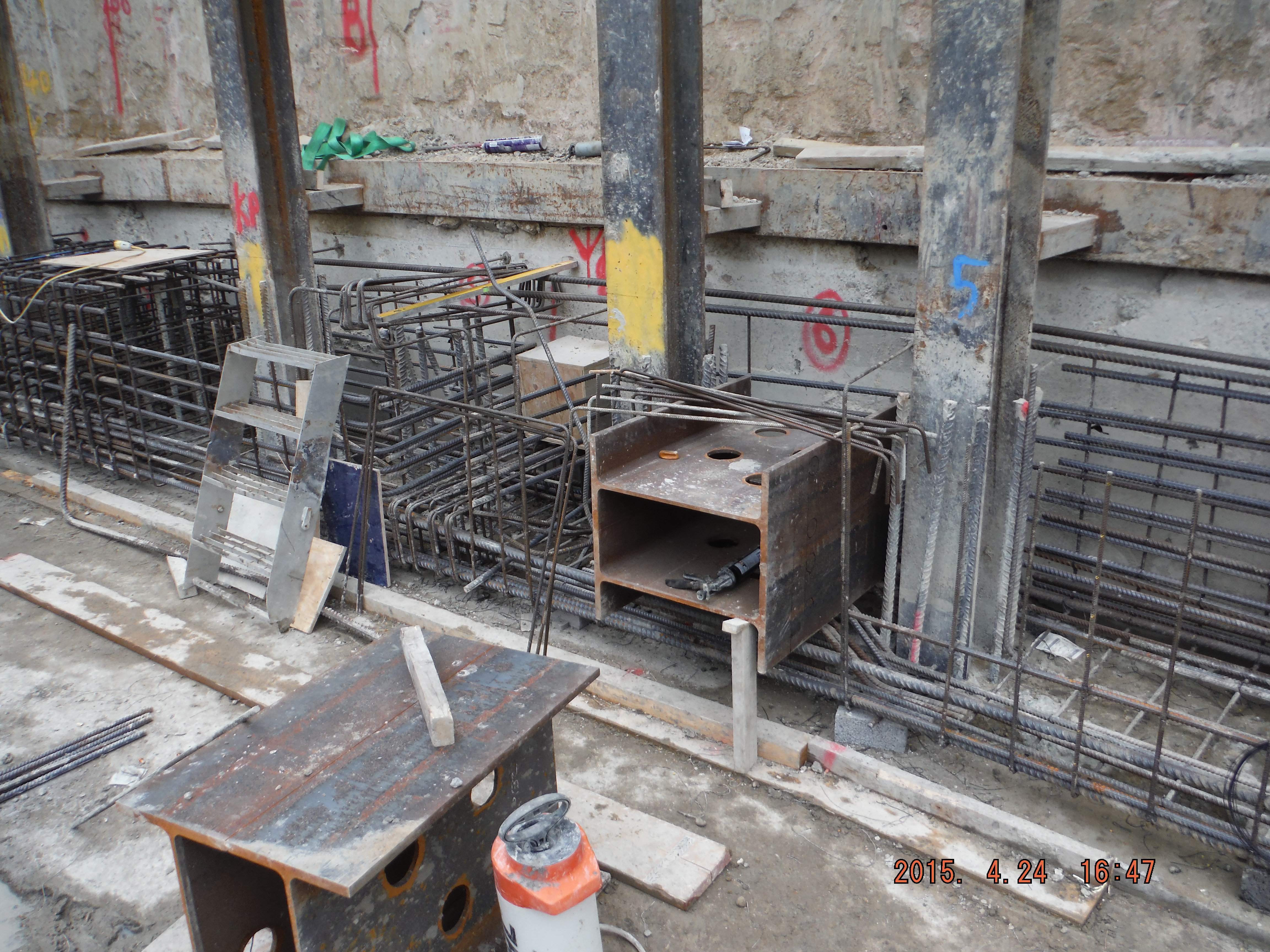
Double shear stub.
There is a drainage duct which protrudes through the beam and there are umpteen ‘king posts’ column sections retaining the old retaining wall behind.


Drainage pipe location (left). Bent bars around drainage position (right).
All in all, there is lots going on. The capping beam steel has been digitally modelled, which has 2 advantages. 1. It helps understand how it fits together and 2. The steel schedules are produced from it (Tekla software) which can be used directly by the steel supplier, rather than a person re-typing a pdf document.
As a task, perhaps initially seemingly pretty minor, there are actually numerous considerations:
- Sourcing of steel (Laing O’Rourke will only purchase from Europe although many steel suppliers source from China because it’s cheaper).
- Delivery method: pre-slung or stacked for slinging on site. Method of lifting (crane, excavator), LOAFs.
- Length of bars for working in congested areas (more lapping versus ease of installation).
- Stop ends (max pour size is 40m3.) Use of hirib to avoid scabbling.
- Prop end plate locations and bolt hole positions.
- Formwork design (yes concrete pressures for a 1.2 high beam is important).
- Resource management (lead times, timber, concrete, steel, tools and equipment)
- Concrete – waterproofing.
- Future slab starter bars (kwika-strip).
- Labour management (steel fixers, carpenters, labourers).
- Dewatering (bottom of blinding is at ground water level): sump pumps, discharge permits, siltbusters.
- Concurrent adjacent activities: sheet piling, CFA piling, muck away, welfare establishment, ramp movement).
Reflections.
So far so good, just. It is pretty much construction by just in time design. This means I am getting drawings hours (sometimes minutes) before they are needed on site. This means being familiar with bar mark notation, real detail in why shear links are here or there is key. In reality there are good people to answer my RFIs (temporary works department, Groundforce shorco, digital engineers, steel supplier (Midland Steel), the designers (Waterman)) but there are always pressures to deal with on site. Line and level of shear stubs for props, drainage duct location and invert levels and actual position of the capping beam itself.
It is hugely rewarding to see something you have been involved in start come to fruition, albeit the first big test will be my shuttering design! The concrete pour is planned for next week so no doubt the grey stuff will soon feature.
I think running the execution of the capping beam is a great chance to learn how things work before the significant challenge of the basement slab (entire site) comes along.
In other news, there has been the first working load test on the office piles and a section of site has had sheet piles installed to act as a replacement retaining wall (where the old substation was).

Pile working load test (as Pete predicted!). No further details yet.
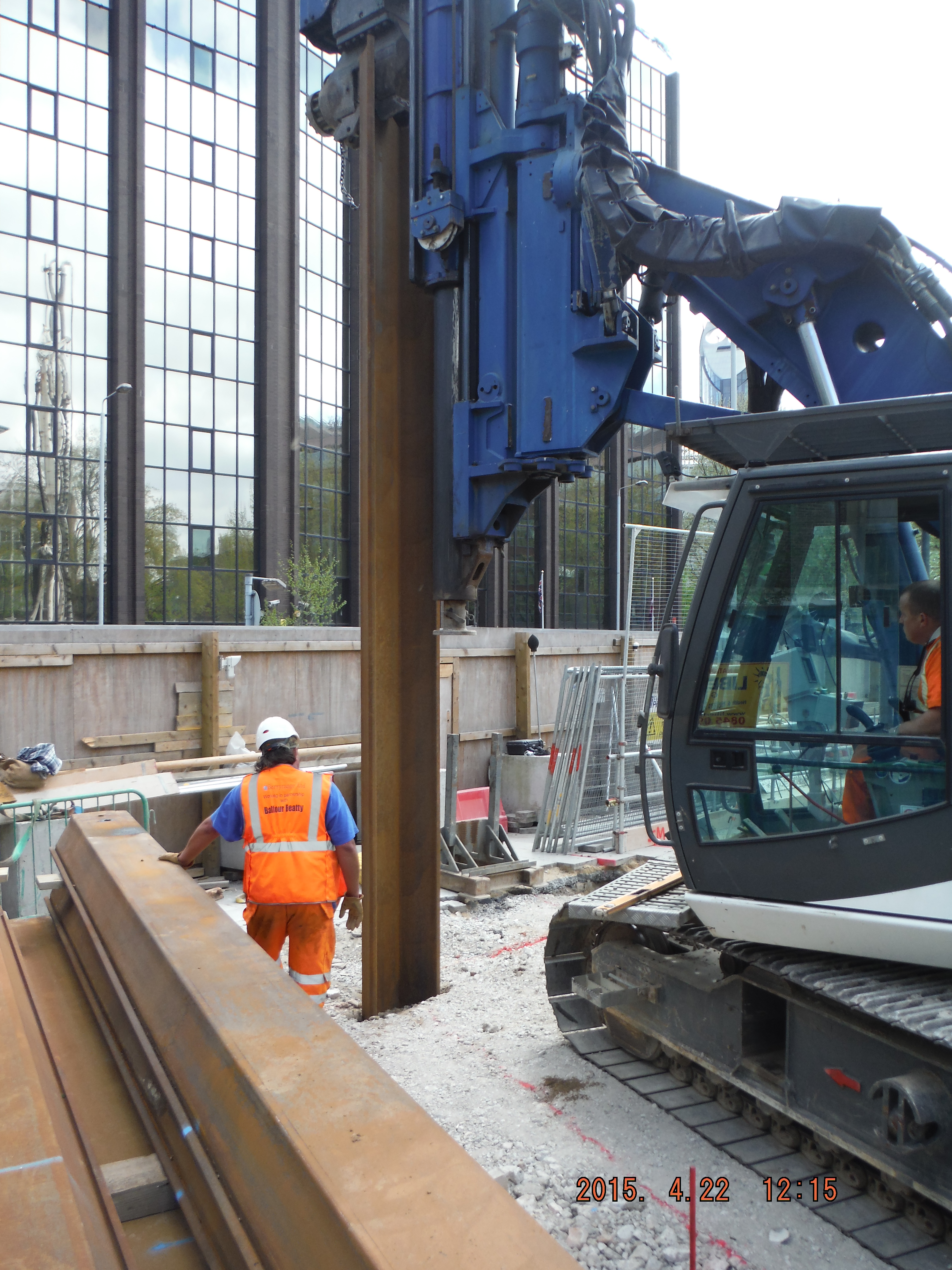
Rotary bored (tick), CFA (tick) and now a bit of vibratory sheet piling.
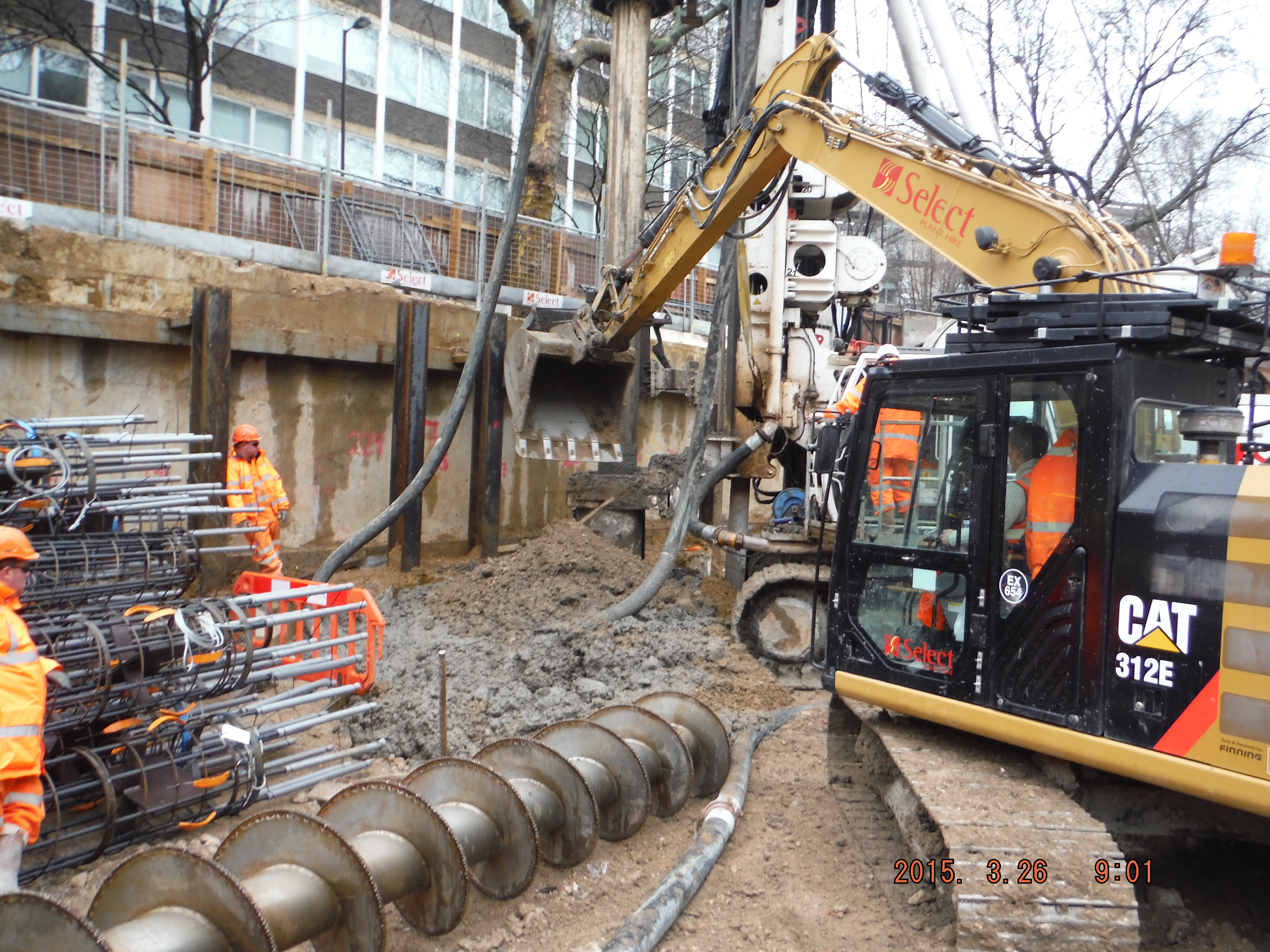
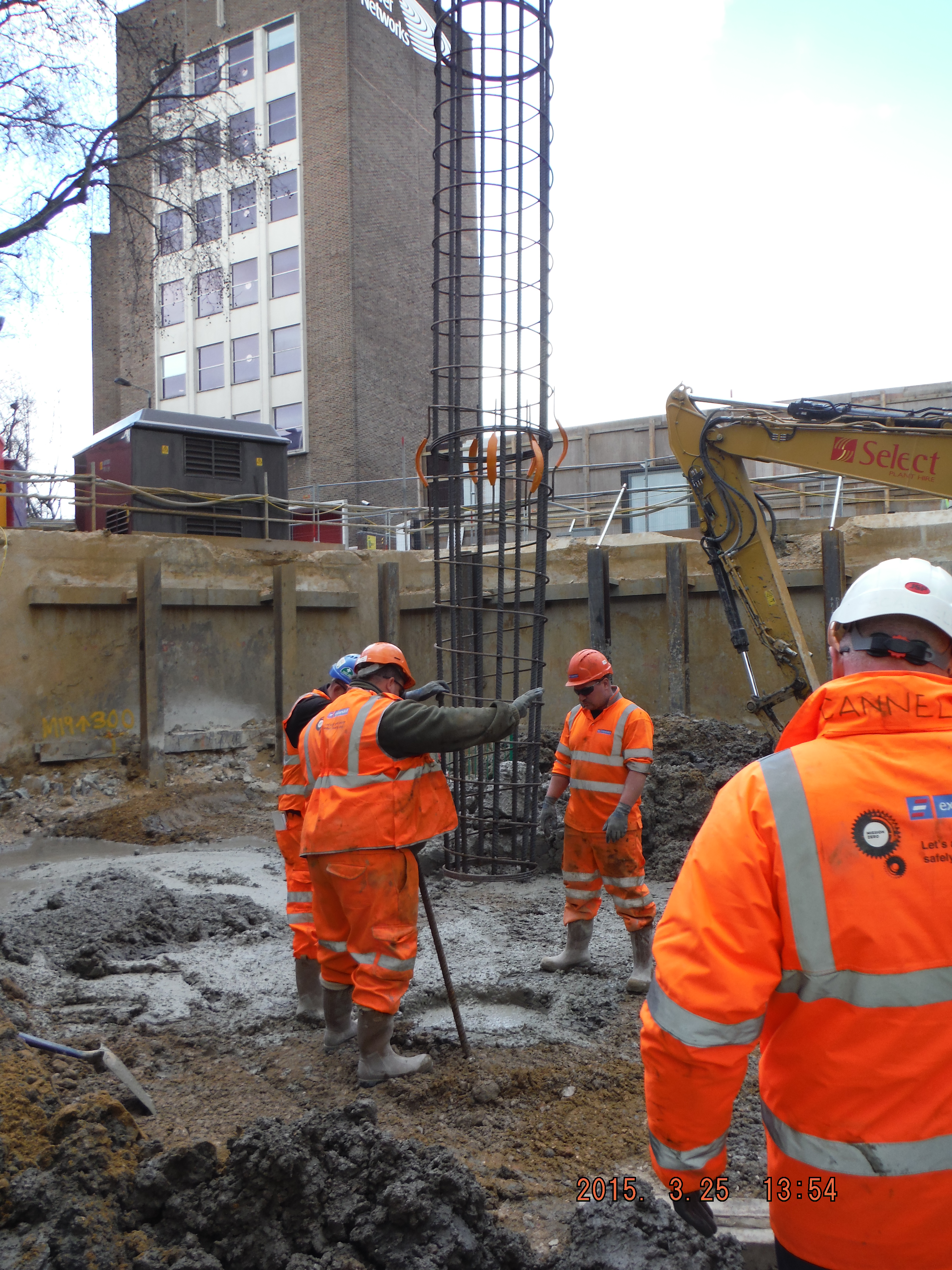
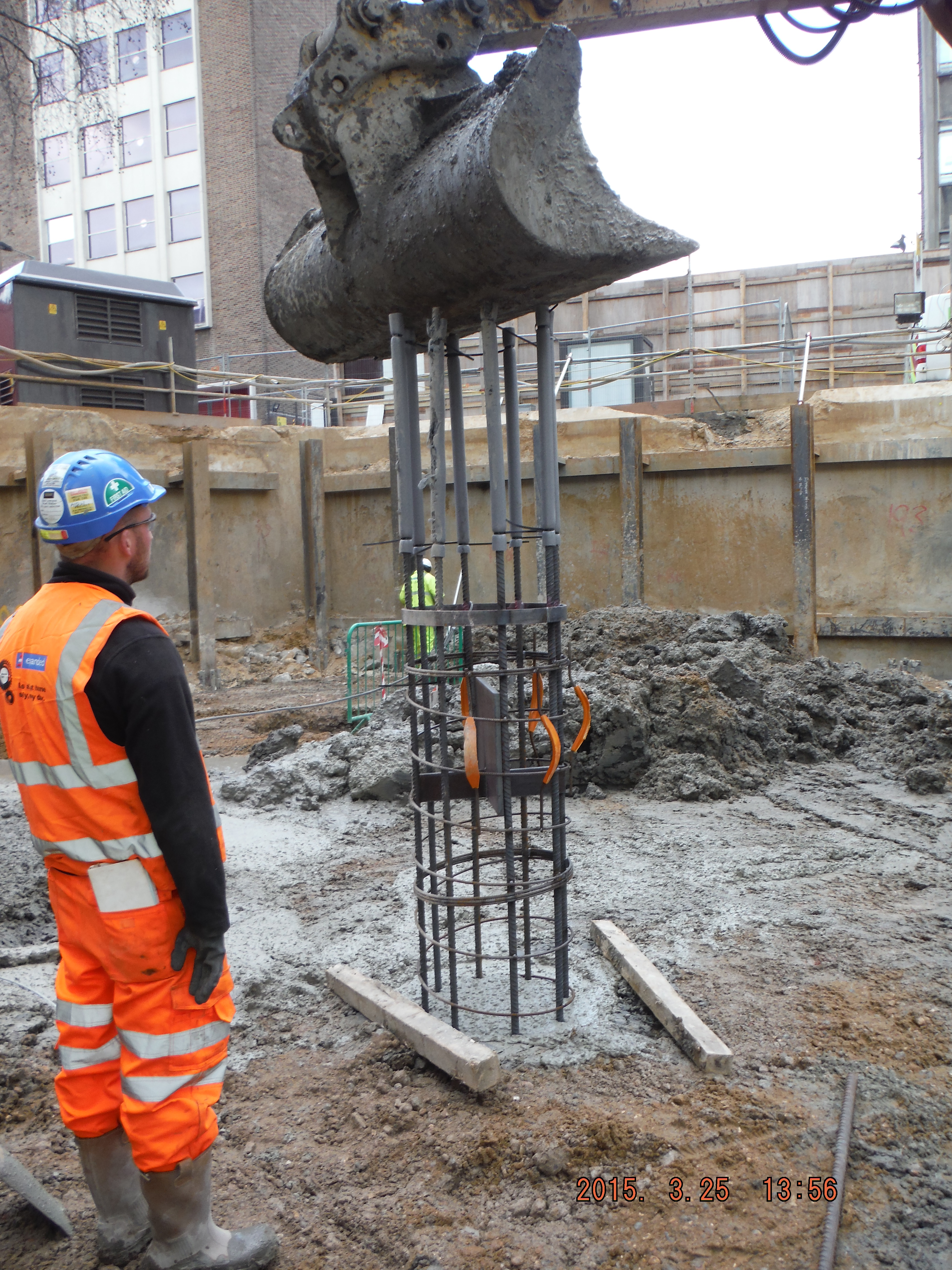
Pile Breaking
Site Two Fifty One
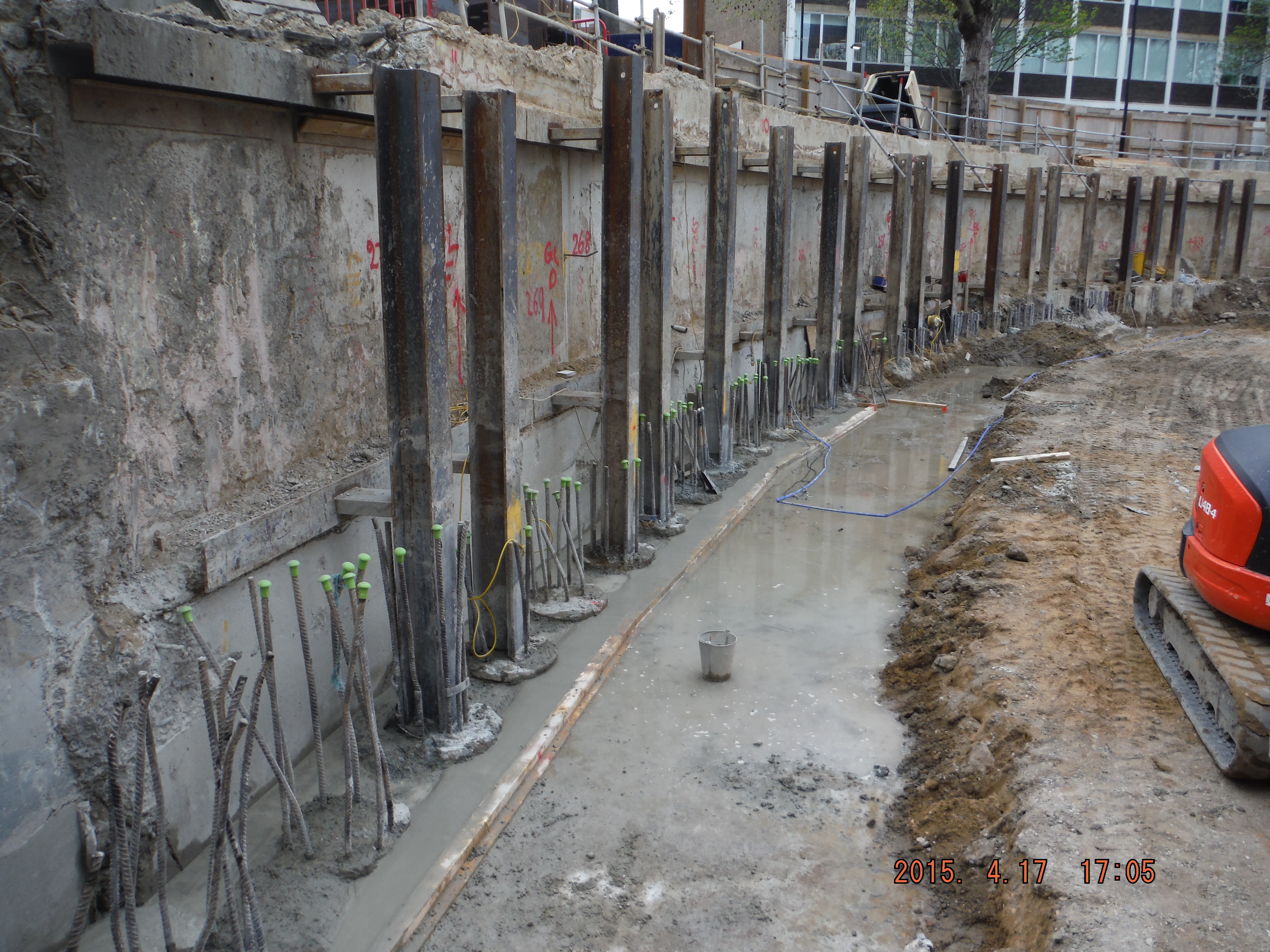
It has been the subject of many a previous blog but perhaps the reality of breaking C37 concrete away from pile reinforcement is only just becoming obvious now I see it first hand.
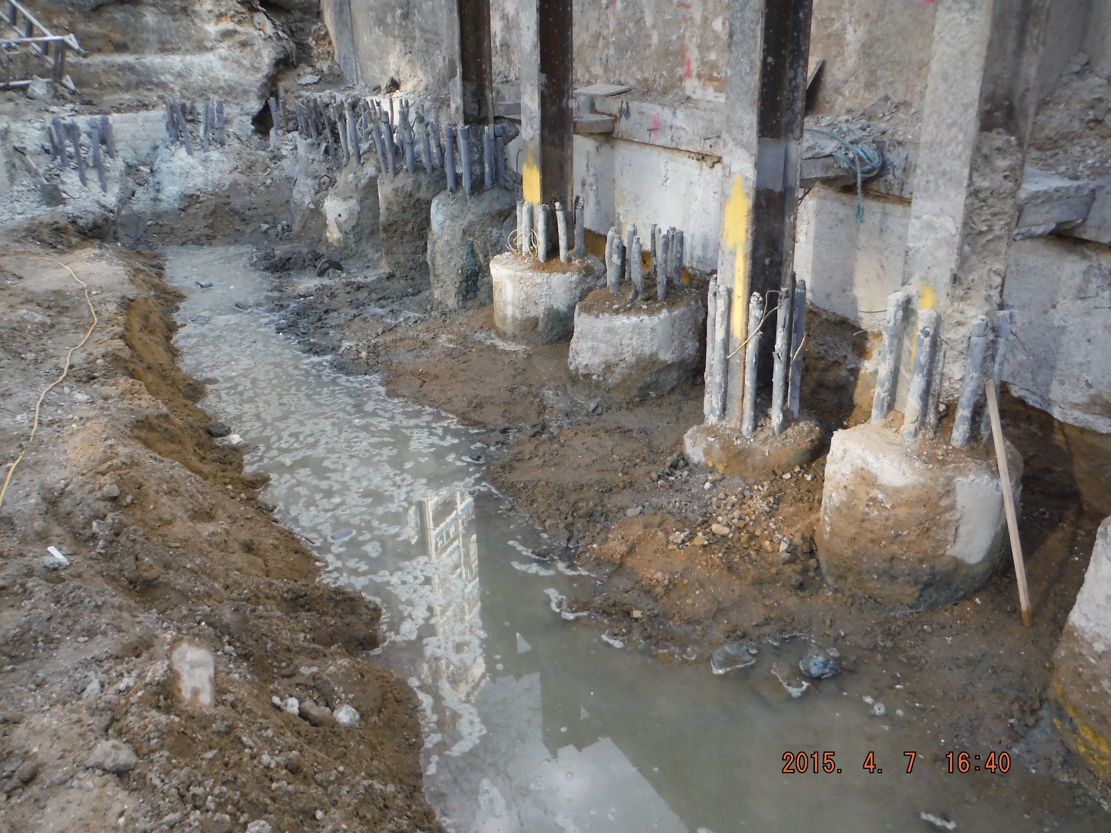
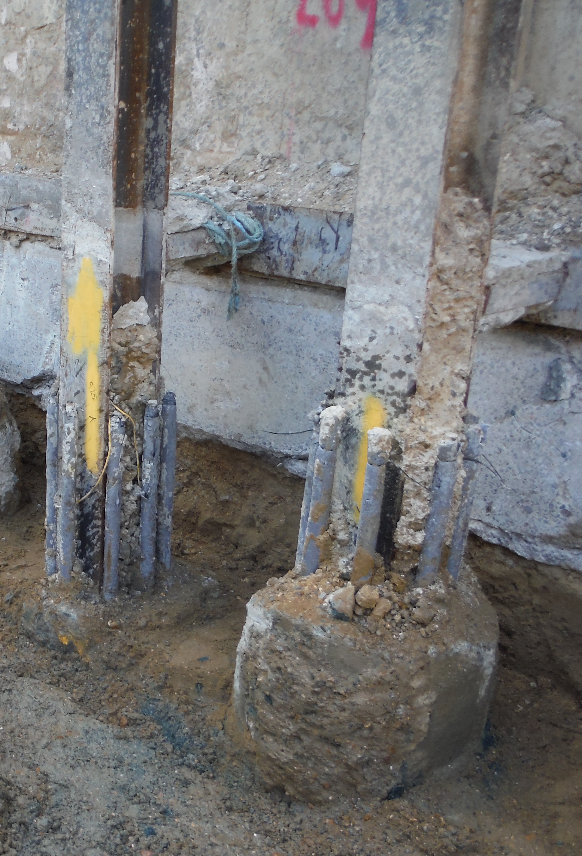
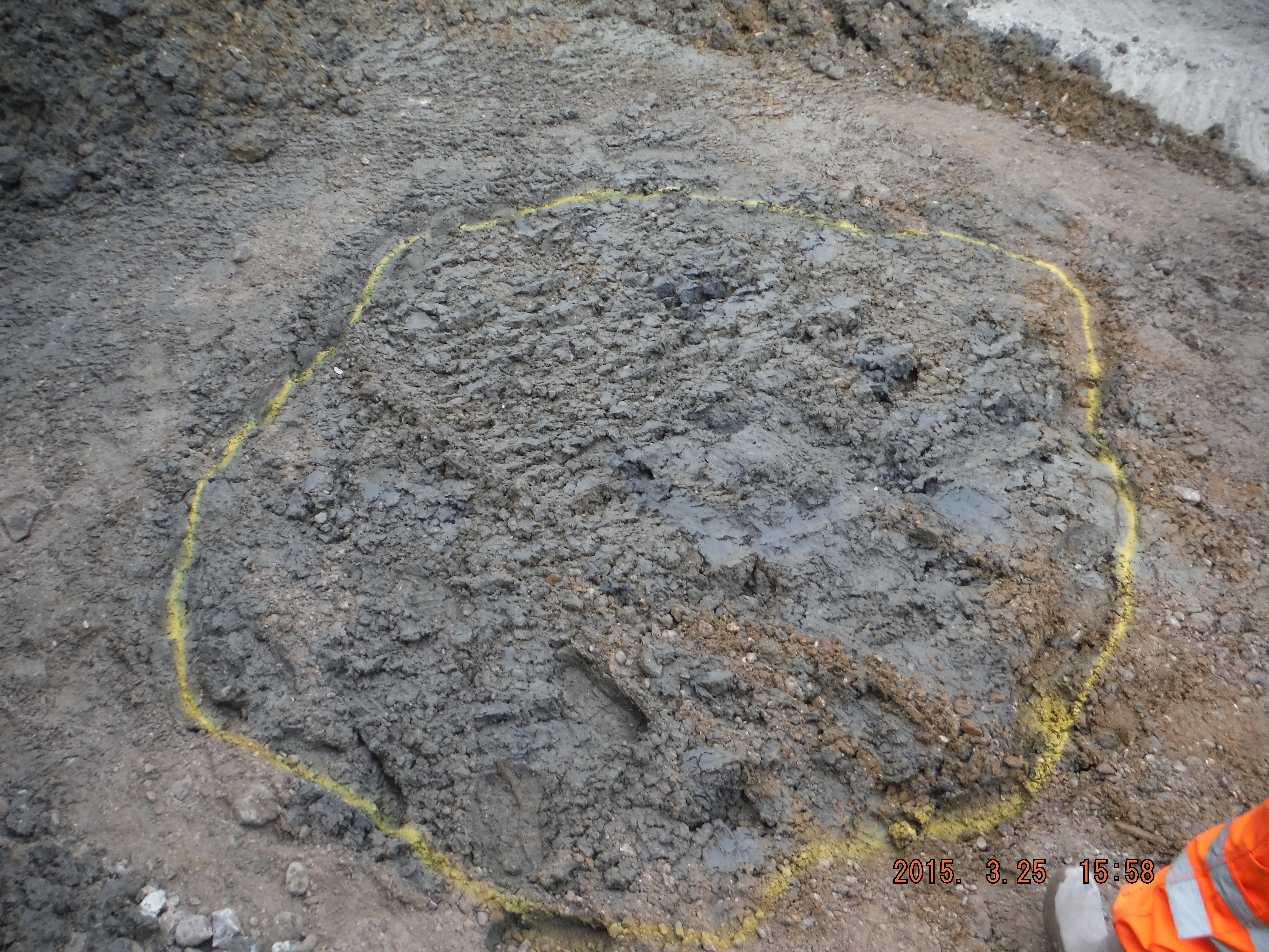
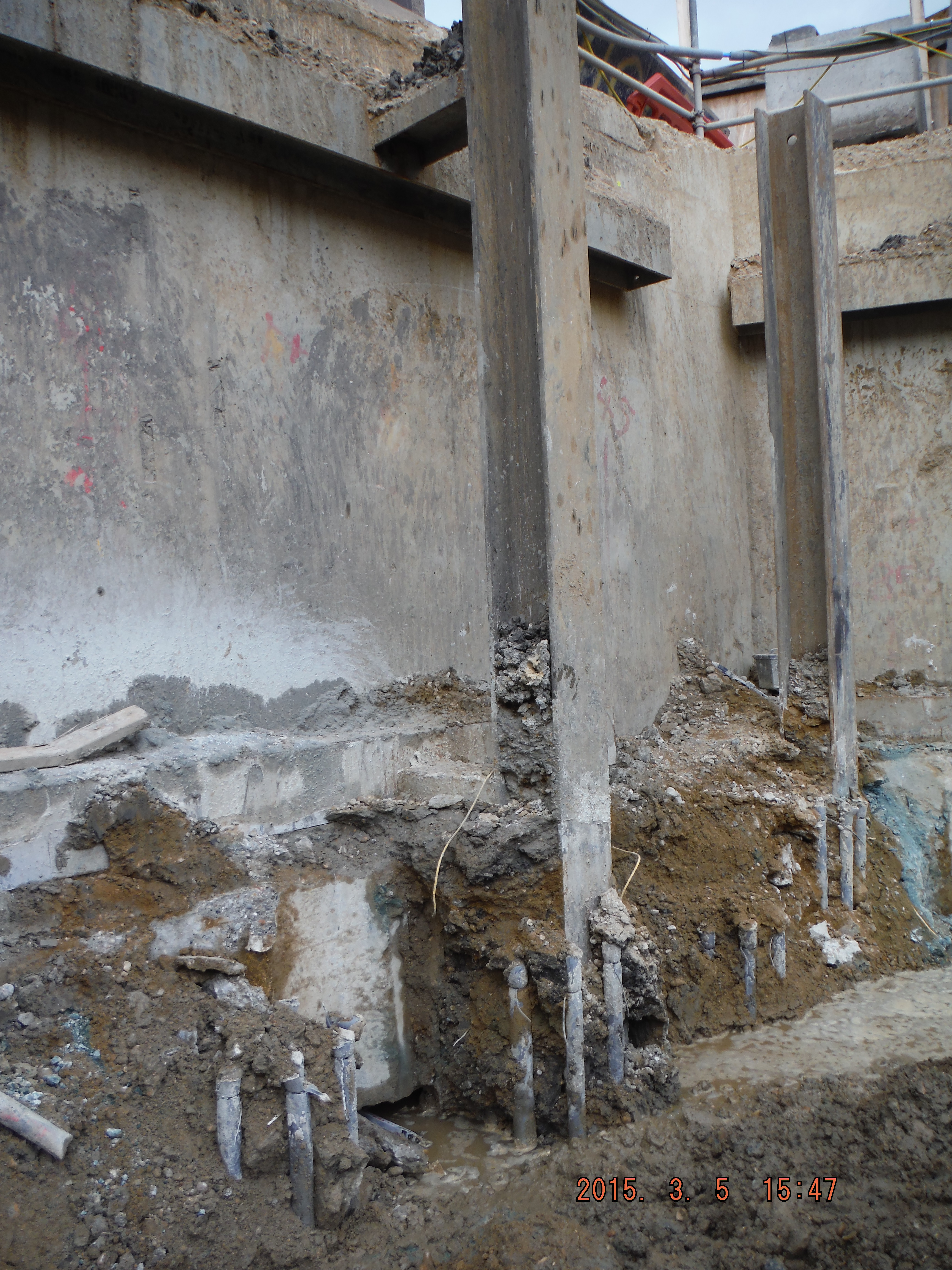
Male piles protruding well above cut-off level (see yellow spray bottom right).
Rotary bored piles which are cased allow piles to be cast to a cut-off level pretty closely. The secant pile wall must embed 75mm into the capping. This is a cut-off level of -1.105m AOD. The pile method was changed from rotary bored to CFA because CFA would enable deeper piles to be constructed. The deeper piles are tower and office bearing piles, not secant wall piles, however due to the constrained site size not all of the perimeter wall could be exposed to do the secant wall with the rotary method.
So what? The secant wall is being done with CFA. The problem? The pile platform level is at +0.150m AOD. This means piles are being cast 1.255m higher than is required because CFA piles can only finish at ground level. The consequence of this is that over a metre of concrete is having to be broken out.
CFA pile with king post (embedded 3.5m into pile), cast at the pile platform level (1.255m above cut-off level).
I started the capping beam on 7 April with a foreman, mini excavator, 2 labourers and a carpenter.
Task 1: removal secant pile guide wall, Task 2: underpin existing retaining wall, Task 3: break piles to cut-off level. Excavator used to remove bulk of concrete.
2 weeks on we have prepared a section about 30m in length, and have not started steel fixing, formwork or concreting. The capping beam length is 180m long, therefore this could take some time (12 weeks, programmed for 7 weeks, albeit not on the critical path). The options are plentiful but what is becoming more apparent is the consequence of what seemed to be a sensible decision (change from rotary to CFA piling method) is now only fully realised and understood.
Further complications: Temporary Works versus permanent works.
The Designers (Waterman) have designed the capping beam for the permanent case (mostly bending vertically). Clearly they know we are going to excavate down another storey, but the reinforcement for the temporary props is not down to them to design.
The Temporary Works Department have added significant extra side bars to account for the props. In some cases this amounts to 8 x H32 compared to 6 x H16.
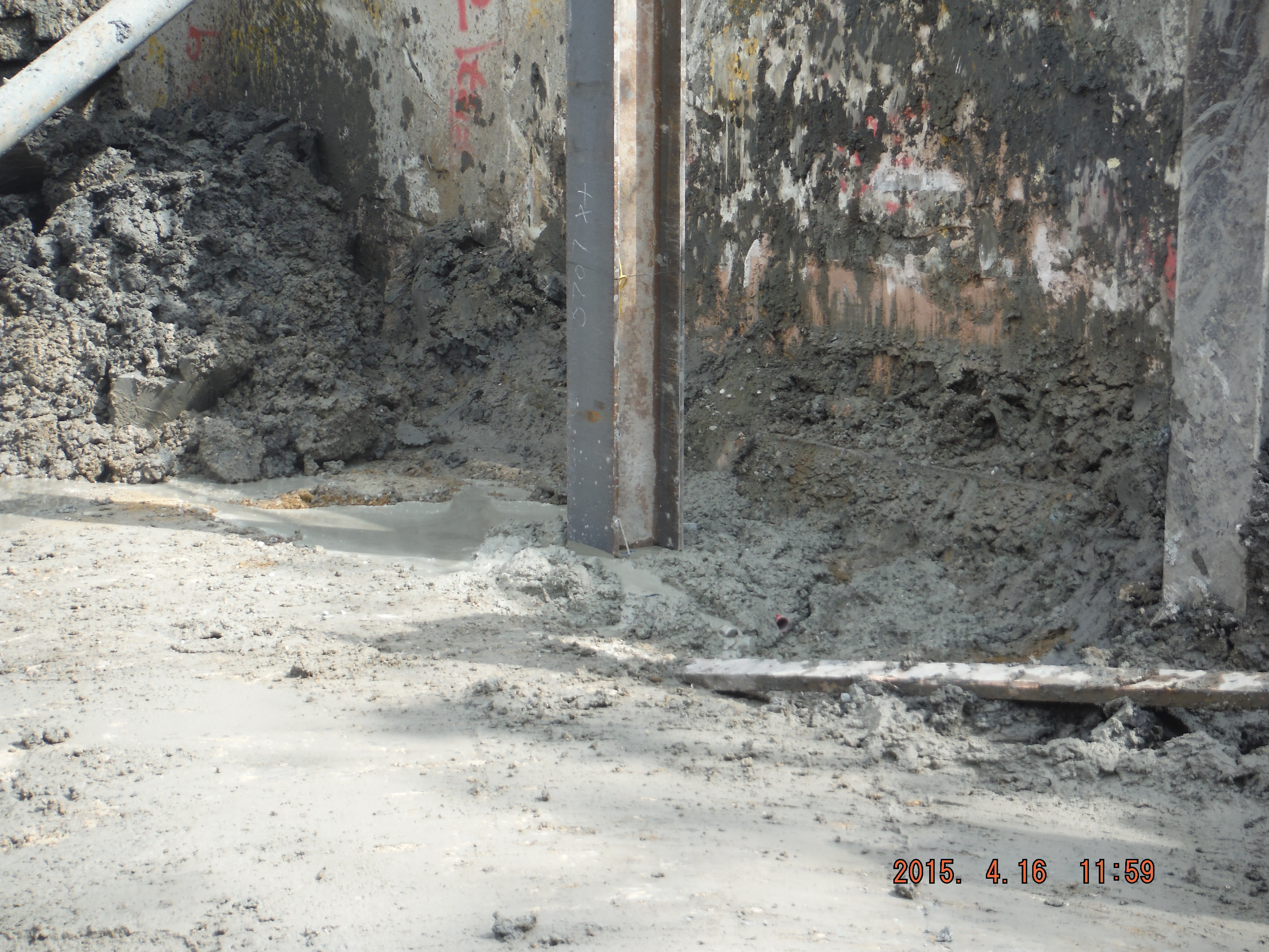
The temporary works situation (king posts propping old retaining wall) sees the vertical column sections (king posts) embedded into the piles within the pile reinforcement. This is to prop against the wall behind to act as a cantilever retaining wall.
King post embedded into male pile adds to the difficulty of removing concrete.
Now break concrete from the piles with column sections and pile cage reinforcement in the way! This is all doable and I have been careful in selecting a tool which does not give you white finger after 5 minutes use (such as air compressor type breakers). This has included finding Hand Arm vibration limits for the Hilti TE1000 breaker and use of the HSE website. Turns out that the action limit is 4-hours 44 minutes trigger time. So what – a minimum of 2 people have to do the breaking. Add in some rest periods and only account for actual “trigger time” and that specific piece of equipment is fine to be used each day.
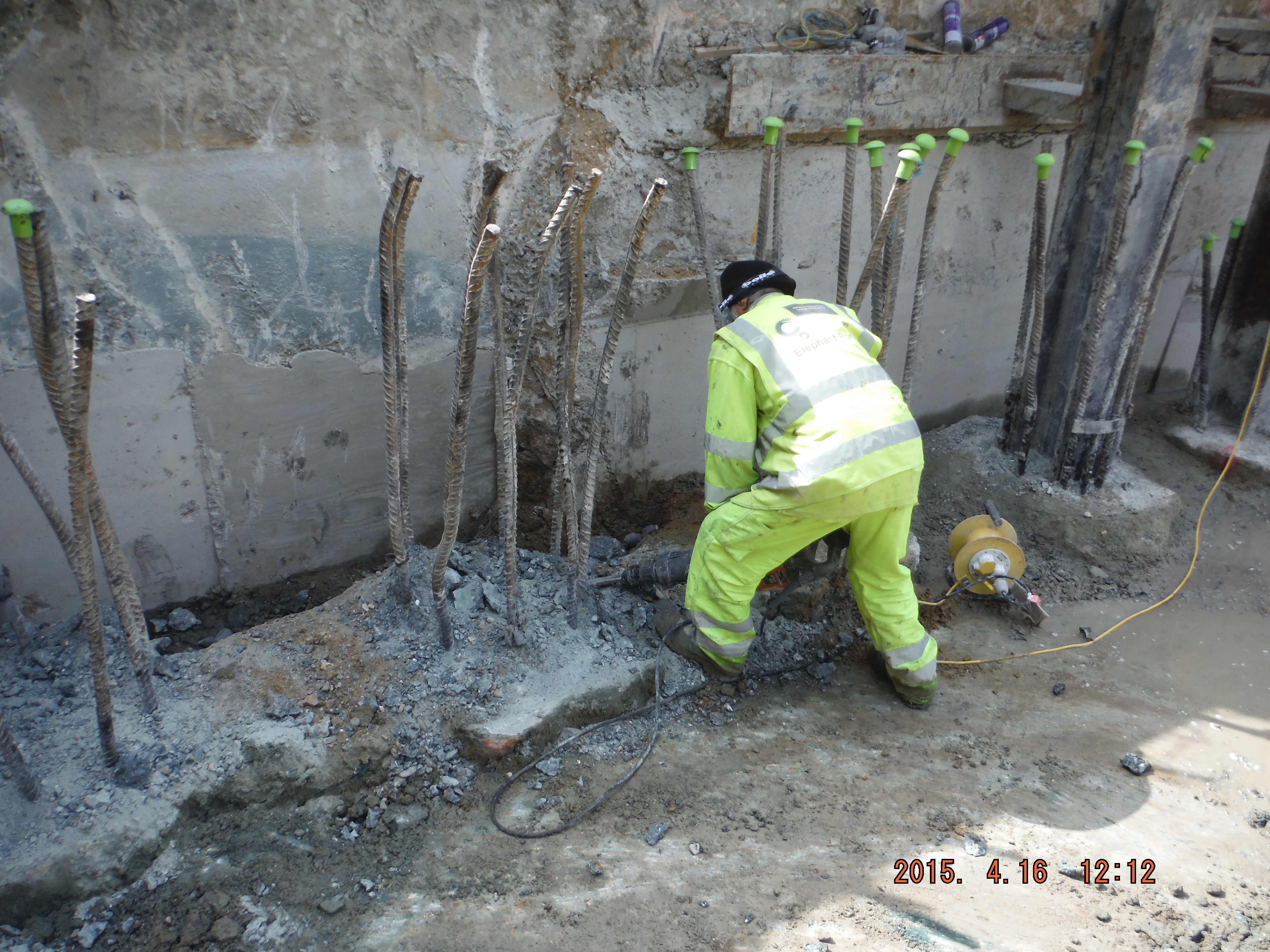
Breaking down the piles with a Hilti TE 1000.
Luckily the problem has become apparent before all of the secant pile wall has been completed. Therefore we will try and do something to reduce the utter nause of pile breaking.
Options:
1. Dig/ladle away wet concrete before it cures – sensible but that means putting 2 labourers close to the pile rig auger as it moves onto the next pile and as I have commented before the whole area is flooded in a slurry of wet concrete and clay.
2. Attach void former to web of king post to stop concrete even forming in the web.
Void former to reduce amount of concrete to be broken.
King Post with void former.
3. Suck out the concrete from the piles with a special concrete Hoover (apparently they exist).
4. Do nothing and head for the HAVS assessment.
Clearly the post pour options that exist are a bit trial and error and will involve an element of faffing about, however 20 minutes ladling some concrete out of the top of a pile compared to 2 weeks of chiselling it out is much preferred.
What I will take away from this is firstly to explain the importance of designing pile cut off levels and the consequence of not being able to execute the design. This might be to communicate the hazard through drawings and possibly the specification so that the contractor may mitigate the hazard before it is too late and the piles are cast.
Slow progress – Piles broken to cut-off and blinding concrete complete 10 days after starting.
This blog subject will re-emerge in about July 15 when the excavation of the basement is complete and the ground bearing piles need to be broken down (hence submerging pile cage reinforcement).
Now for steel fixing and remembering what Richard taught use about steel reinforcement schedules!
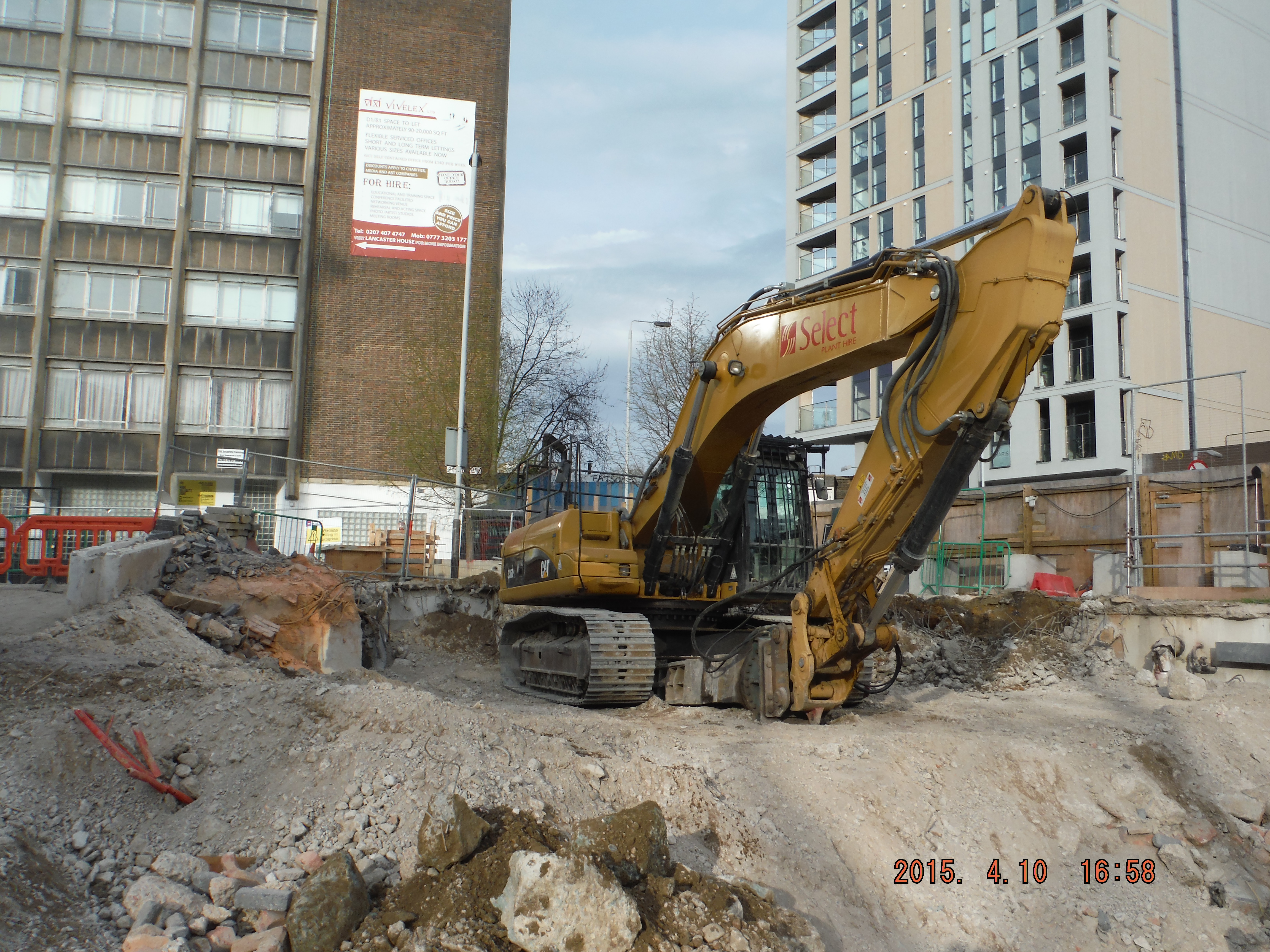
Site Two Fifty One – General Update
Site Two Fifty One – General Update
This week I thought I would blog generally about site activities taking place to give a feel of what I am doing. Main activities are: sub-station demolition, preparation for the capping beam installation, office ground bearing piles (CFA), pile mattress construction for a small section of sheet piling and the most laborious task of all, welfare establishment. My focus is on the capping beam, although when the project manager and project engineer are off-site my responsibilities tend to extend a little further, in fact, I am not sure where they stop!
All the activities themselves are fairly low level (no multi-span bridge beams for example) but the planning, co-ordination, resourcing and commercial aspects as a whole make for a varied experience.

Old sub-station at top of access ramp
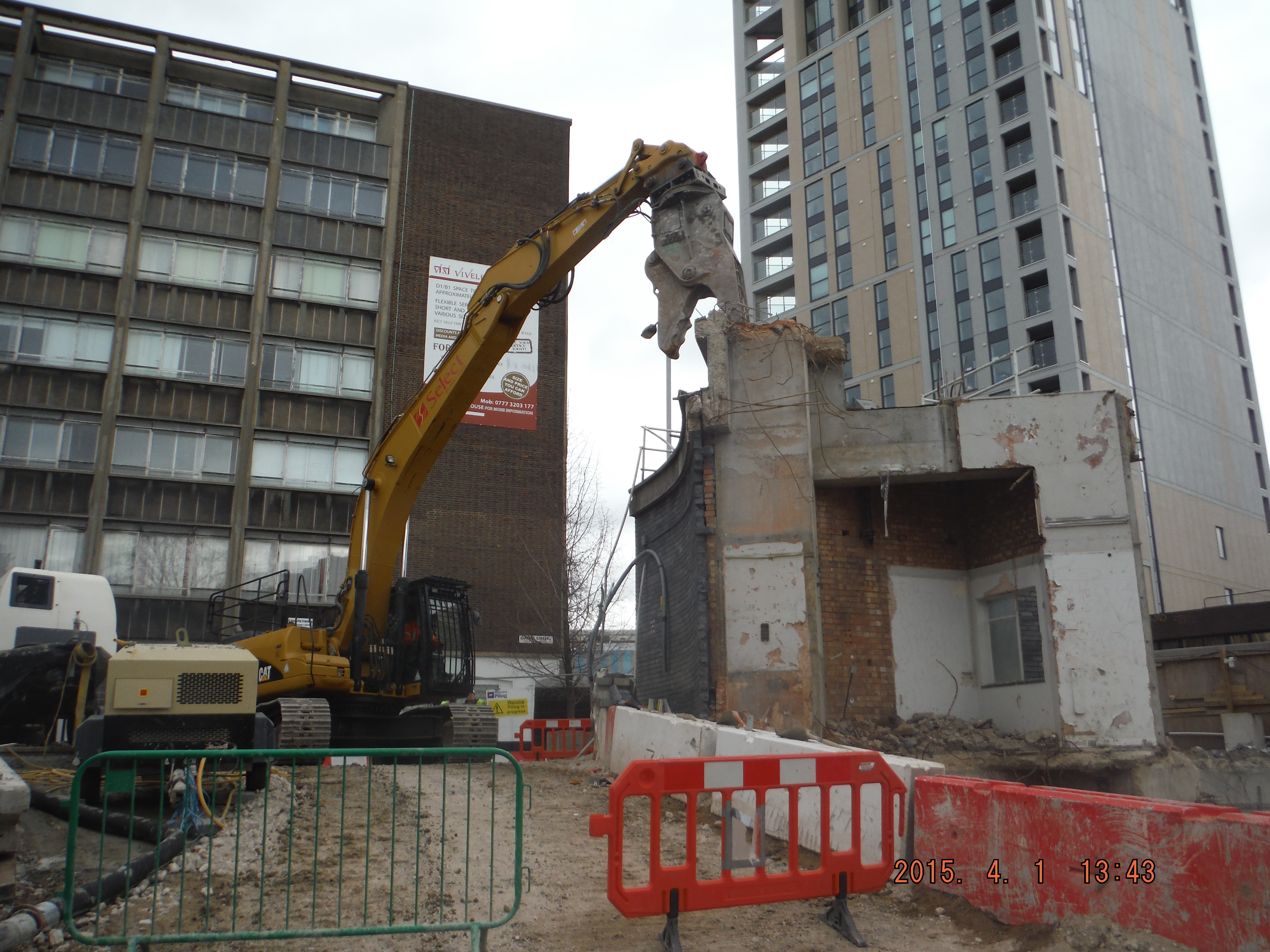
Demolition of the old sub-station begins
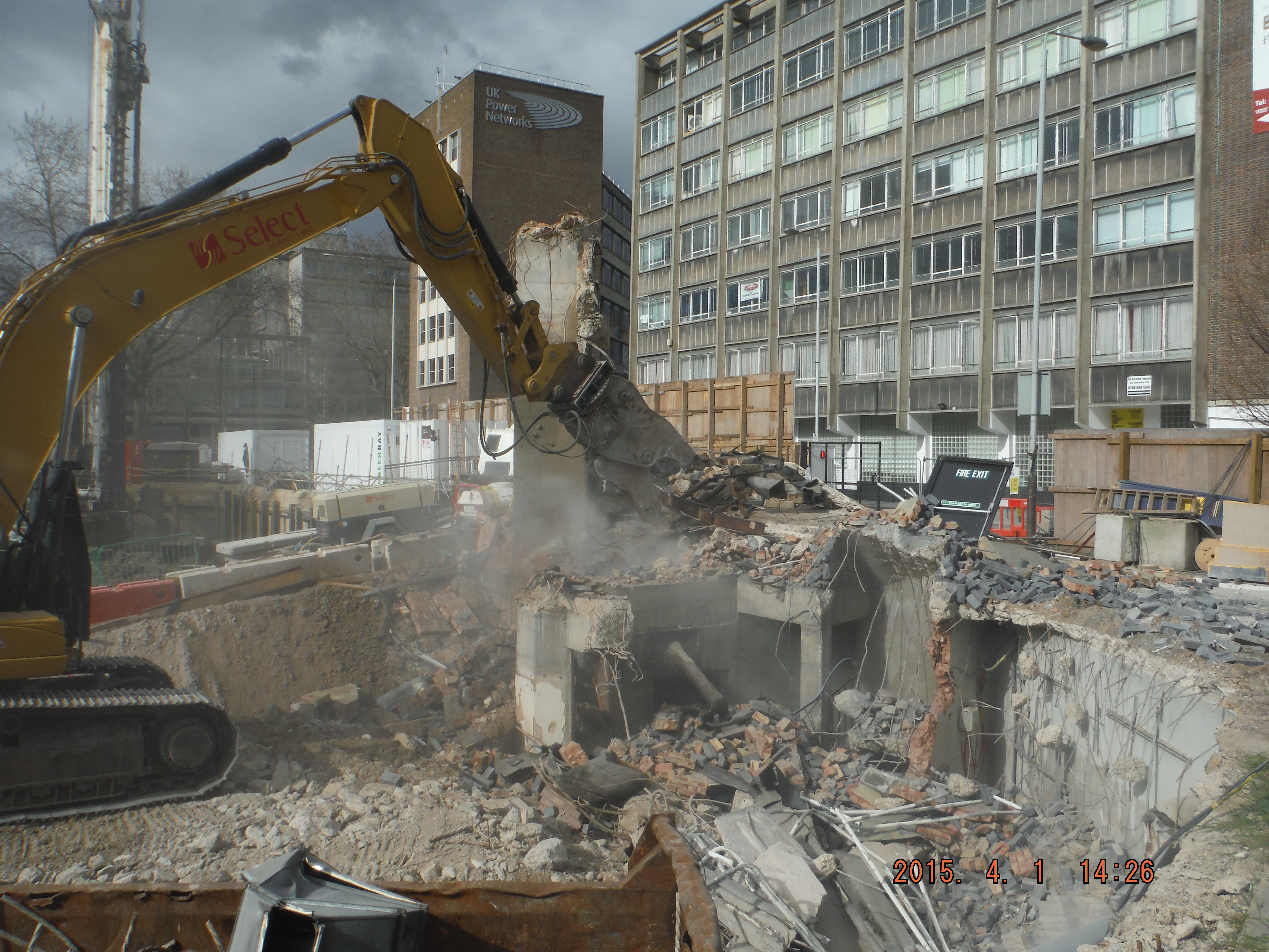
and finishes pretty soon afterwards

Breaking of piles to cut off level

Underpinning the pre-existing wall
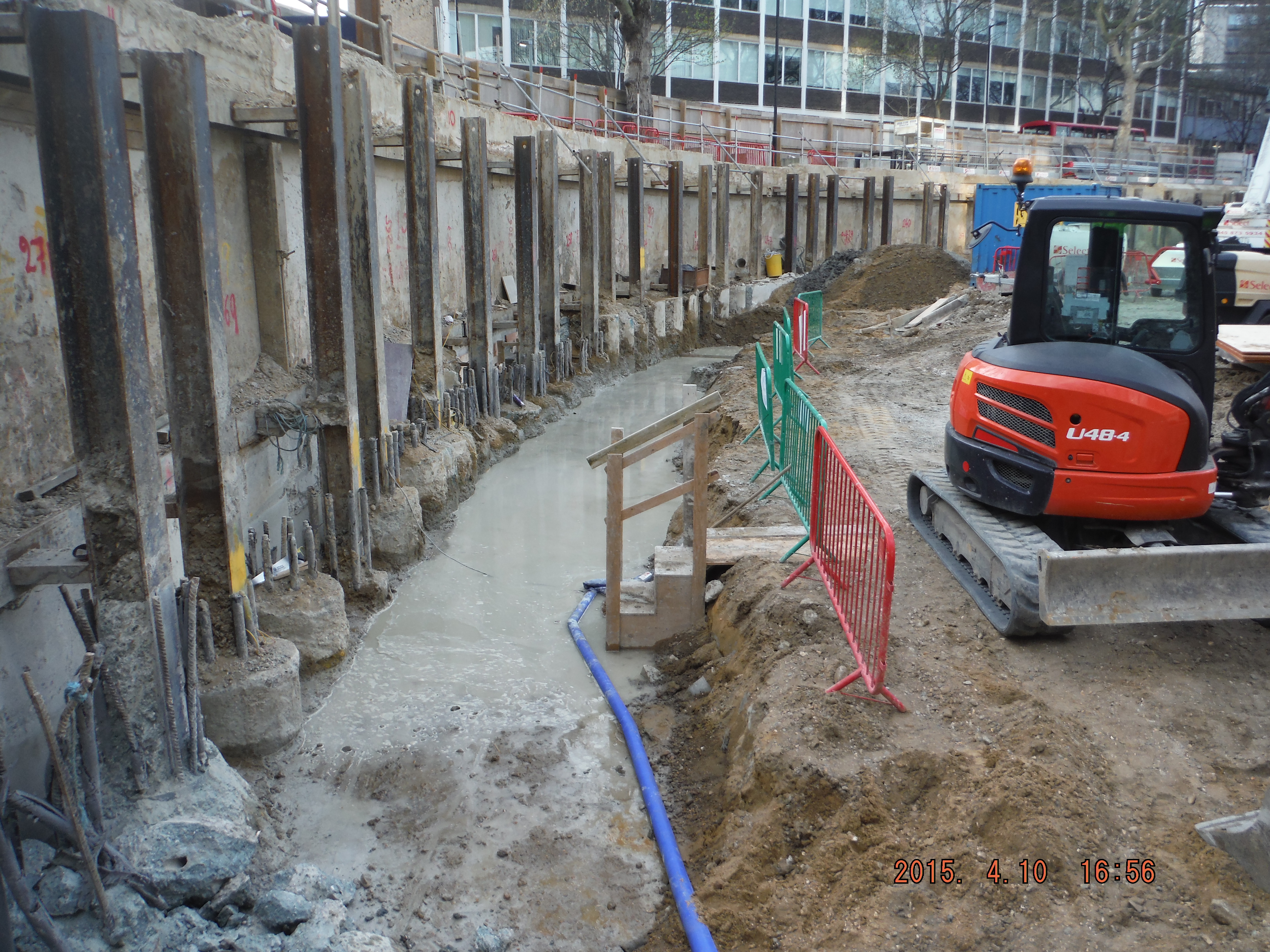
Preparation for the capping beam
Piling continues at much improved rate
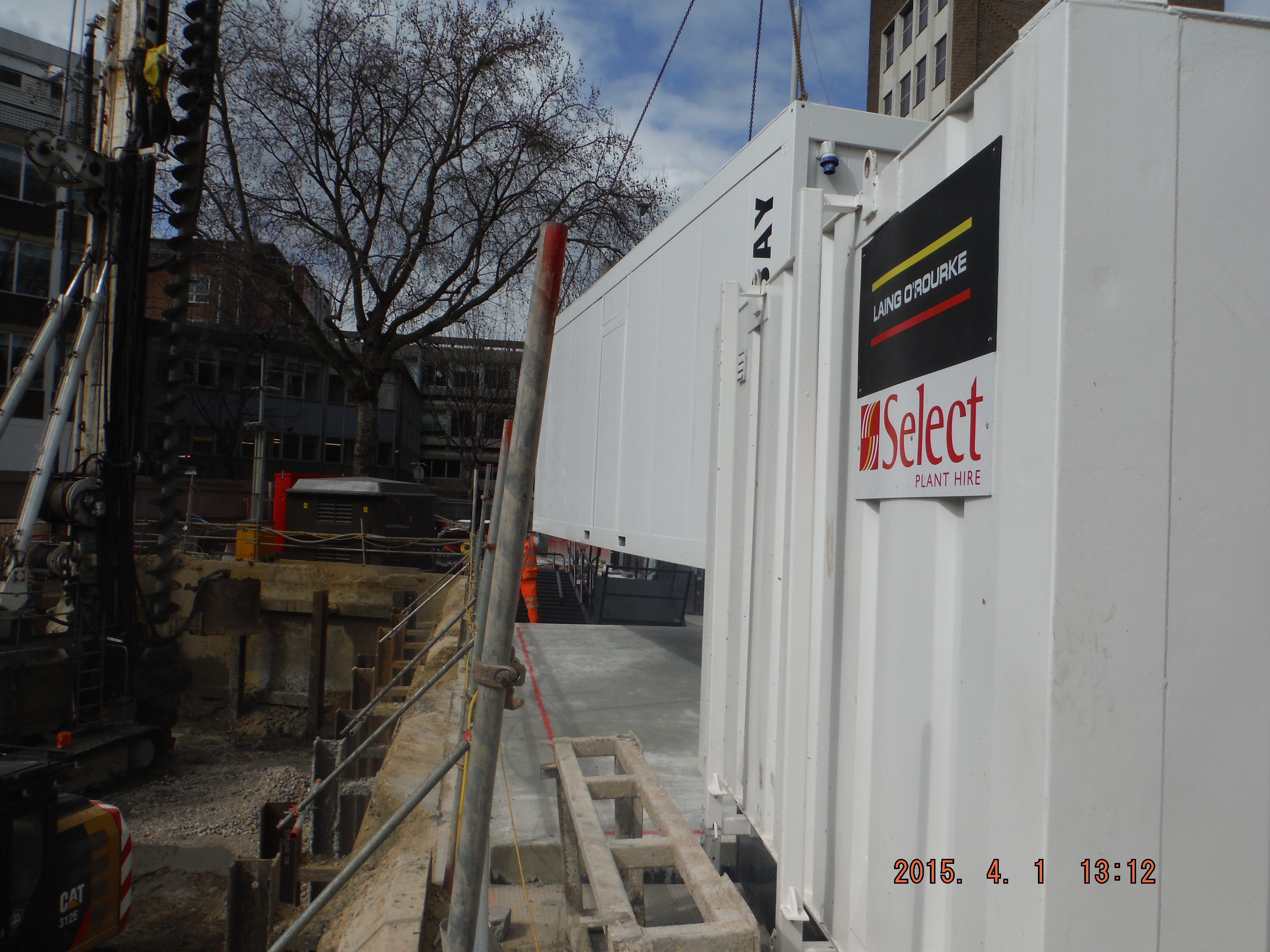
Welfare cabins arrive.
Excavator sitting on pile mattress where future sheet piling will take place.
Progress. We are currently about 3 weeks behind schedule, mostly due to pile rig breakdowns, a few unforeseen ground conditions and a bit of a few things just taking longer than planned.
Foreseeable practical issues.
1. Sheet Piling – I can see that preparation for the sheet piling is going to be difficult – we have potentially struck a fibre optic cable (green pipe sheath below) and there are many other cables which led into the old substation. How to resolve – careful hand digging and attempting to recognise if cables were part of the old substation or not. How to resolve cutting a fibre optic cable – I am holding my breath.
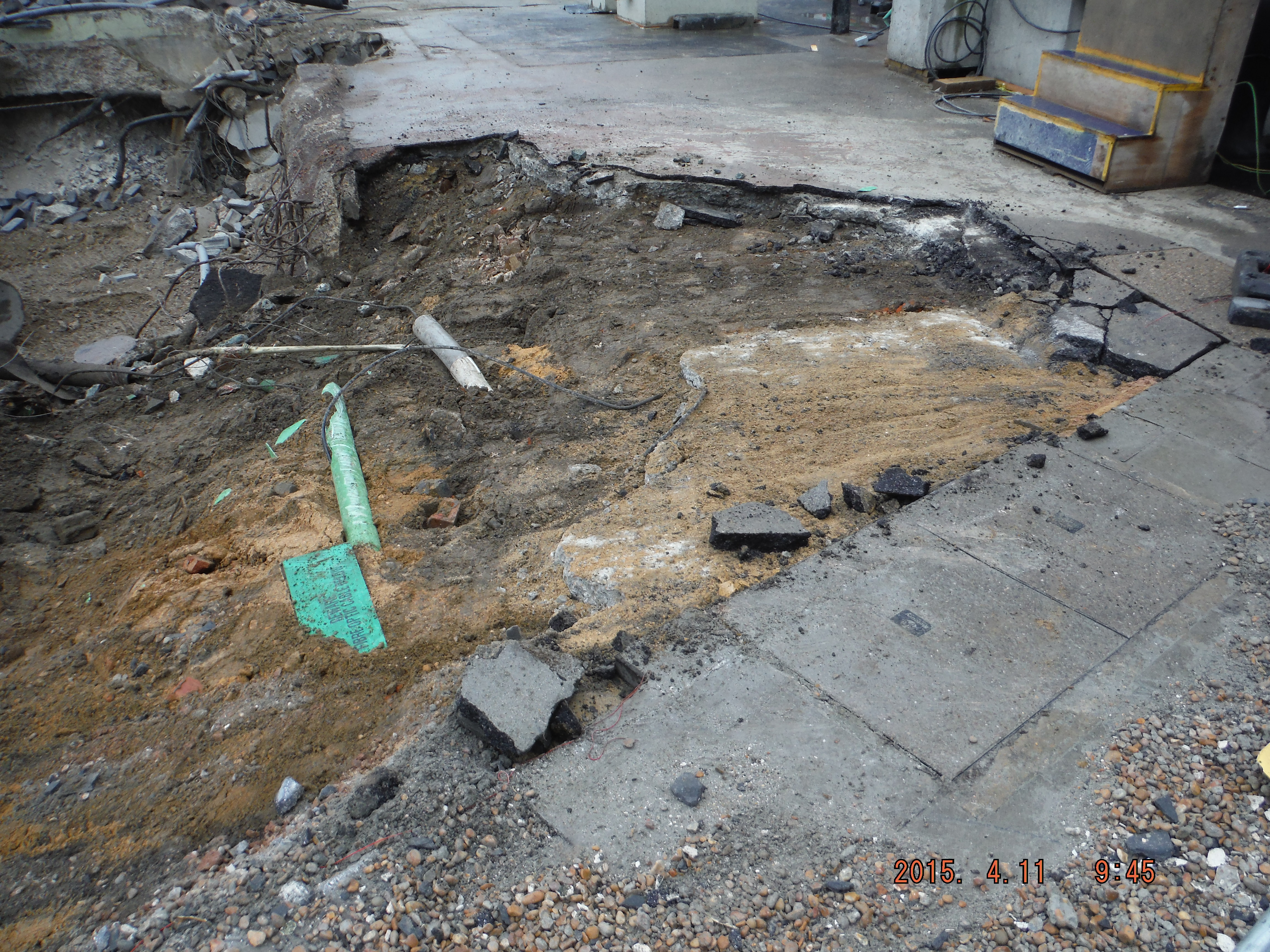
Fibre optic cable strike? If the IT companies all arrive on site on Monday, I have a problem.
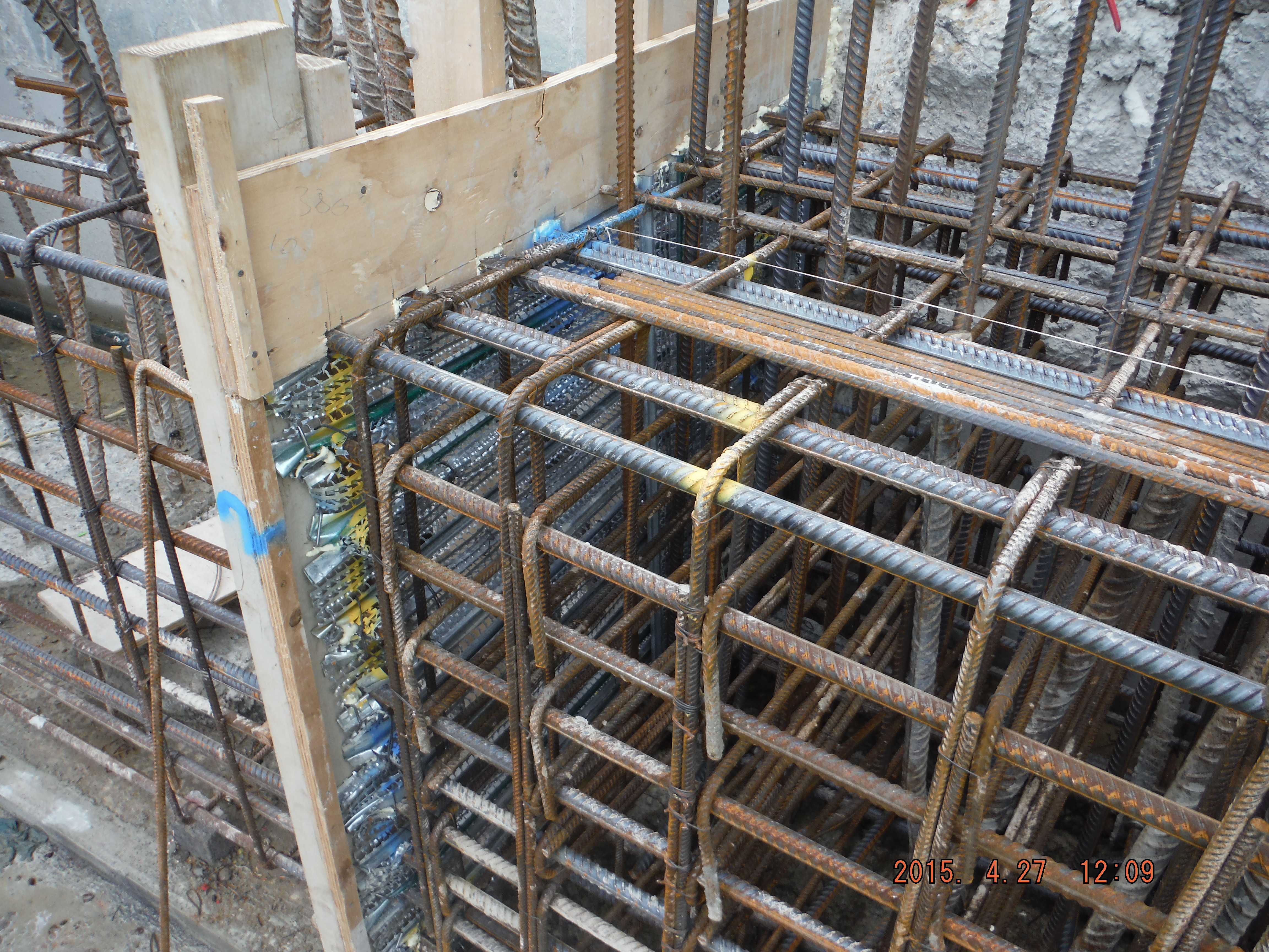
2. Capping beam – as you can see there are male pile tops to cut, king post (vertical steel columns) and a complicated as you like “shear stub” connection (Richard – this may ring bells from my questions away-back in December) for the ground force props to enable excavation of one further level. This is surmountable but is going to be painstaking threading re-bar through the stub as well as lifting them about (each way in excess of 200kg).
3. Ground water – the ground water level is about at bottom of blinding of the capping beam. We cannot drain the bath that is the entire site because the secant wall is not finished. Current method of resolution: Effectively at the moment we pump water out for it to recharge into the hole, albeit giving us long enough to work for the day. Should it rain heavily for days there will be a problem.
Other points:
ICE webinar brief on CDM 15 on Monday for those interested!
Another cyclist was killed by a construction vehicle in London this week. Laing O’Rourke are a Construction Logistics and Cyclist Safety (CLOCS) Champion but do all vehicles that deliver to site comply with the minimum safety requirements… to be continued!
Site Two Fifty One – Uncertainty in Ground Conditions
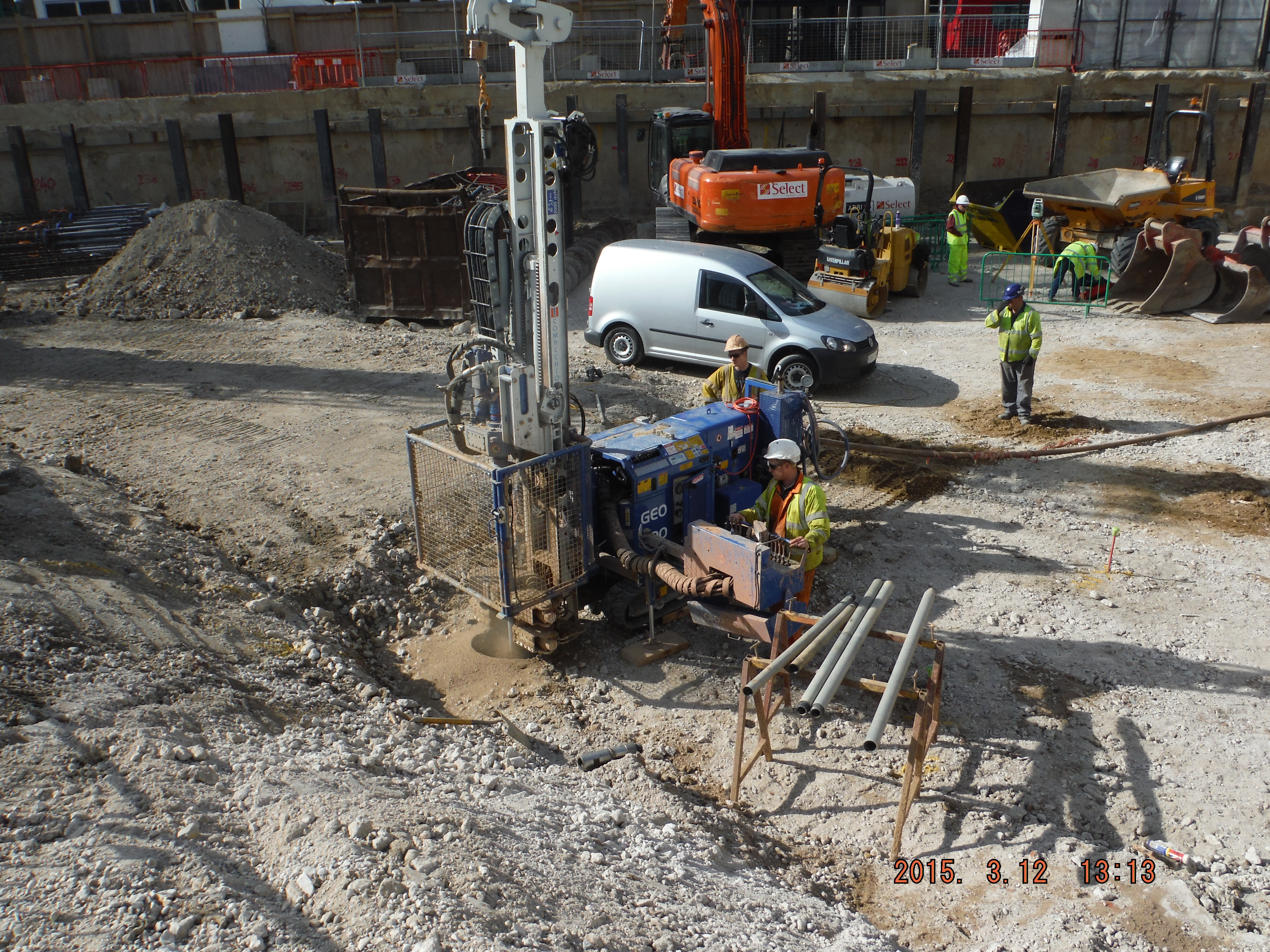
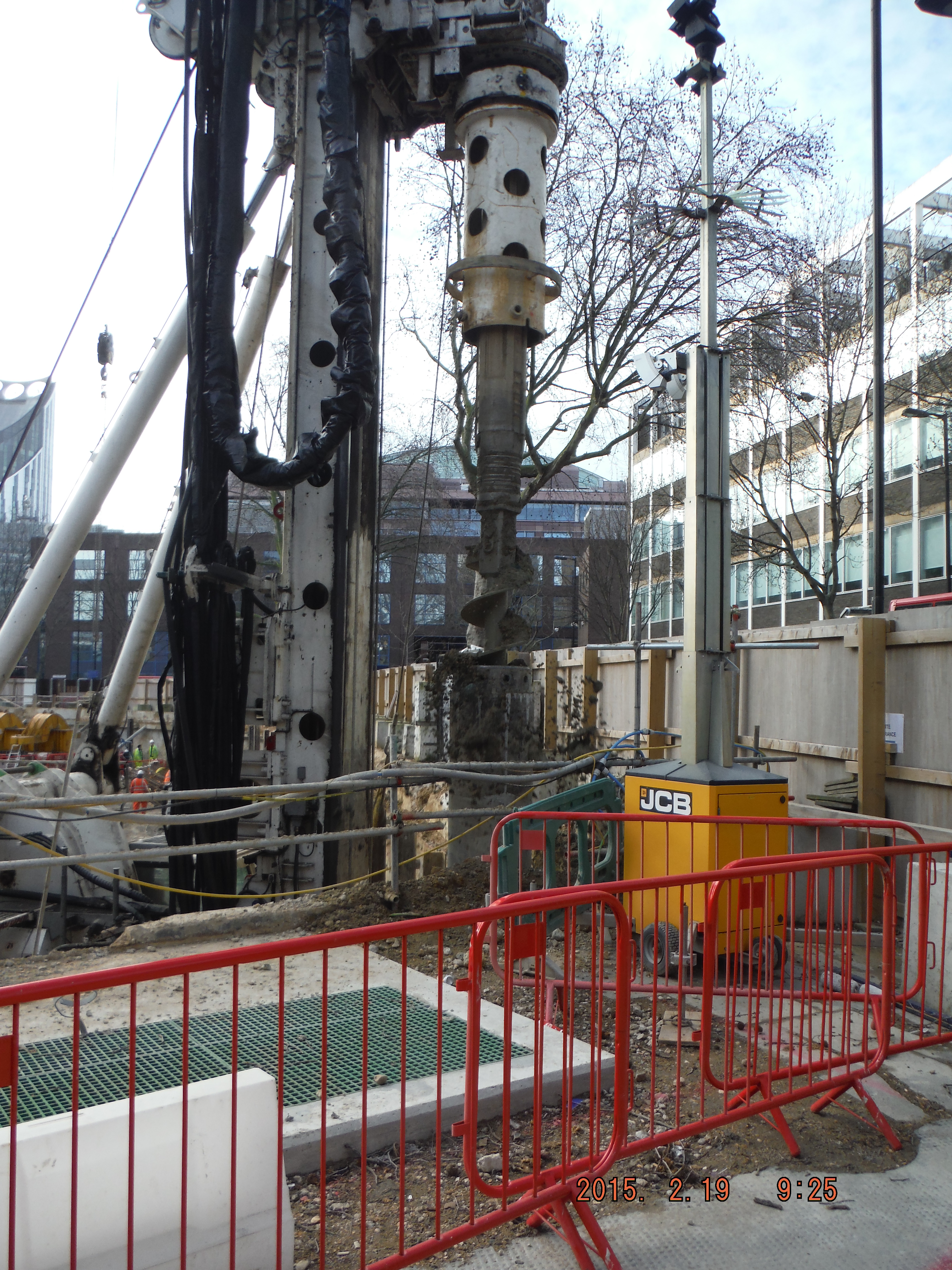
On Wednesday, the first ground bearing CFA pile was drilled. The stratum is made of 7m of river terrace deposits (sand and gravel) then 19m of London Clay. The auger was drilled to a depth of 24m and on extraction the nozzle at the base of the auger was found to have been blocked (reasons are extensive – poorly primed hoses, gravel getting stuck within the bottom of the auger, but not the focus of attention here).
On removal of the auger the gravel began to “flight” which is where the size of the hole increases in relation to the bore diameter. This is a particularly prevalent problem in sands and gravels. Add in a water table at about 1m depth and that compounds the problem.
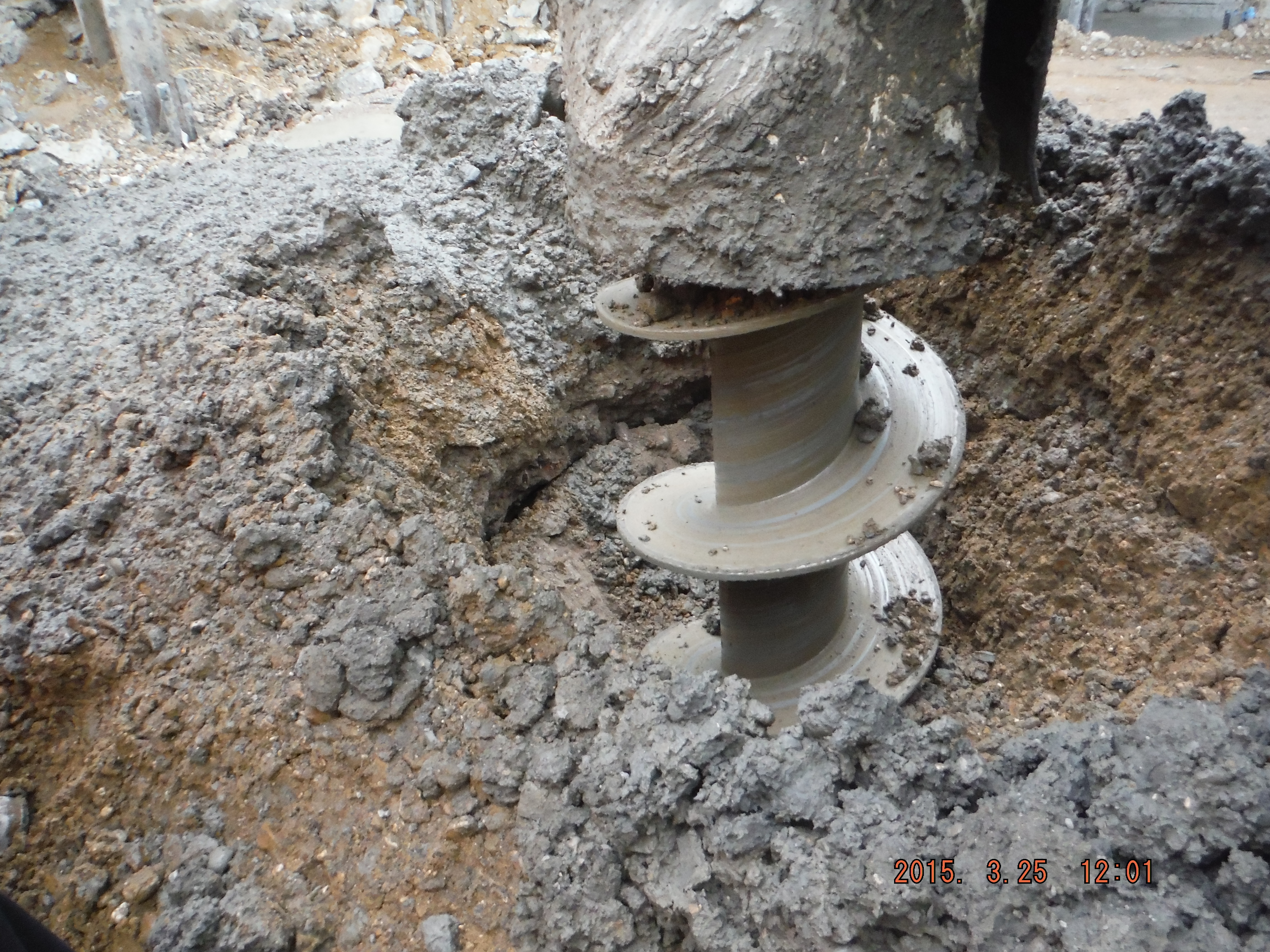
Pile diameter much greater than auger diameter
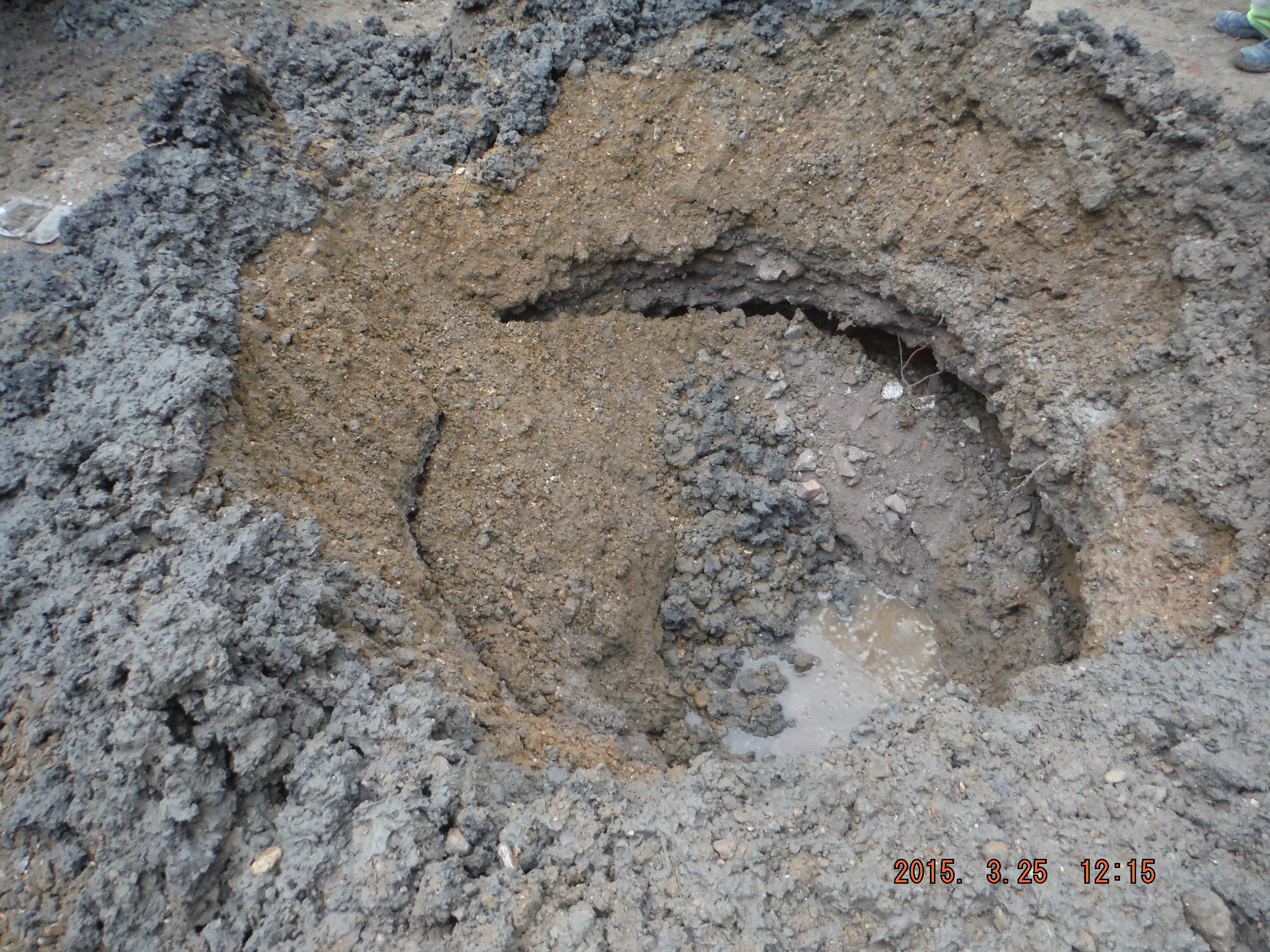
Pleasingly my pile mattress was doing a good job at holding the pile rig up. Less pleasingly was the undermining occurring below it potentially causing diffemderential settlement and risk of the rig turning over.
Hole diameter increased 4 times original.
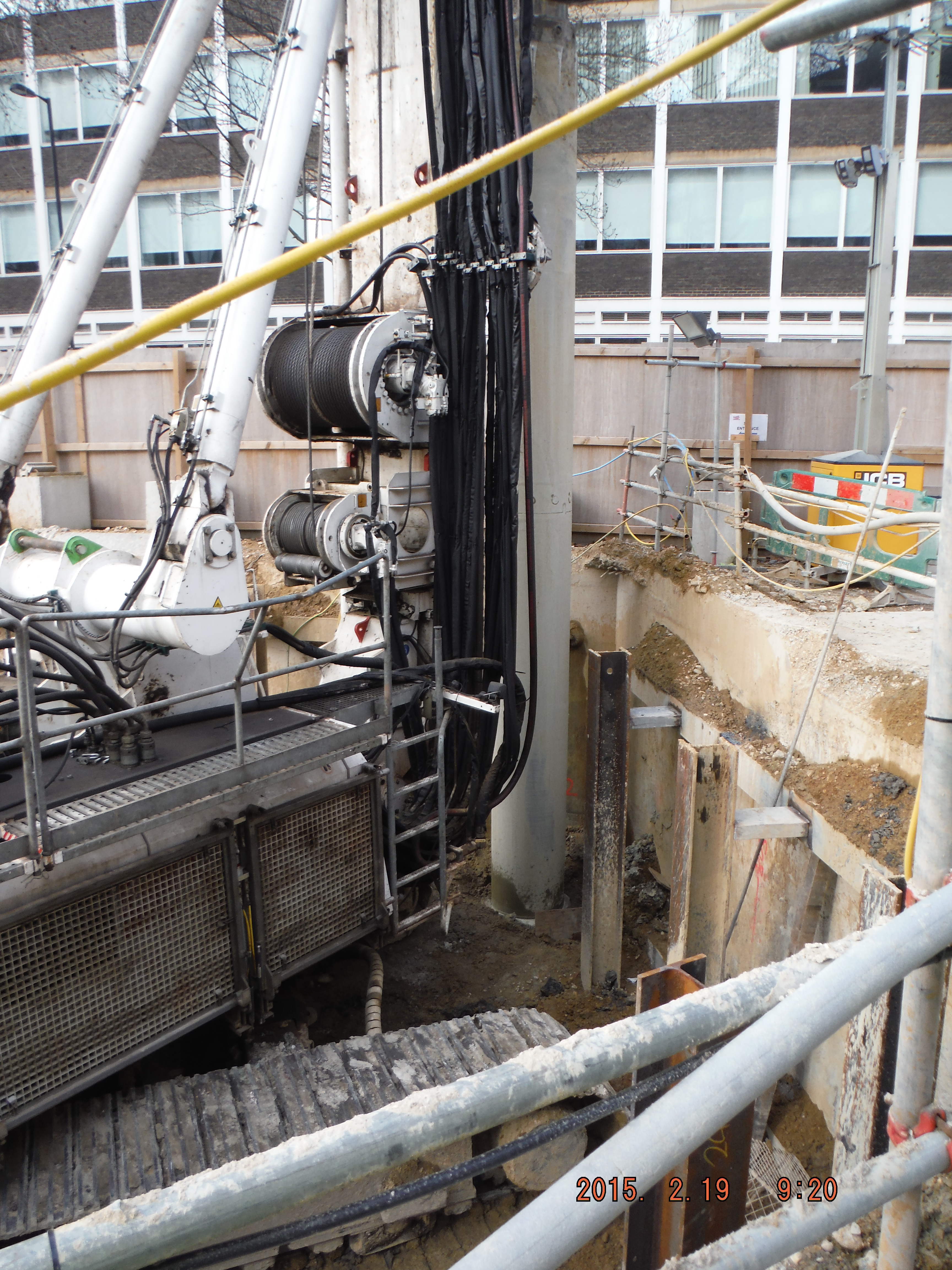
Take 2. The next ground bearing pile was approached in the same way. Auger goes in, no blockage, concrete comes out and auger extracted. Nice vertical concrete pile. Then the reinforcement cage was added then it was pushed into the pile with an 8.5m column to sit the cage at the right cut-off level. This was in order to avoid breaking down the pile with reinforcement in. Everything great.
Pile rig mast toe not being undermined.
Reinforcement cage being lowered into pile hole 750mm diameter
Cage plunged firstly with excavator bucket
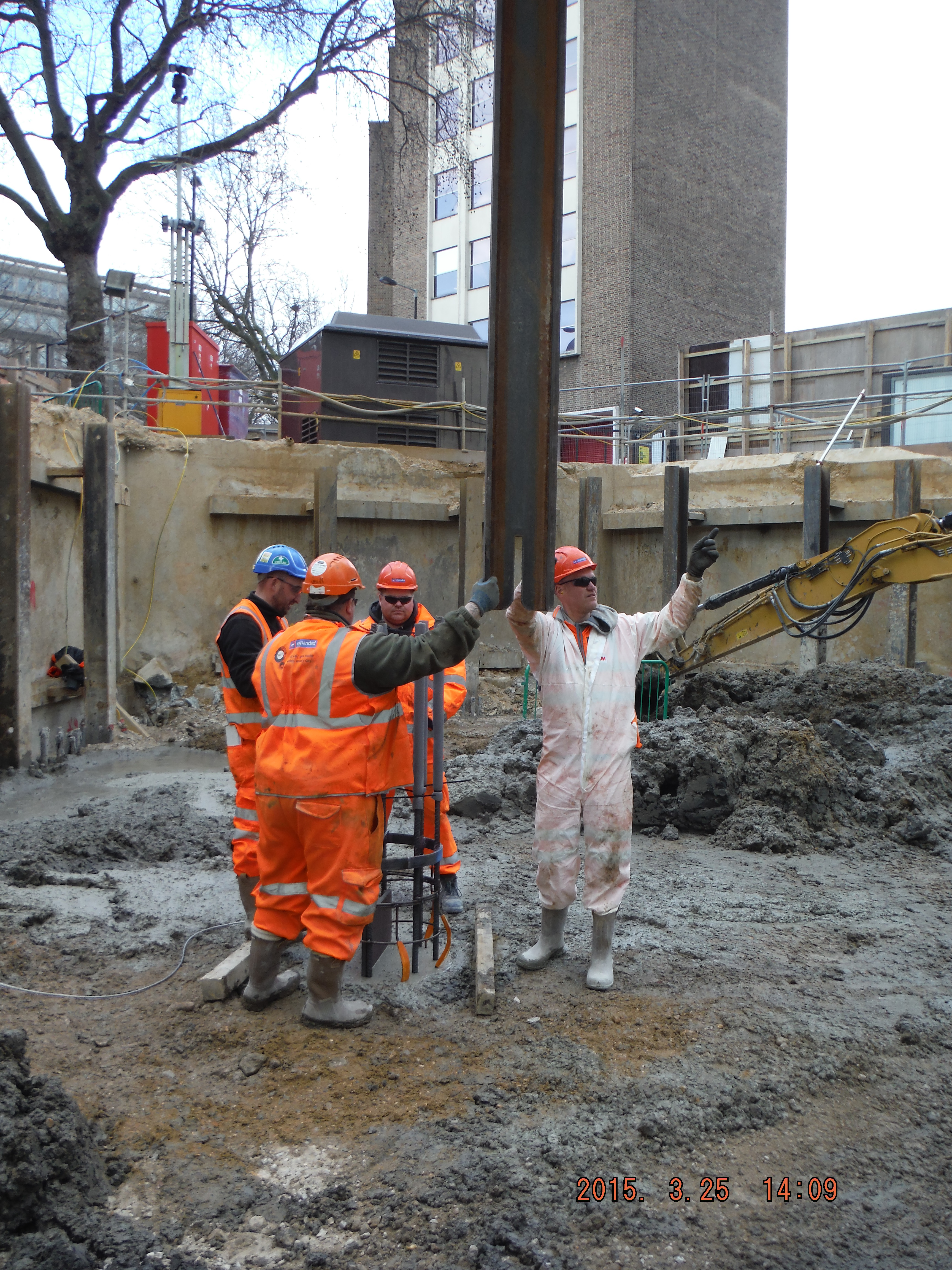
Cage plunged secondly with an 8.5m RSJ

Steel wire rope used to stop the reinforcement cage from embedding any further into the pile.
Take 3. Auger is drilled in and at about 20m embedment the extracted material from the pile drops into the ground. The foot at the bottom of the pile rig mast was starting to get undermined and so the drilling was stopped and the auger retrieved.
With John Moran’s prompting, he directed me to the ICE Specification for Piling. There is a section on CFA piling in ground with a loose section overlaying a stiff clay layer – see below in Option 1.
Solutions
Option 1.
Reduce the auger rotation in relation to penetration. I.e. reduce the auger turning speed or increase the rate of penetration. There must be some flighting (or extraction of material) to avoid corkscrewing the auger into the ground which would then be impossible to retrieve.
The specification says where there is high ground water there is higher risk of over fighting and so casing the piles should be considered.
Option 2.
We have just reconfigured the pile rig from cased rotary bored to CFA because it enables the deeper piles to be installed in the Lambeth Group below the London clay. So changing back to Cased is not likely to happen. Additionally the combined case and CFA rig that Laing O’Rourke own only drills to 17m.
Option 3 – chosen option.
Surcharge the loose ground around the auger with dry material. This should then stop any displacement of material around the pile mast. Turns out this is pretty effective! 4 piles done on Thursday and 4 on Friday.
Why does this work? I will attempt to speak in effective stress language. I think this is nothing more than a case of the quick condition, recently spoken about by Guz. As the auger penetrates through the Gravel it unloads the ground (simply by extraction of material by the auger). With the high water table, and the reduction in total stress, the augering results in the effective stress (Terzaghi : σ’ = σ – u) reducing to zero, i.e. piping. Hence, this causes the ground around the hole to fall inwards. So by adding additional total stress (surcharge) it maintains a positive effective stress and stops the ground from collapsing. So now piling can continue.
Technology merging with health and safety.
Site Two Fifty One
Technology merging with health and safety.
This week I attended the Laing O’Rourke “Mission Zero – Ask the Question” workshop. This is the Laing O’Rourke mandatory health and safety briefing which aims to get their staff to work safely on projects. It is a pretty decent attempt at raising awareness of health and safety in the workplace and potential pitfalls when working on projects. Impressively, Laing O’Rourke has produced a short film illustrating an accident on one of their sites (early removal of back-propping causing a slab collapse). The film is relevant and applicable to many sites, raising multiple issues and creates an excellent scenario for discussion. The real focus of the workshop was not to teach employees about health and safety, but simply get people asking the question to ensure activities are done safely.
Later in the week I attended Priority 1 training. Perhaps familiar to some, but likely not all, this is an online tool to enable snagging, permits, tasks and observations to be recorded electronically and geographically. The software aims to “improve the way that information is collected, managed and reported within live construction projects”. The example I will cite is based on the Health, Safety and Environment Supervisors’ check I do weekly. One of the items I check is edge protection. If I find a missing toe board, I then raise an action. I take a photo, fill out a short form and assign a date and organisation to resolve the problem. You might say what is wrong with a paper form and telling the site foreman to sort it. That method works but it fails to record trends and give the project leader timely feedback on issues that have arisen. Moreover, the snagging tool allows tasks to be assigned to a variety of sub-contractors which can then be monitored for their progress and have records kept with the photograph/location data acting as evidence of performance. It’s a good tool and probably has lots of other useful functions which I expect will become apparent soon (issuing of permits for example).
This week, a PowerPoint brief was issued for delivery on-site to highlight recent issues across multiple Laing O’Rourke sites. Good information sharing and method of learning from others’ mistakes. Especially applicable as we do all of these activities!
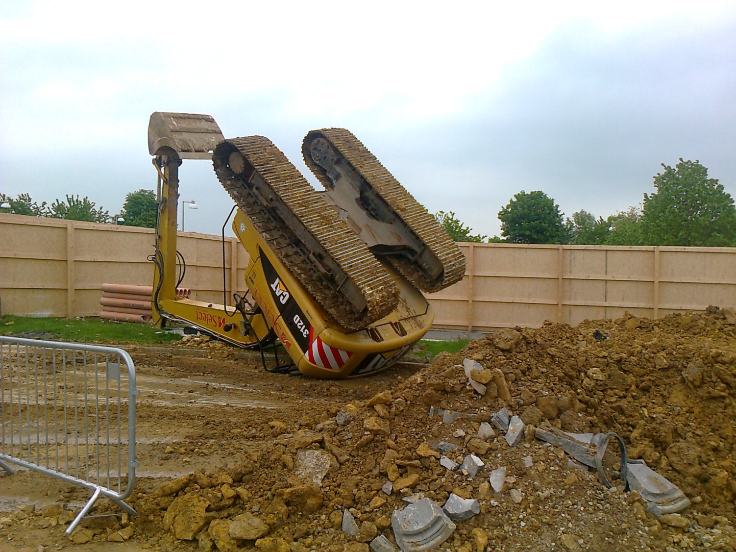
Excavator overturned when loose item in cab became trapped under operators pedal.
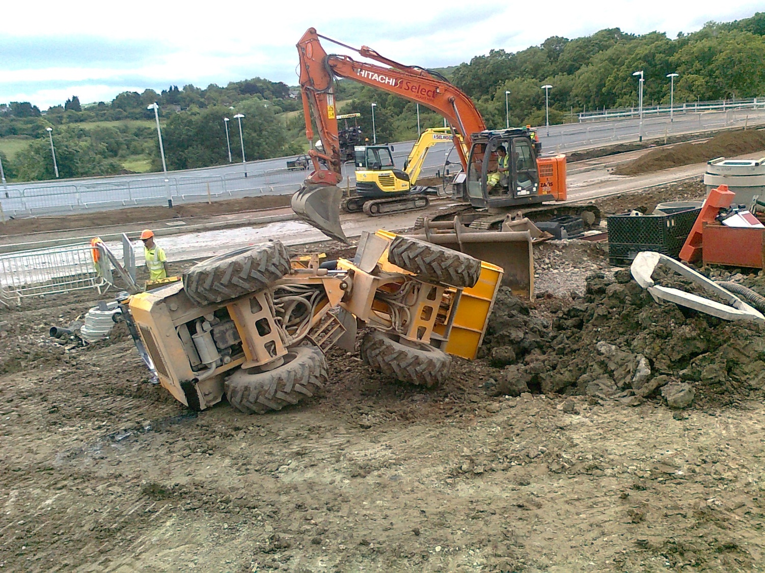
Mini dumper overturned when bucket was elevated whilst machine was positioned on incline
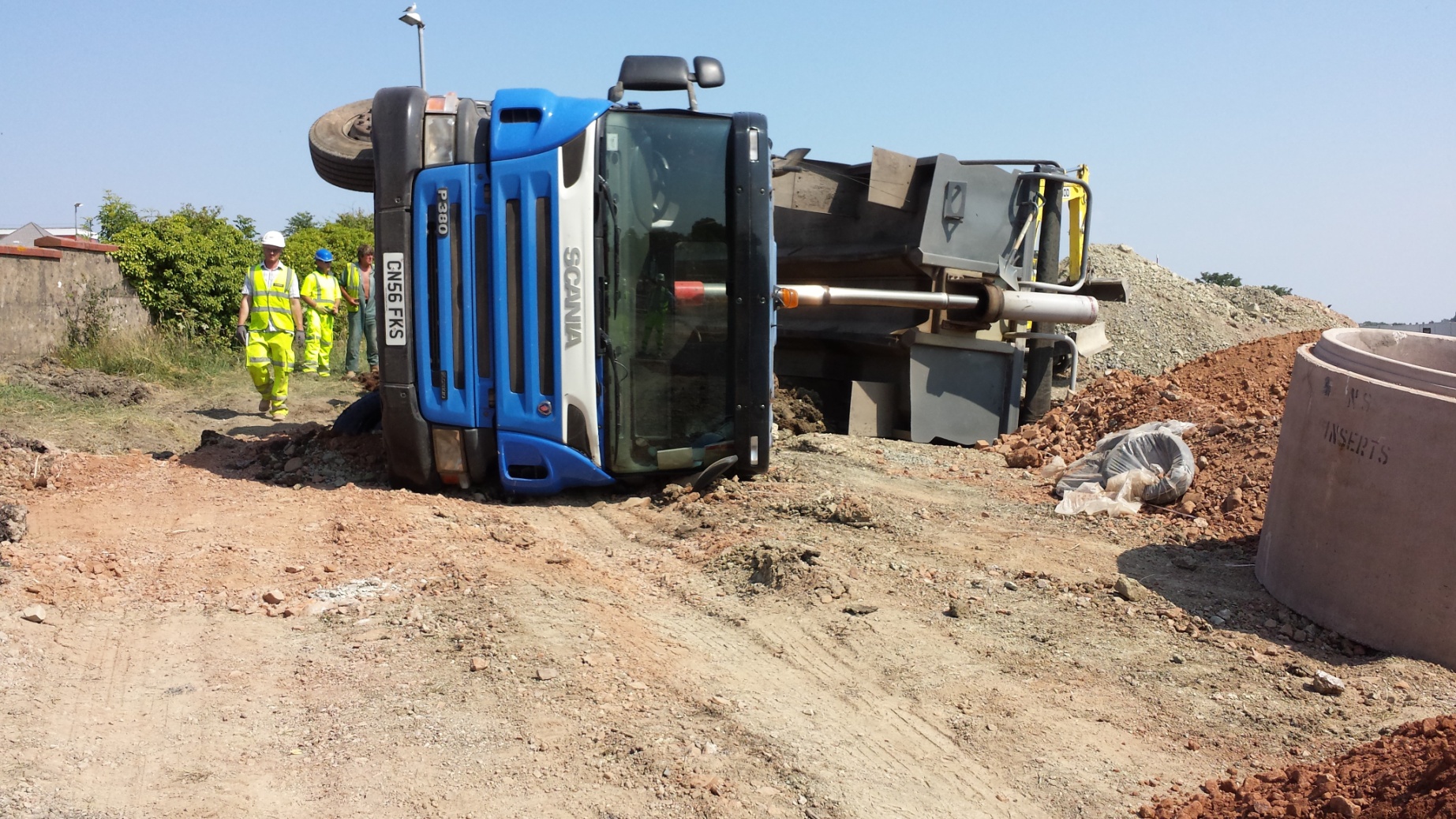
Tipper wagon overturned due to unsuitable ground conditions – wagon should not have gone onto area in question.

The area being rolled was sloping to the left. This should have been levelled out prior to and during the backfilling operation.
Military – Civilian Processes
I thought I would look at a few checks/processes in the world of construction I think the military do well at based on my experience of the civil industry. The people/checks/processes are all present/done on civilian construction sites and it really has reinforced the good old Troop Commanders’ checks being vital to keep a project running. Not just with counting spanners but the checks to ensure the equipment is serviceable (PA test in date and item functions).
QM in charge of materials and logistics
SQMS to make the logistical chain
G1098 storeman
Lifting tackle register
Tp Comd monthly checks
Equipment Care Inspections
Complete tool boxes for tradesmen
SHEF statements
Section composition (section comd and 2ic with tradesmen)
First parade checks
Whole Fleet Management
Risk registers
Fire NCOs
Tool box talks
Orders process
My site is at an early stage and so effectively lacks a bit of section comd leadership. It has some good quality tradesmen but a lack leadership skills are to be found on-site. I know on more advanced projects lots of these things (G4, material requisition, health and safety provision) just happen but in my case, I (we) are establishing the safe systems of work. I would like to say it is a bit of a pain, but actually I am learning a lot from it and think I will learn more from a maturing system, rather than a mature system.
Condors, Piling Methods and Bomb Hunting
Site Two Fifty One
I’ll reflect on 3 points this week.
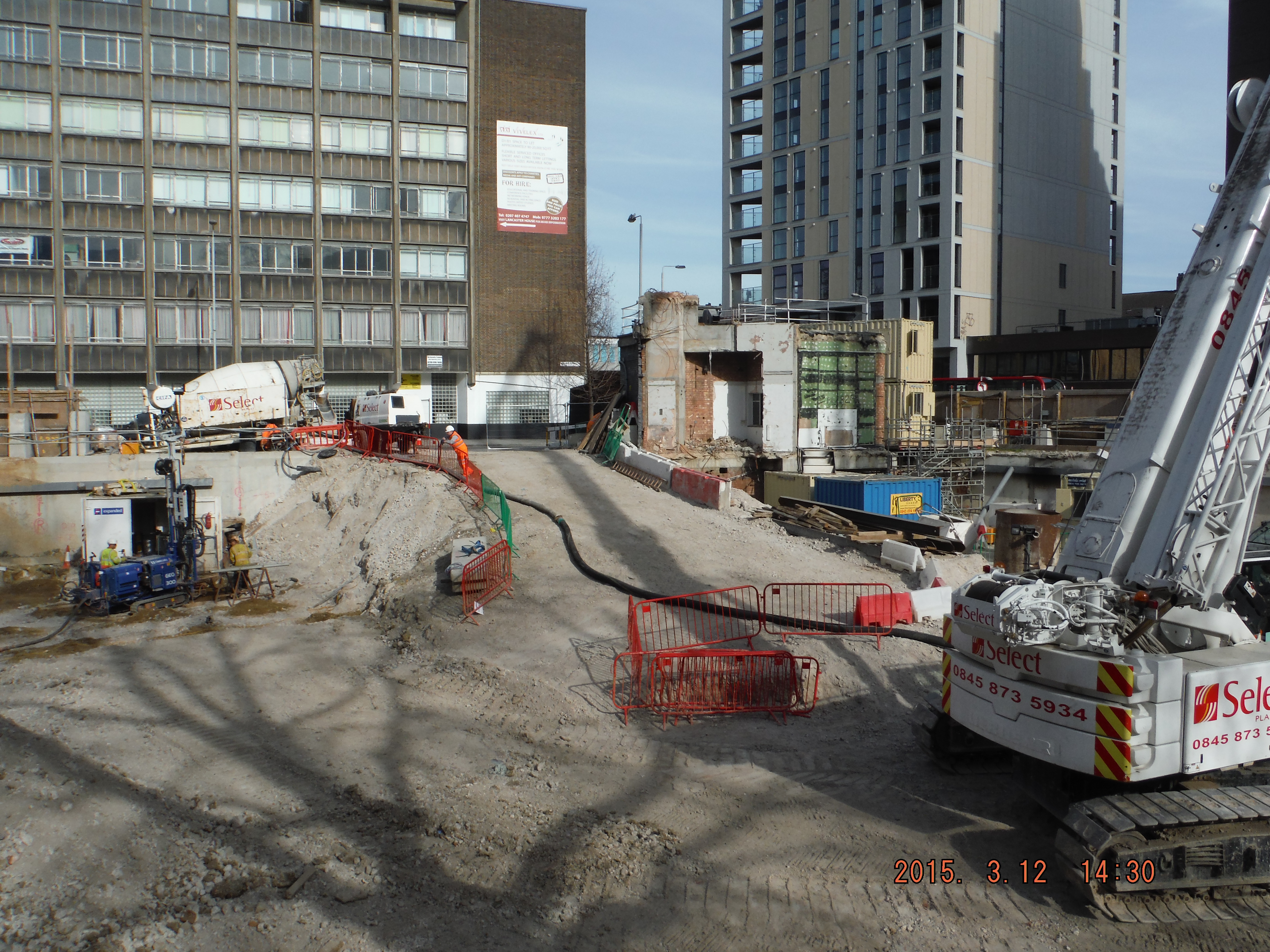
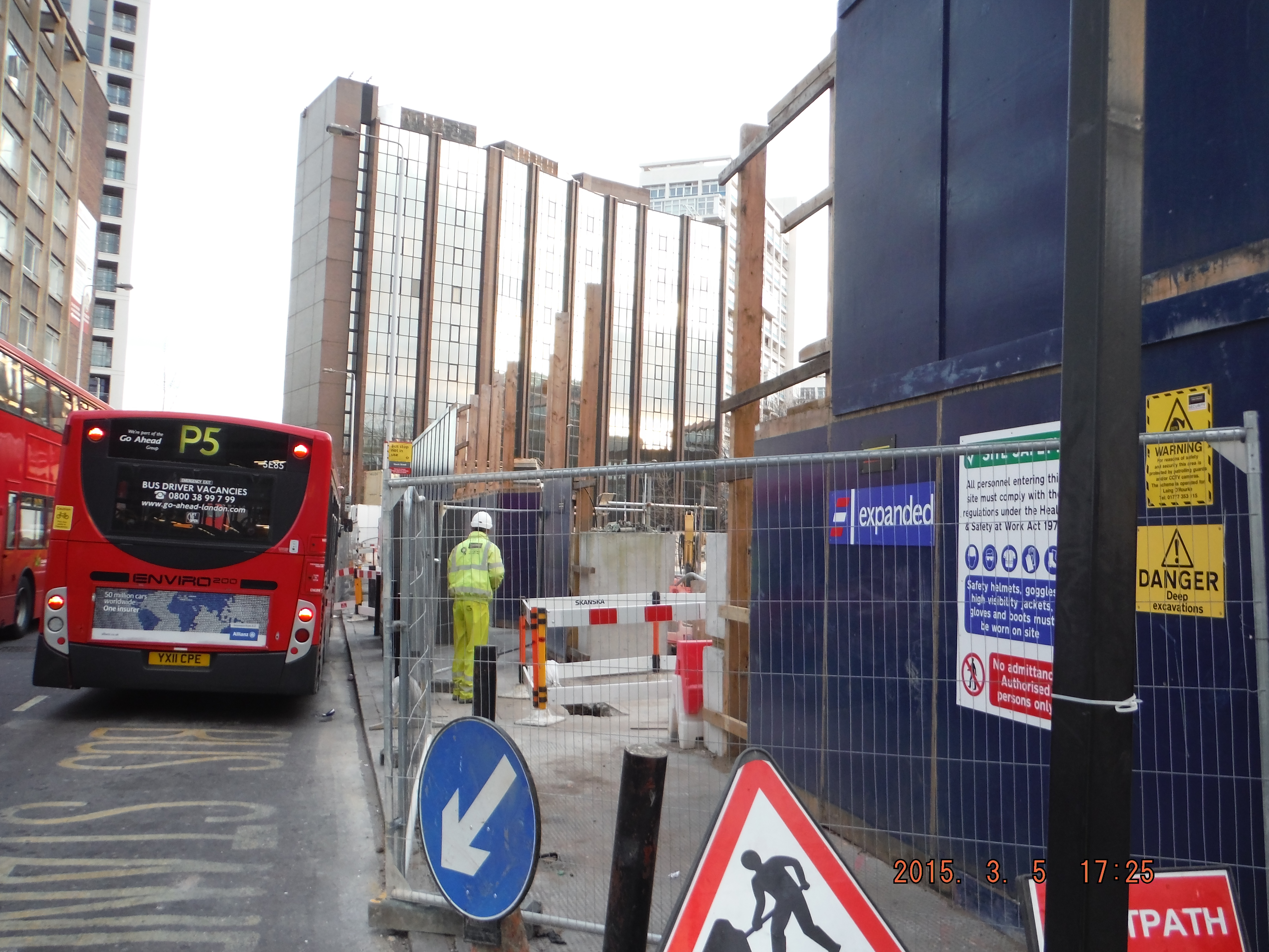
1. Sensible Health and Safety. This week’s Monday morning was more “Monday morning” like than any other – the busiest day on and around site to date. PM on leave and Project Engineer arrives at 9.30am (site works start at 0800). Typically muck away lorries, UXO survey team, slab breaking, pile rig conversion (rotary to CFA), perimeter hoarding move, substation re-routing and traffic management all collided at once. Add in the client’s representative visiting and an already confined and cluttered space and you have issues. Unfortunately the UXO survey team arrived late, muck away trucks got stuck and converting a pile rig needs loads and loads of space. This inevitably started to cause chaos and not just the site was becoming unmanageable, the roads around the site perimeter were getting blocked. This was the time to take the condor moment: step back, think and act. I chose not to and felt the client’s representative needed to be briefed. I missed the increasing hazards and did not take control. Shortly arrived the Project Engineer arrived he stopped the works (not for long because it just needed a few composed minutes to sort things out), cancelled further muck away, and installed new walkways to make safe passages between work areas. Simple stuff and a big lesson learned for me to then reapply the following day when the situation changed again.
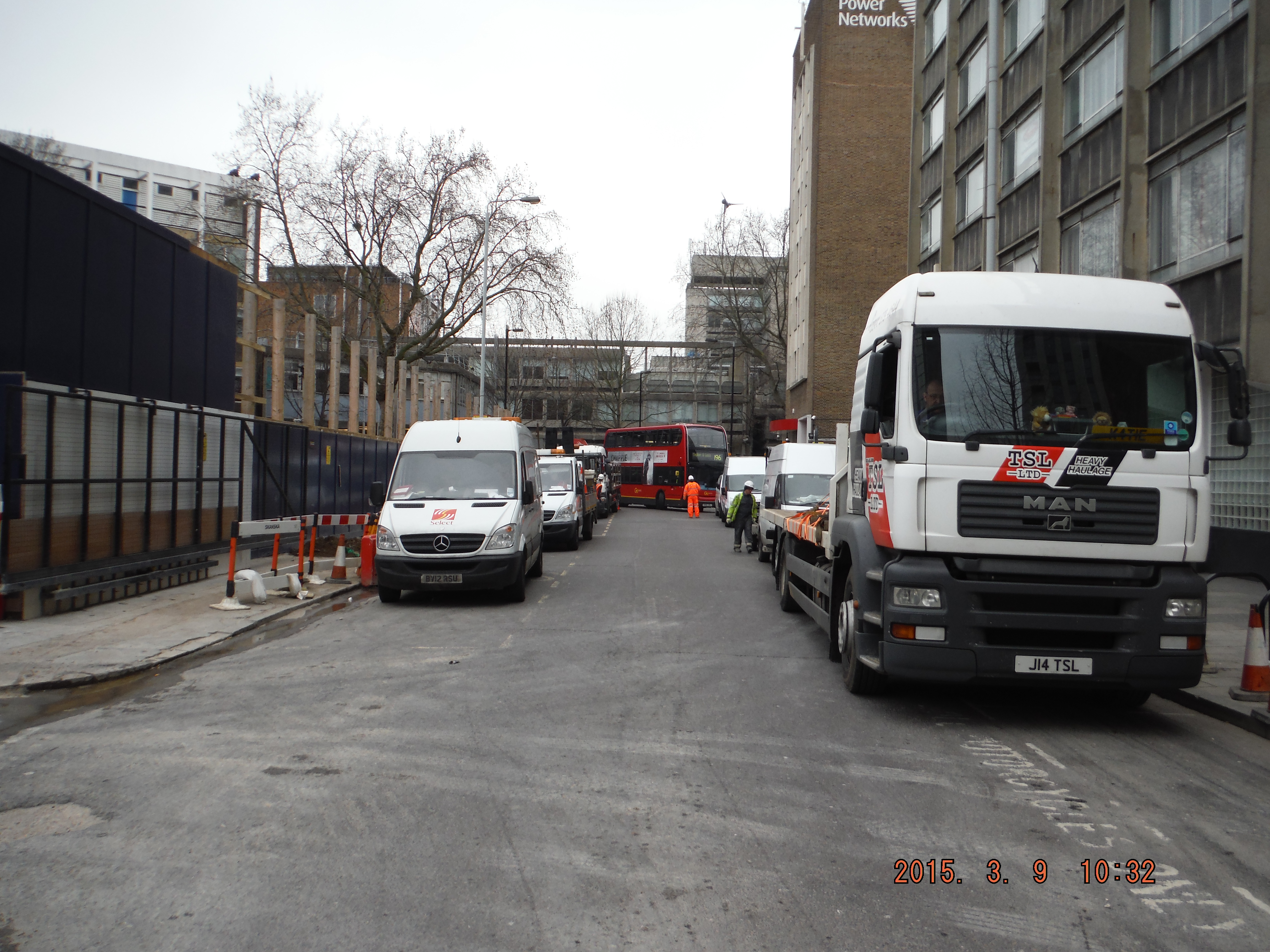
Site perimeter, Gaunt Street, choked with site vehicles. See high-ab arm at the back and the London bus attempting to get through.
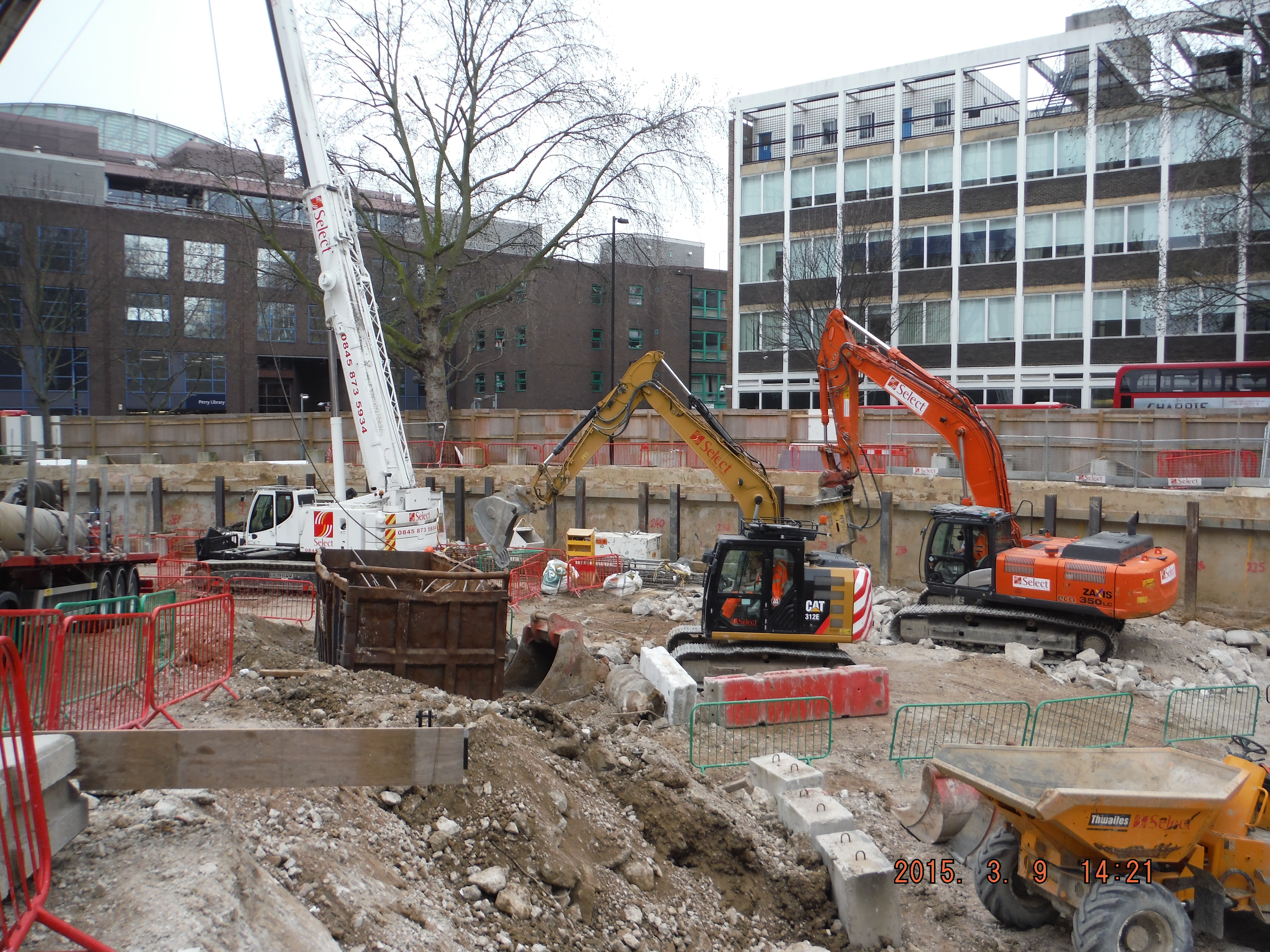
Site in overflow: slab breaking, excavation, skip exchange, deliveries, piling and UXO.
2. Pile type, Rotary to CFA. Some reminders for me/anyone who is doing either type of piling in the future. Firstly, allow 3-4 days, not 1 or 2.
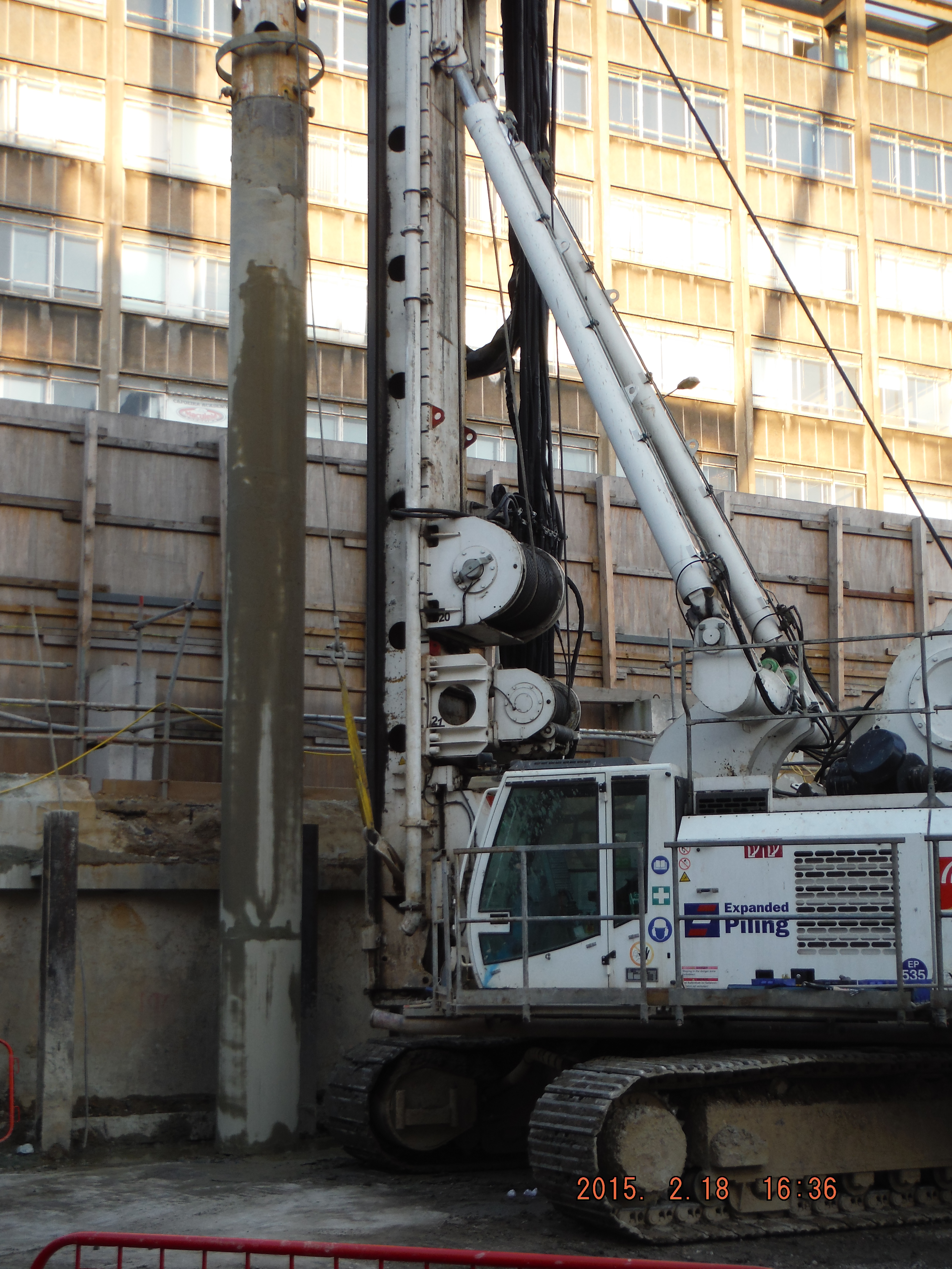
Rotary bored (replacement). This is where the casing is bored into ground and a rotating auger is used to excavate the soil within. Casing keeps the hole open and makes a pretty neat pile. This method struggles to work at 38m depth and in dense sand – hence the change to CFA.
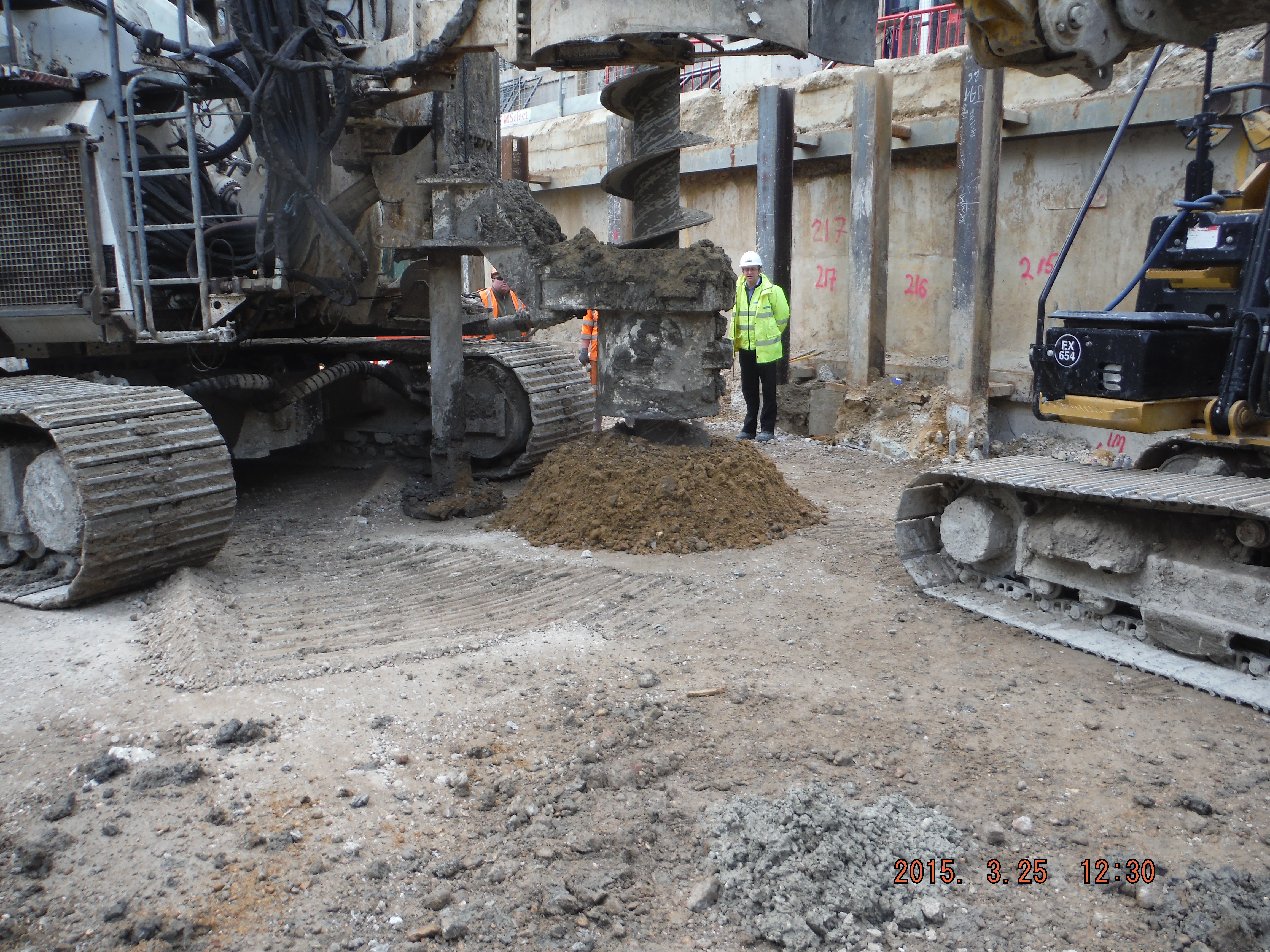
CFA. The first key point is that the space it needs is huge. Not just the longest drill bit you will have ever seen (it comes in 4 m lengths) but the guard which removes spoil from the auger means more space around it is needed. Additionally rather than just having a pile rig, crane (to lift reinforcement), and concrete wagons, you also need a pump which needs 3m of extension hoses, a thick hose line and an agitator (stationary concrete wagon) to mitigate typically infrequent concrete deliveries in London. Add this to the above Monday morning scenario and unless the situation is well planned you have problems. The first pile was constructed and the volume of concrete was horribly out requiring the pile to be drilled out and re-poured. Why – probably because the massive drill bit auger, without a casing, had brought in material from the edge of the hole making the hole much bigger. So what, well for a start, it is very difficult to predict the concrete quantity, secondly it makes for a very uneven pile and thirdly who pays for the extra concrete (about 30% extra than the cylindrical volume budgeted only, about 50% extra required)…
Crane moving reinforcement ready to be inserted into male pile.
Alternative CFA concrete delivery – direct to pump without agitator.
Auger guard hits back wall, solution – remove top of back wall!
CFA – 30m auger
Expanse of CFA plant. Left: agitator (static concrete wagon), pump, hose, crane, (out of shot) pile rig.
UXO Survey. Some photographs of the magnetrometry in action (magnetometry or electromagnetic surveys are used in the search for buried UXO and rely on the detection of small variations in the Earth’s magnetic field caused by the presence of ferro-magnetic objects). The UXO survey was required as a result of a study of WWII maps highlighting a medium risk of UXO within a certain area within the site. Risk mitigation or contract covering exercise…
UXO probing: Drill, probe, analyse.
Note the compressed air causing the ground water to bubble in the previously dug holes (up to 9m away out of shot)
It’s a hole new world out there.
Site Two Fifty One
The aim of this blog is twofold. One – highlight what I am doing and learning on site, and two, discuss unforeseen ground conditions.
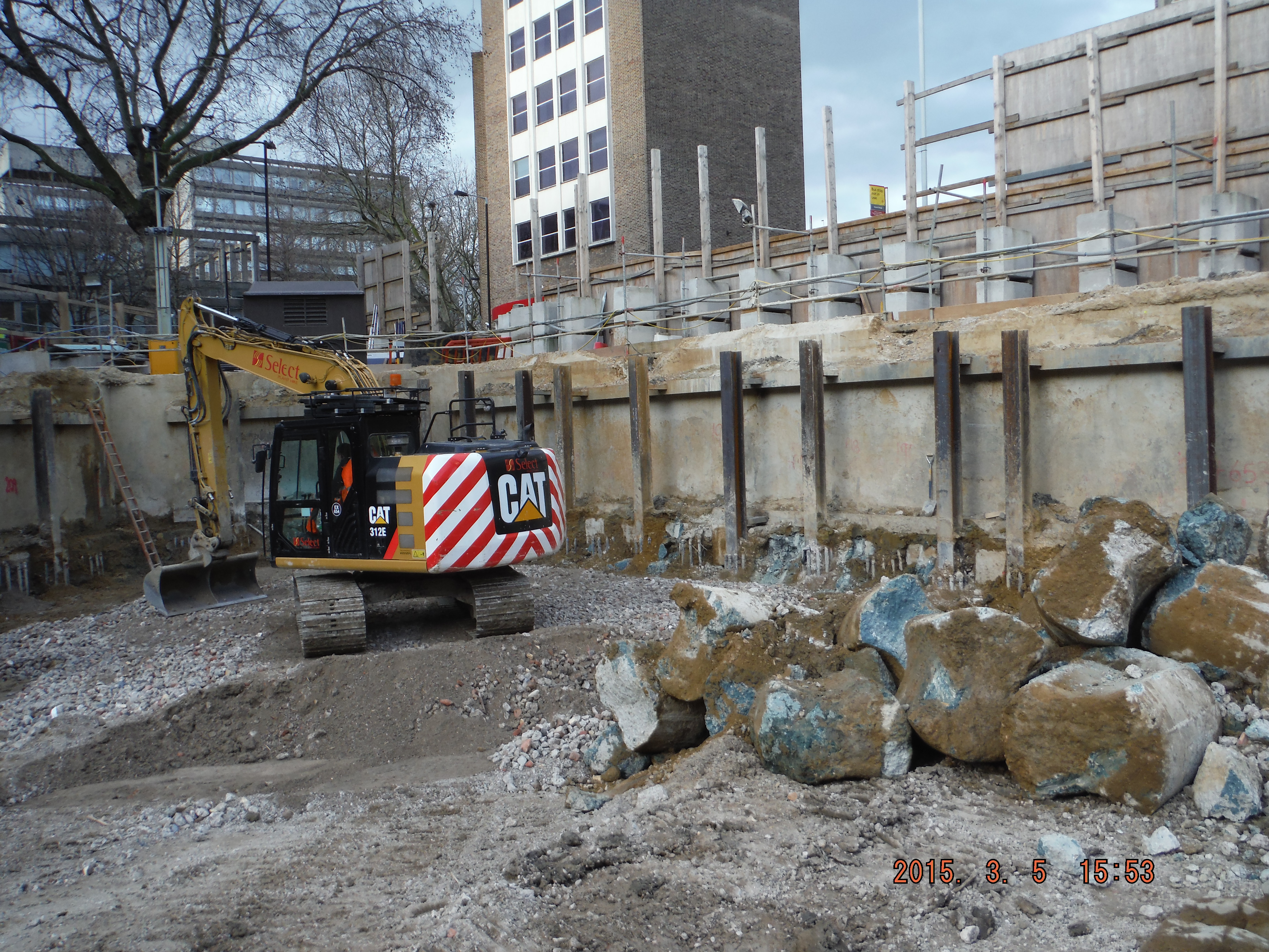
I arrived on site on 16 Feb and since then the focus has been on constructing the secant pile wall. The pre-existing site had one level of basement with an 800mm slab acting as the bottom prop. The slab is being used as the edge of the guidewall for the secant pile wall construction. The male piles, installed at the first basement level, extend to 26m depth through 6m of river terrace deposits and then into London Clay acting as an impervious cut off. The secant wall will act as a cantilever retaining wall when excavation to basement level 2 commences.
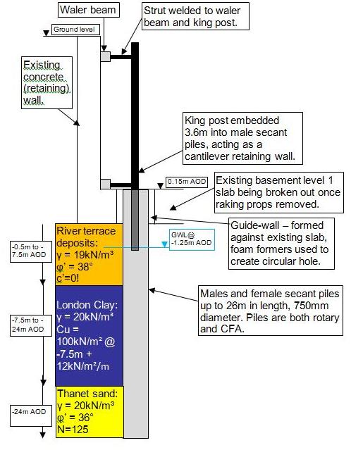
Cross section of secant pile wall, king post propped cantilever and ground model
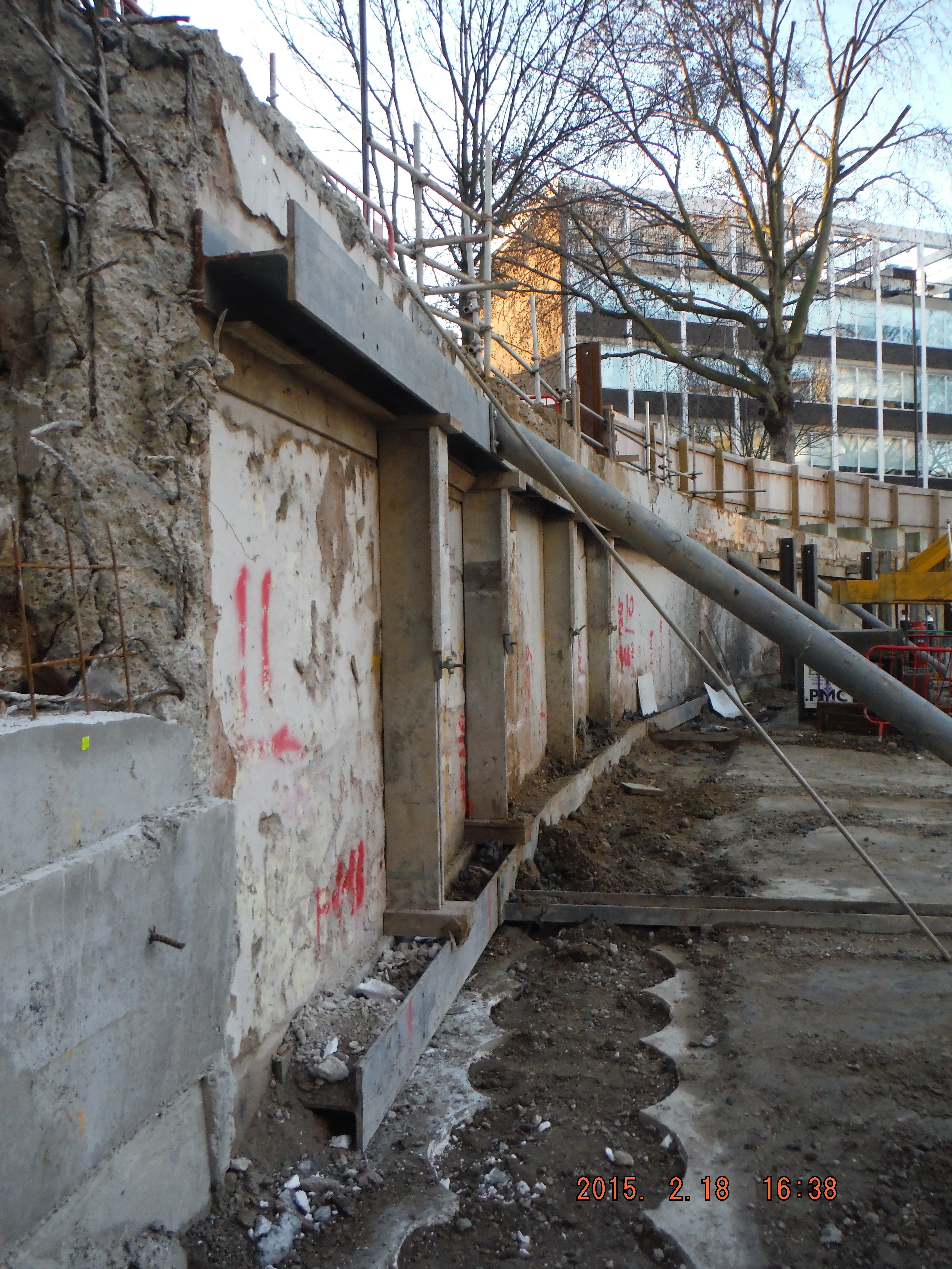
1. Pile Guide Wall (near ground) 2. Raking props to existing slab provide lateral restraint to existing wall (middle ground) 3. King Posts protruding from males secant piles to support existing wall (far ground)
Piling. My role has being to coordinate the piling team to install the piles, specifically where to put king post columns to prop the existing wall up. This just requires thinking about which male and females piles to do to avoid doing them too close to each other and keep the pile rig put of the way of temporary props. Easy in open straight sections, a massive pain in the corners of the site.
Site management. The project is at an early stage so welfare and office facilities are limited. The perimeter hoarding needs to be moved outwards and the live substation needs to be decommissioned after we have set-up a temporary one. Dealing with UK Power Networks and Skanska has been a challenge and I am now very aware of how to excavate around live services (Skanska operatives, however, seem less keen on digging by hand when within 500mm of services…)
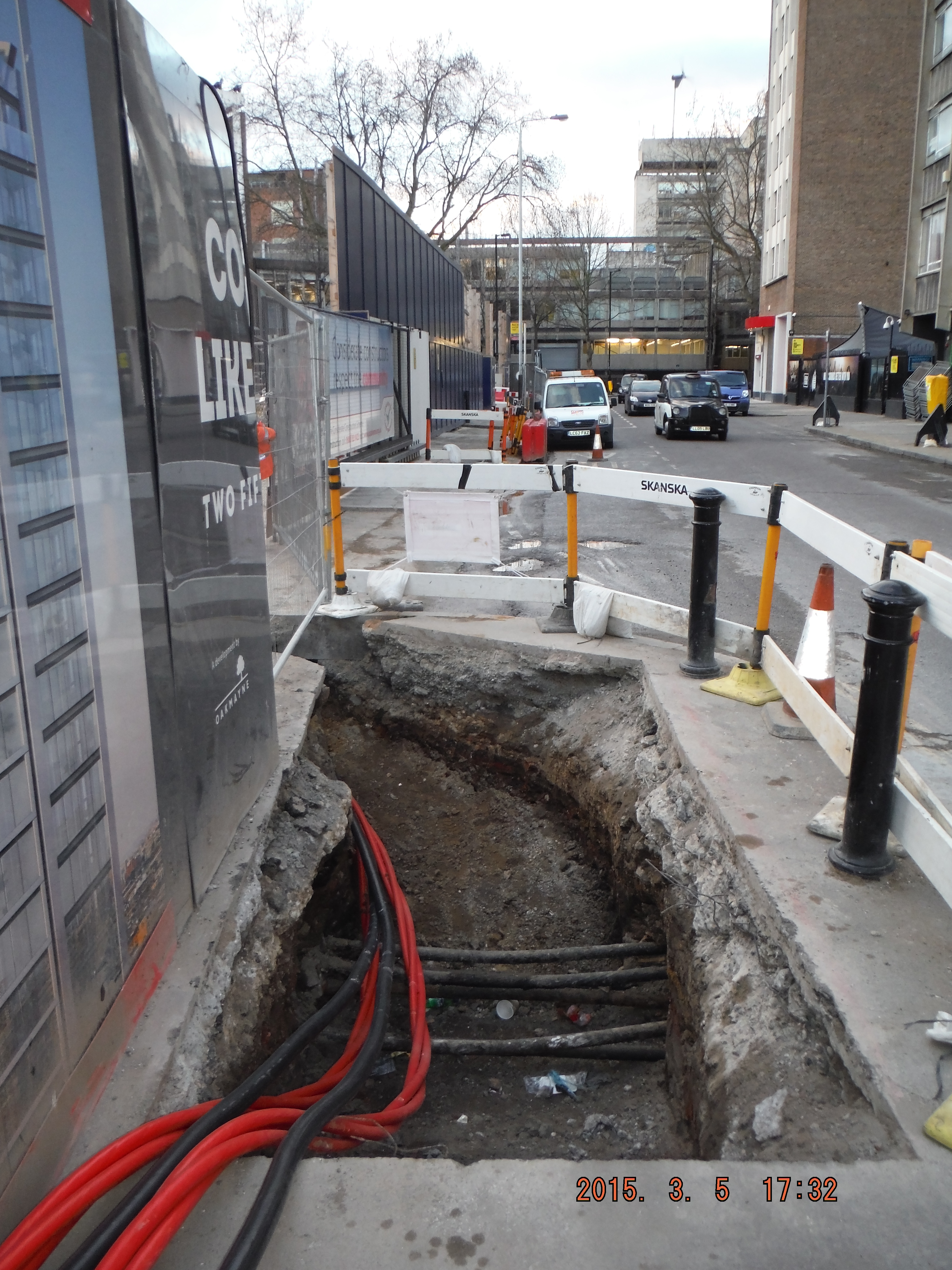
The hoarding move is progressing, but add in moving kentledge blocks close to a 3m deep excavation and a busy bus lane/rat run/cycle super highway there is room for error. Mitigation has been practical though – specific site safety briefings, inductions, lifting plans, segregation fencing and common sense, resulting in steady progress.

Right – hoarding moved within 300mm of blue cycle superhighway Left – heras fencing located where hoarding will be moved to. Note kentledge blocks and proximity to edge of excavation (H&S issues for slinger)
This week I have delivered my first tool box talk – pile mattress construction. Some good revision into the Design Manual for Roads and Bridges (DMRB) (thanks Richard), roller weight, type and width and I am about there. I have learned it is cheaper to order 6F2 (thanks for details of what it can contain Guz/Richard) on a “back load” as we are removing spoil daily. £120 compared to £160, thus making the project manager happy. I am also learning construction terminology: A skip “exchanged” means a fresh one replaces a full one and a skip “collected” is a skip taken away. Apparently “takeaway the full one and bring an empty one” is all too confusing!
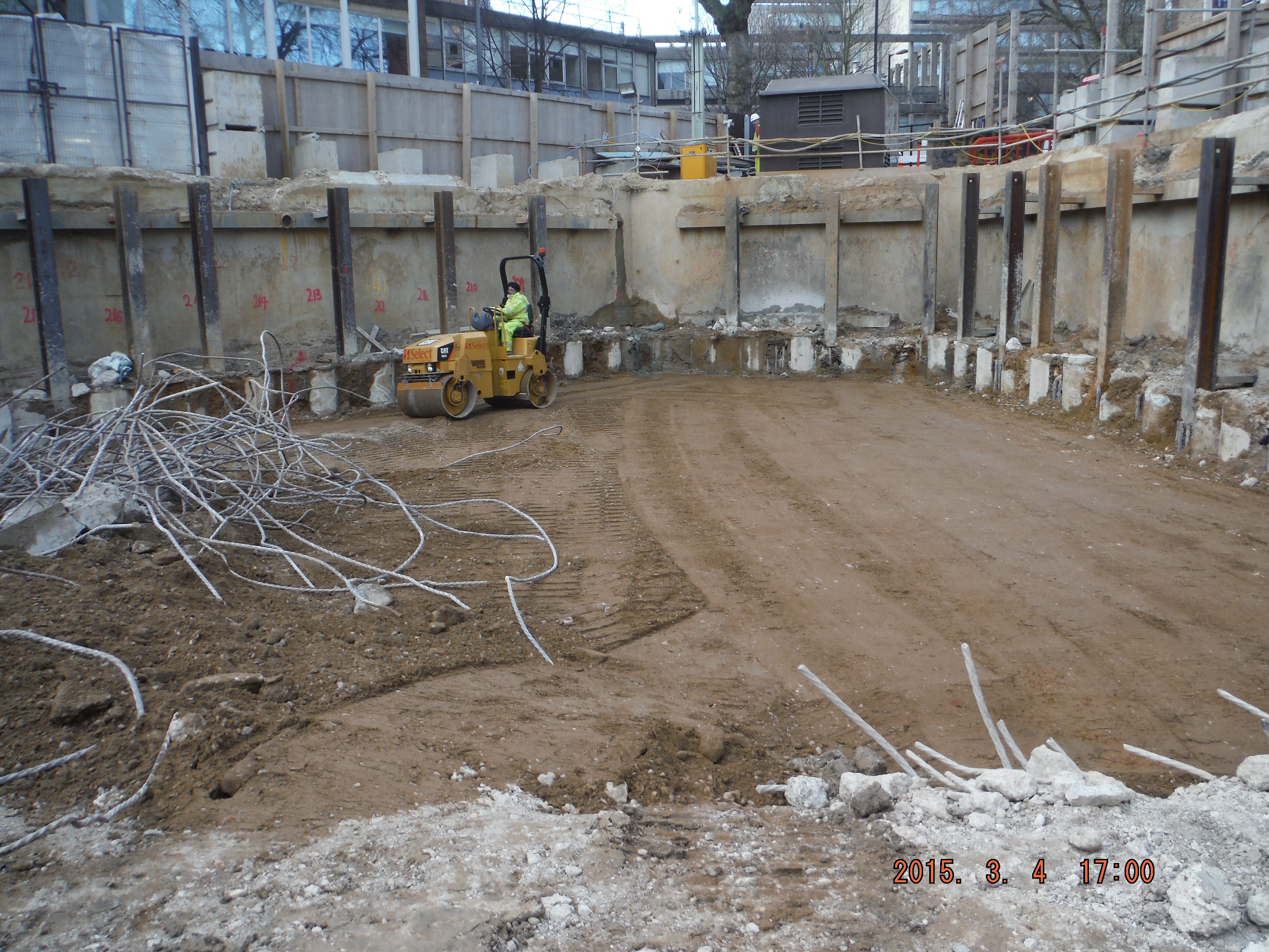
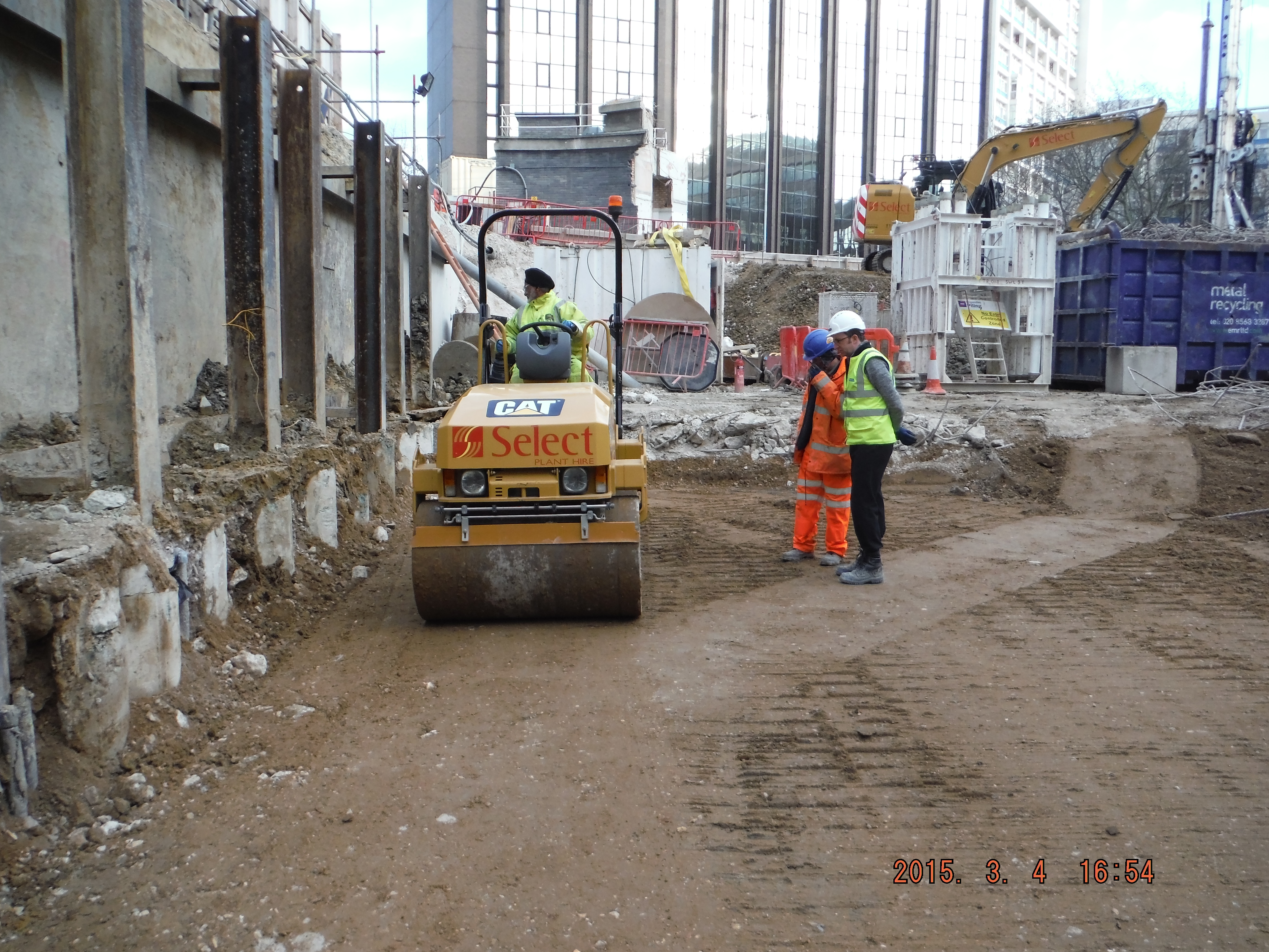
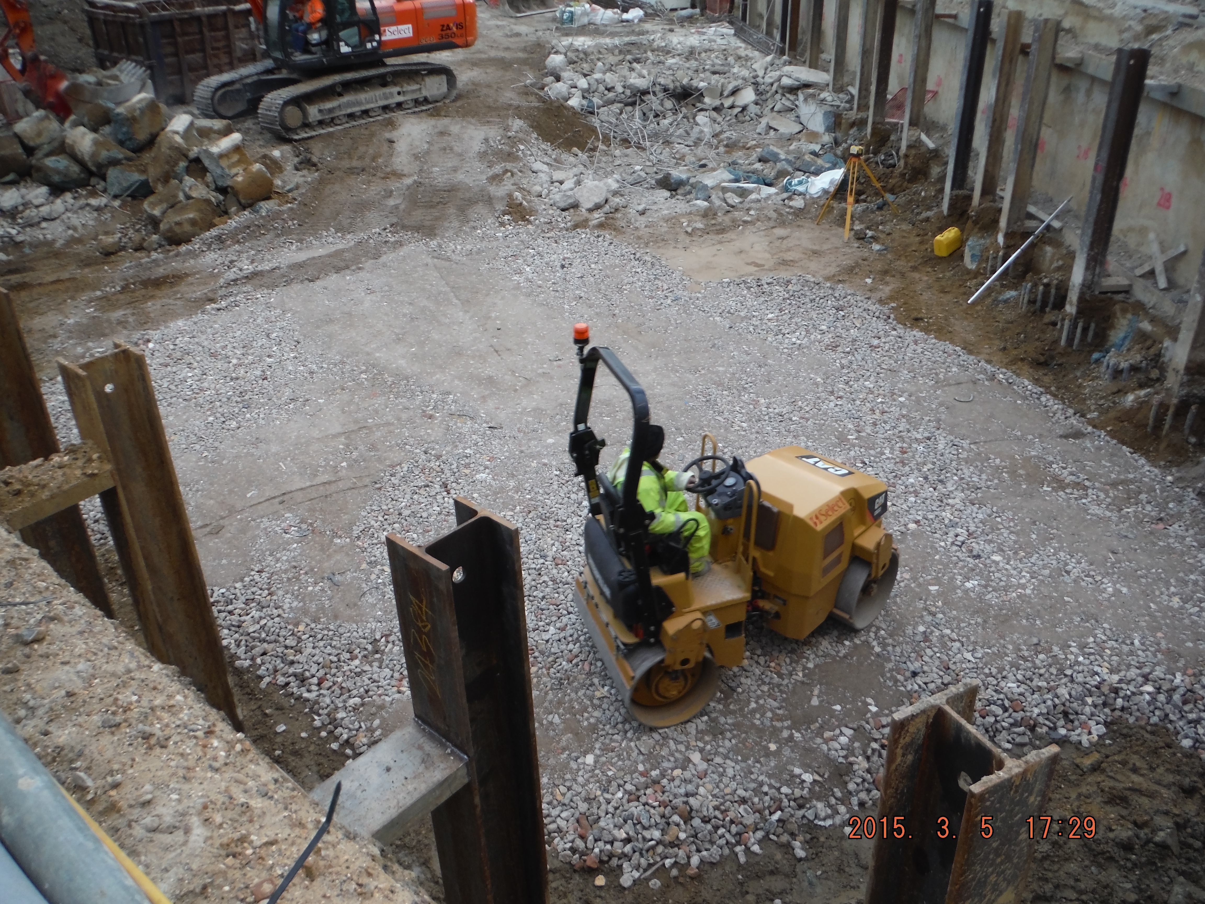
This photo shows compacted river terrace deposits. Rolled with vibratory roller – note depth of compaction – exactly 150mm @ 5 passes – as per the DMRB, now for the 6F2…
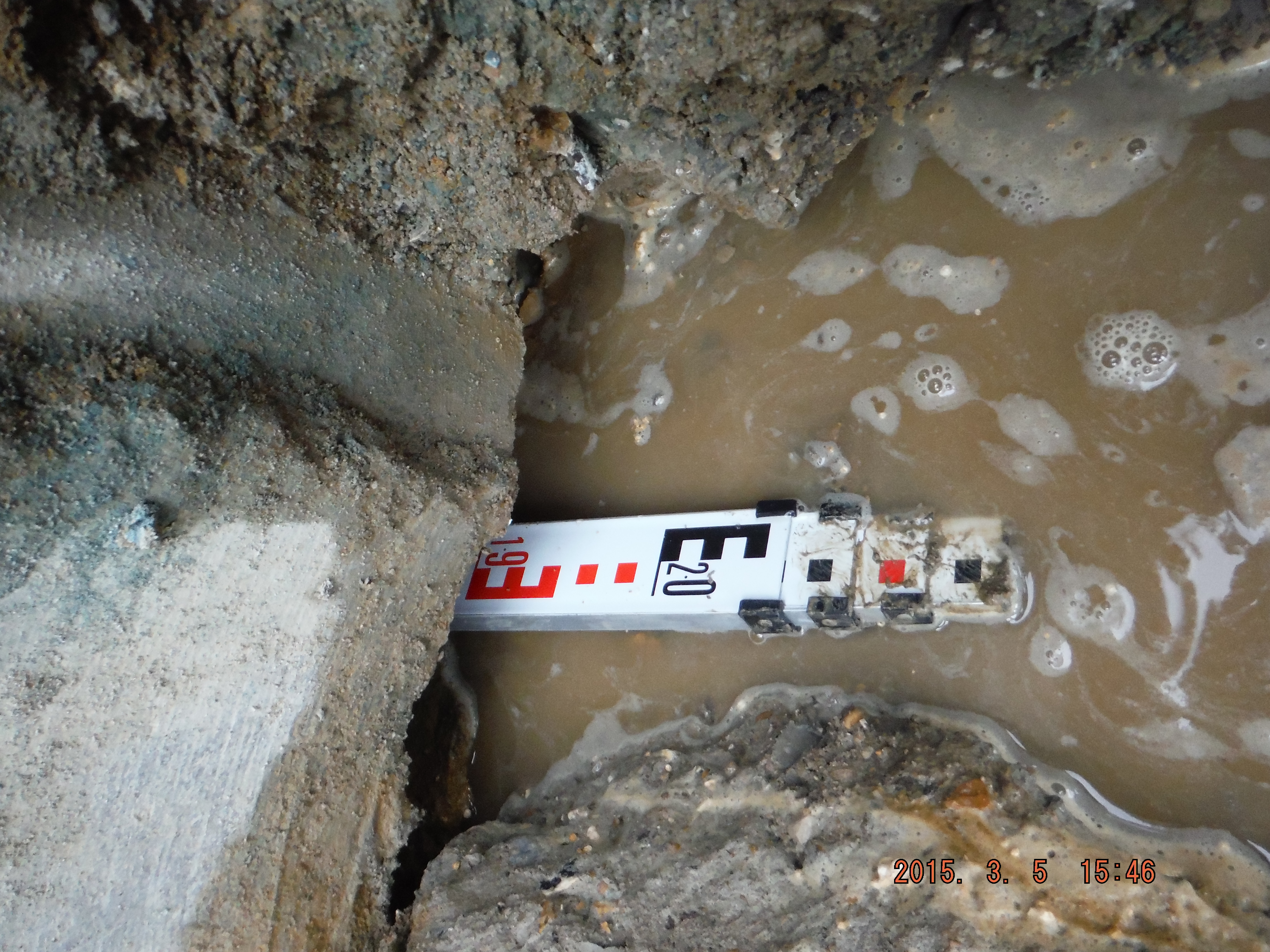
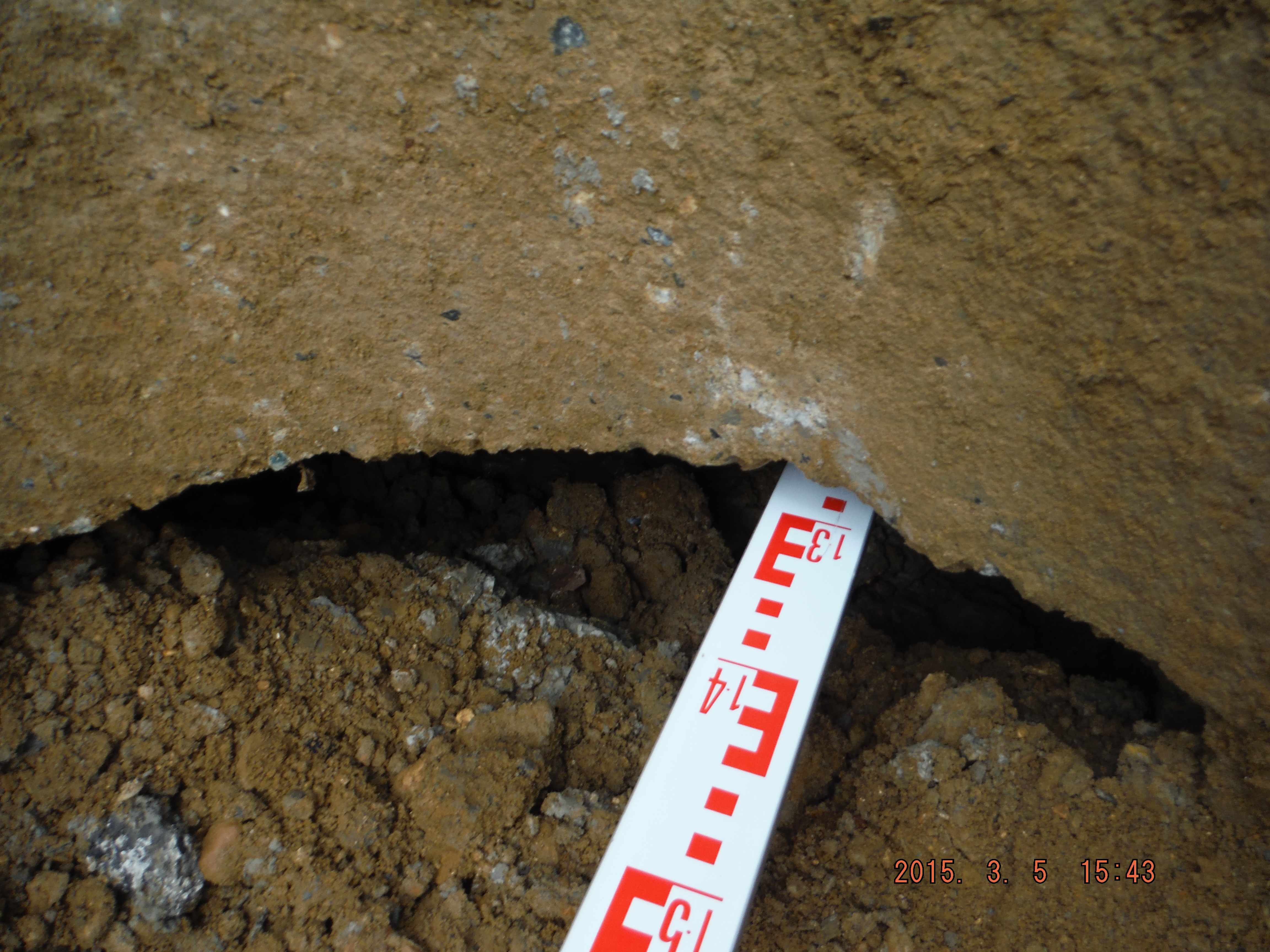
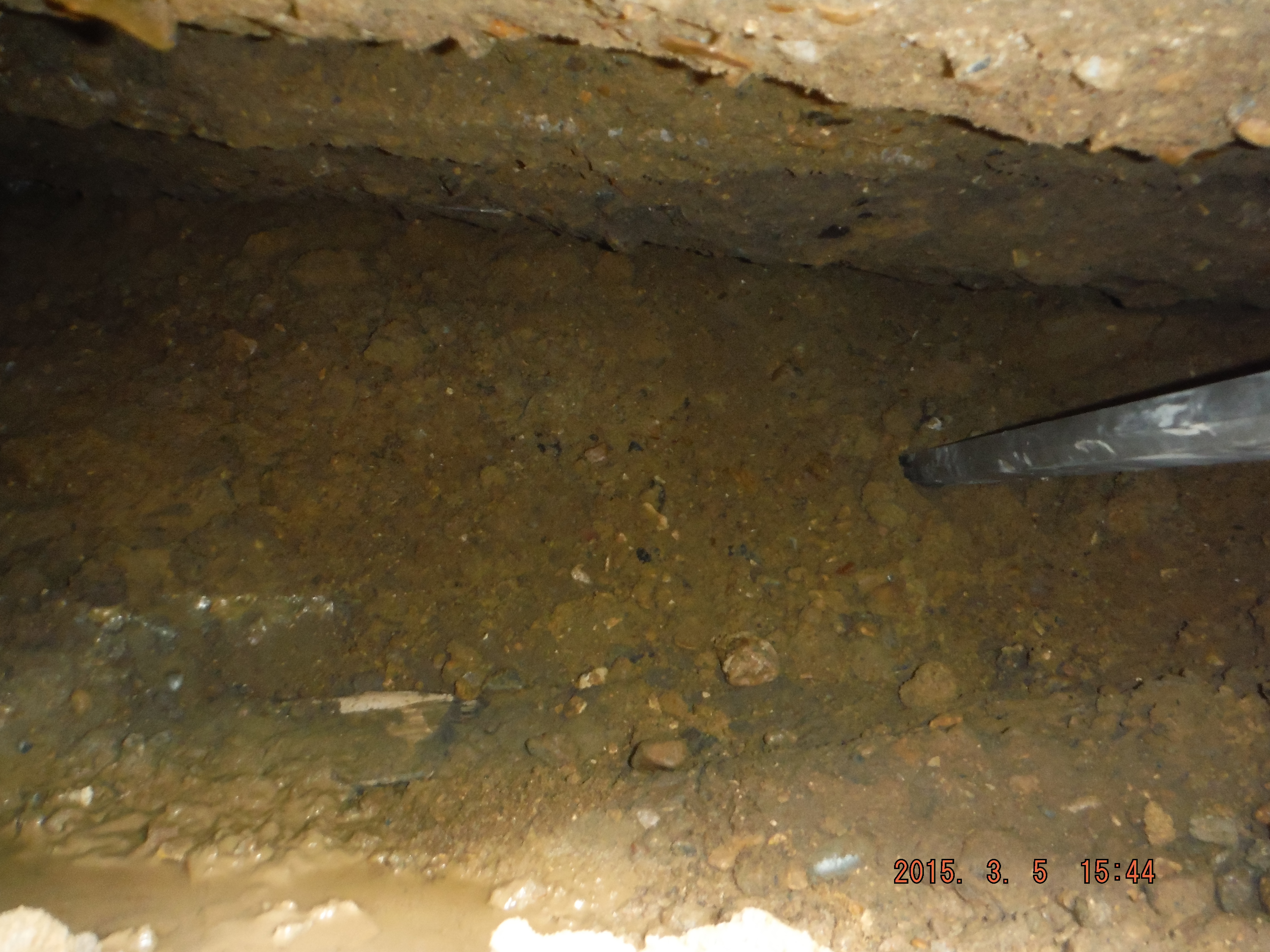
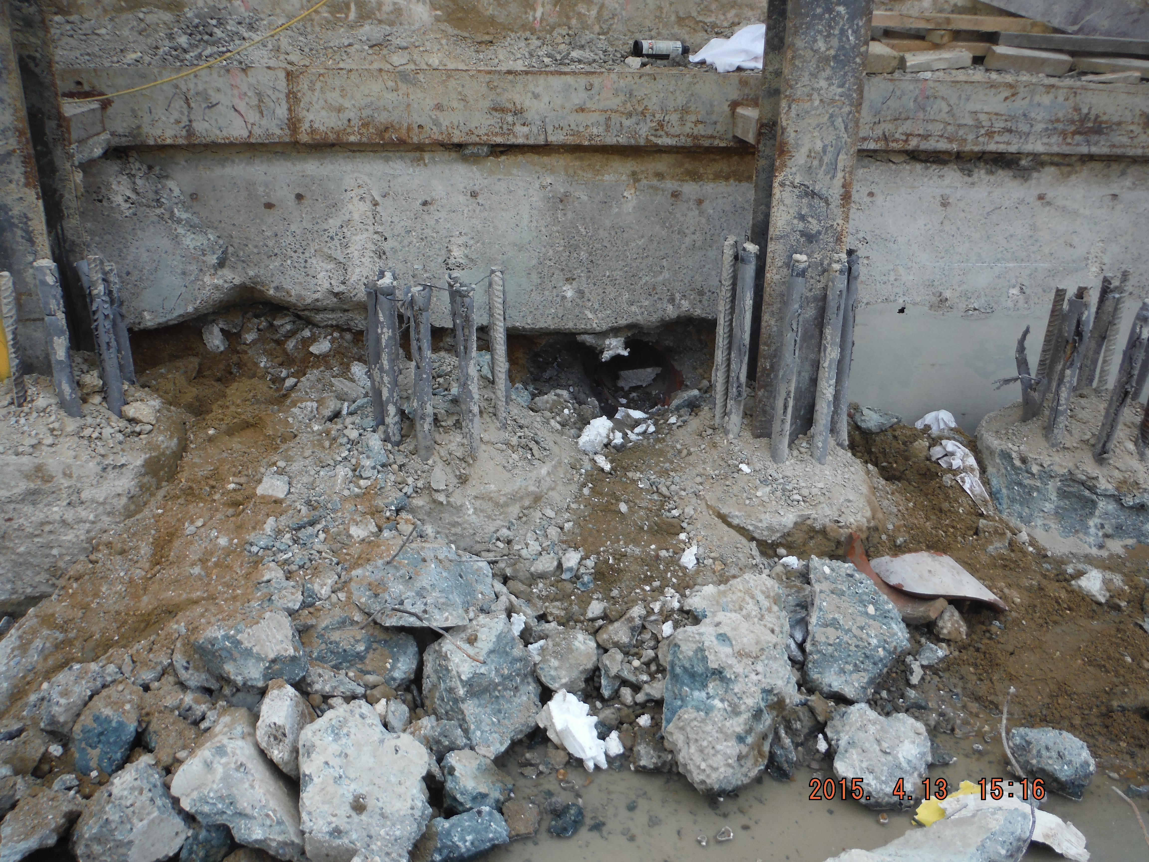
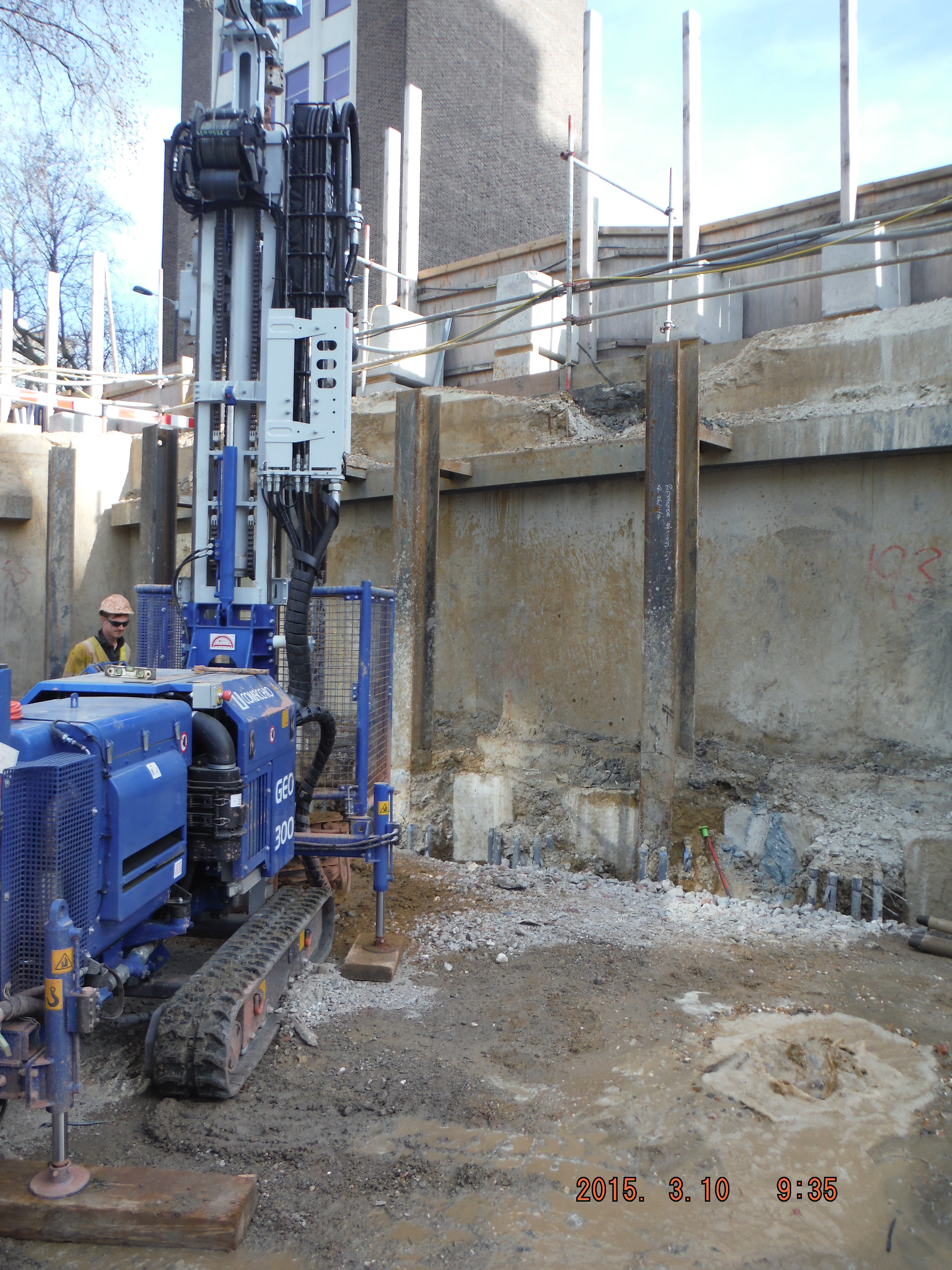
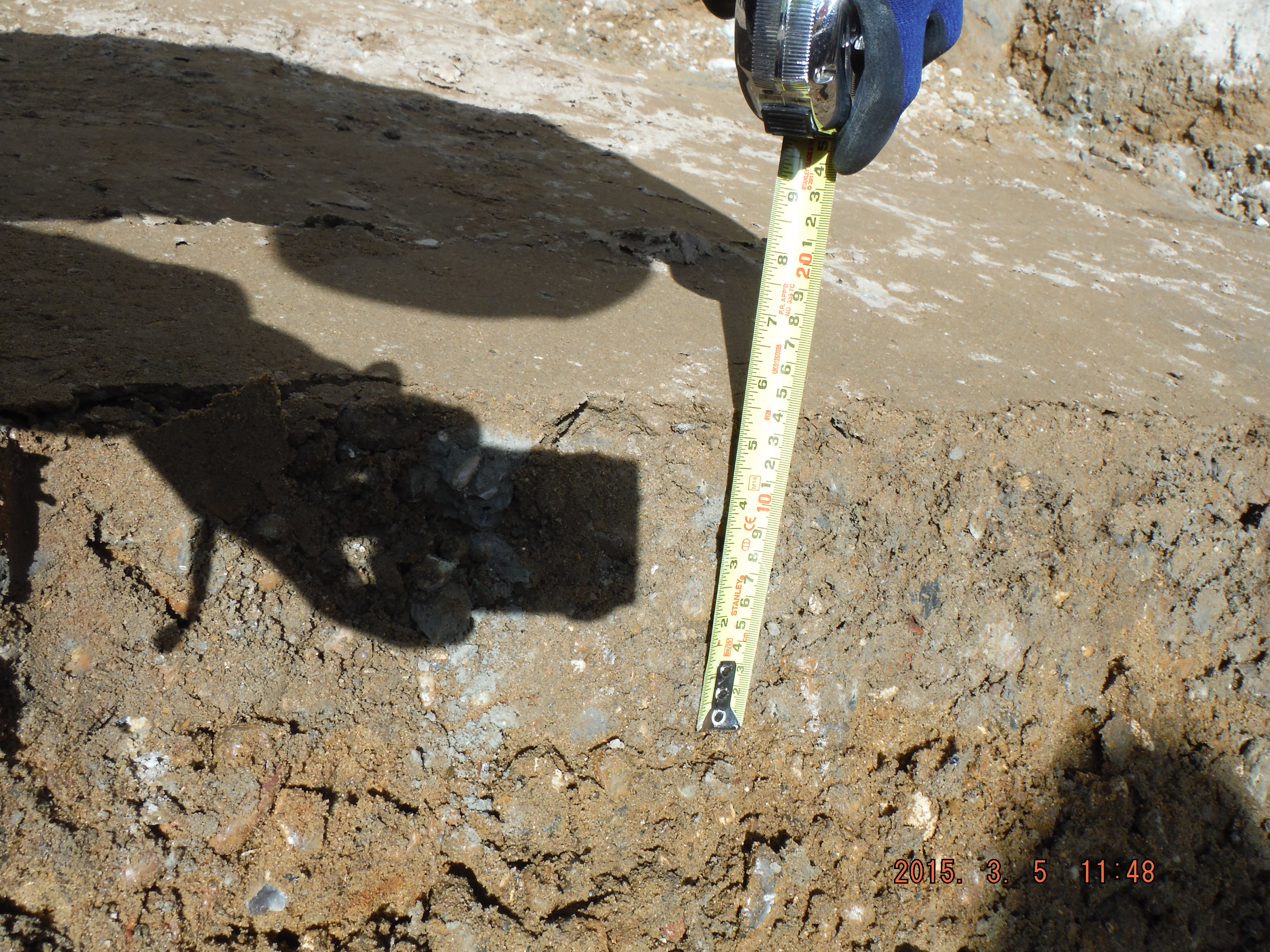
Now for the second part of the pun. After removing the pre-existing slab and some female pile heads it appears I have a floating wall. Well a wall being held up by lateral earth pressure resisted by the king posts and secant pile wall. The hole is about 300mm thick and 1.2 to 2m deep into the underside of the wall.
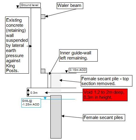
Cross section of existing wall and void identified above female pile which extends up to 2m underneath the wall.
King post protruding from male pile. See void hole to left of king post, between the 2 sets of pile cage reinforcement.
Eventually I had planned to underpin the wall against loose debris in order to construct the capping beam. Looks like that won’t be a problem anymore. Looking into the hole it looks to have been there some time – perhaps the void formed due to water running next to the old slab washing the sand/gravel away (not sure where it has gone to though).
So what to do about the hole… Letter box fill – simply fill the void with concrete from above to close up the void. In the meantime there is already a weekly survey of the wall (mainly to check for deflection into the site, not subsidence of the wall) which has shown almost no movement so I am hoping that it remains that way for a few days longer. We only found the hole today so I am yet to resolve the issue, but as a consideration, if filling with concrete is done it’s roughly a volume of 1.4m (average) by 0.3m thick and extends along about 50m of perimeter so 21m³. Assume £100 per m³ and we are talking over £2000 at this stage and the void may well continue further around the site. Not huge but who pays, client, subcontractor or main contractor…