Archive
Superstructures, Site Visits & Surveys
SUPERSTRUCTURE
Maximising space and rationalizing the use of steel and concrete in Project Armada (The London Development) continues….. along of course with weekly Client changes to floor plans! The link to ‘design development’ is becoming increasingly tenuous as the completion of Stage D approaches. Demolition planning has started and the detailed Architects (conveniently based in New York!) have started detailing the retaining wall and foundation proposed scheme. In terms of a design objectives and development, The London Development has many similarities to the nearly completed Heron Project which I visited last week.
SITE VISIT
The Heron. WSP have recently completed Milton Court (now to be known as ‘The Heron’ and the Guildhall School of Music and Drama). The building is a 36 storey development comprising a six storey lower level structure for the Guildhall and a residential tower above the school. The unique nature of the building resulted in some very interesting design features. The main objectives were to provide an efficient a buildable scheme with minimum quantities of raw materials (i.e. minimize shear walls and transfer structures). Design development to Stage D recommended to following key elements
1. Steel Framed: Concert hall & foyer structure providing slim but strong vertical structure and address buildability issues associated with the ‘box-in-box- approach to acoustic performance.
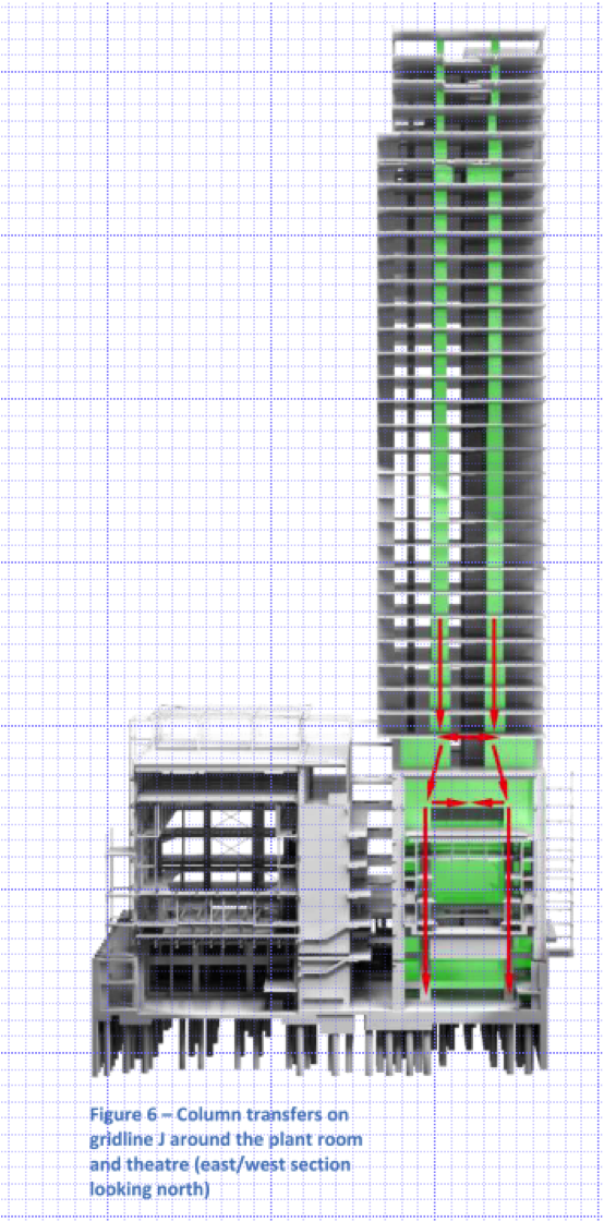
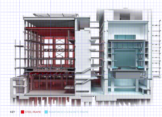 2. Concrete Framed: Tower and teaching theatre, compatible RC for the theatre and PT for the tower to provide flat soffits to all floor plates, good acoustic separation and a maximum number of floors within the stack and height restriction.
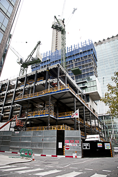
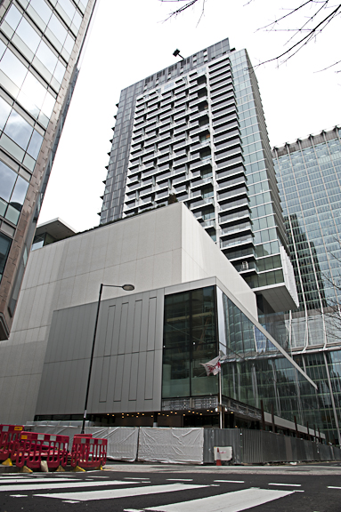
The Heron – before and after.
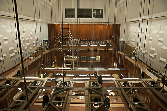
Steel-framed concert hall.
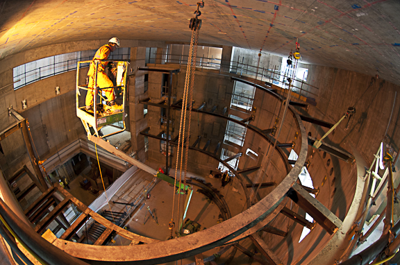
Concrete-framed theatre below residential tower.
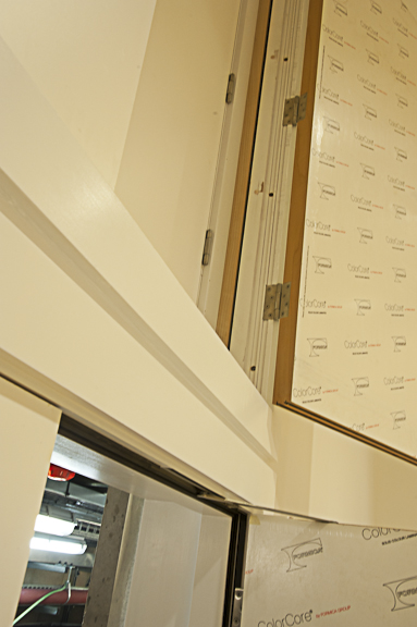
‘Box-in-Box’ construction joint, note separation void between boxes.
SURVEYS
Water Leakage Survey. Heron is one of London’s principal property developers. As part of the development The Heron acquired some basement space under the road, through to some car parking spaces in the Barbican. The acquisition of additional space in a 1960s development however comes at a price beyond that of the space alone. Movement joints within the Barbican podium have deteriorated such that water leaks onto Client’s potential parking spaces, and the basement on the other side of the road is now leaking. I had been initially tasked with providing retrofit waterproofing solutions for the podium slab, before the basement was also identified as leaking…!
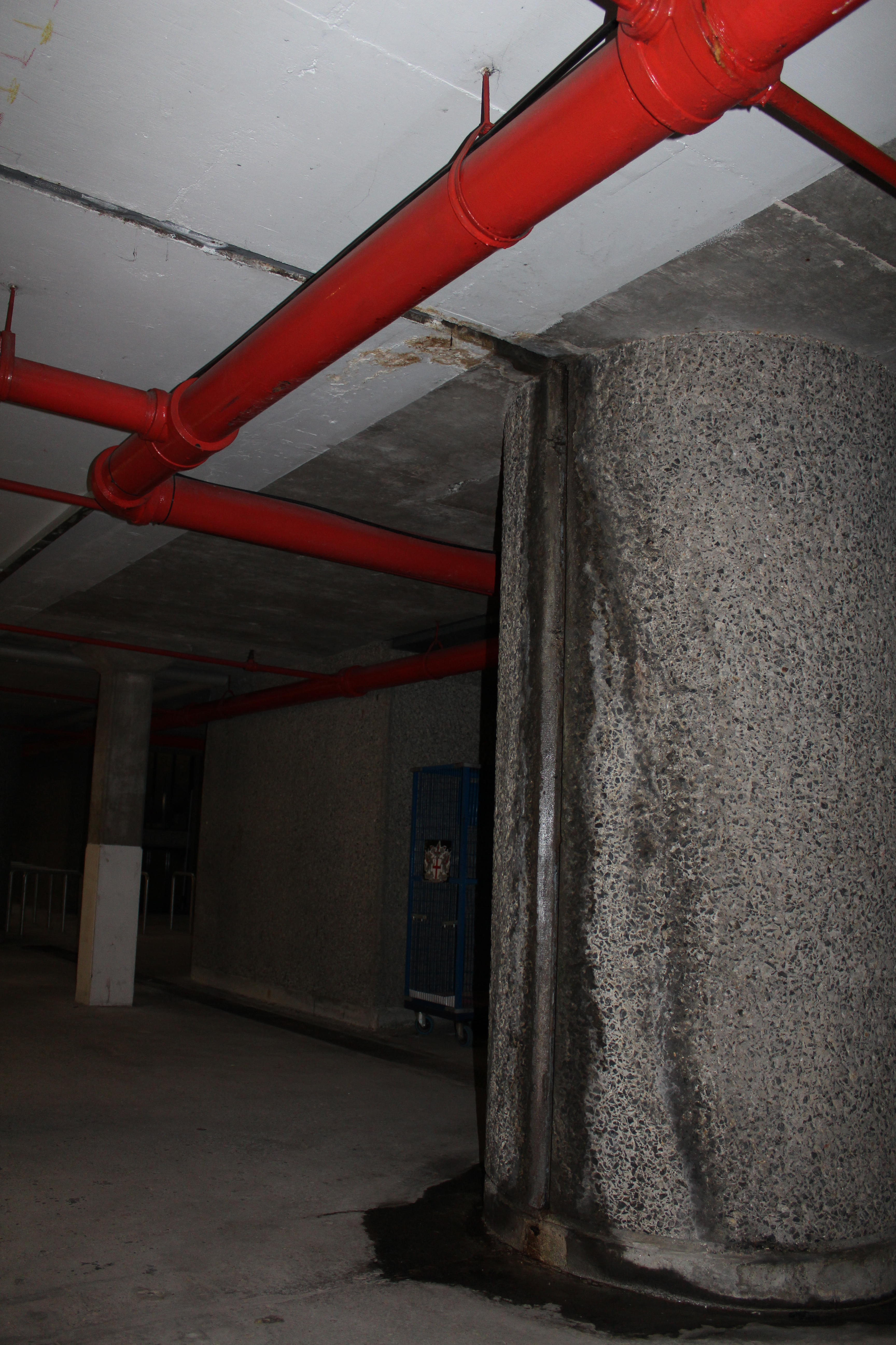
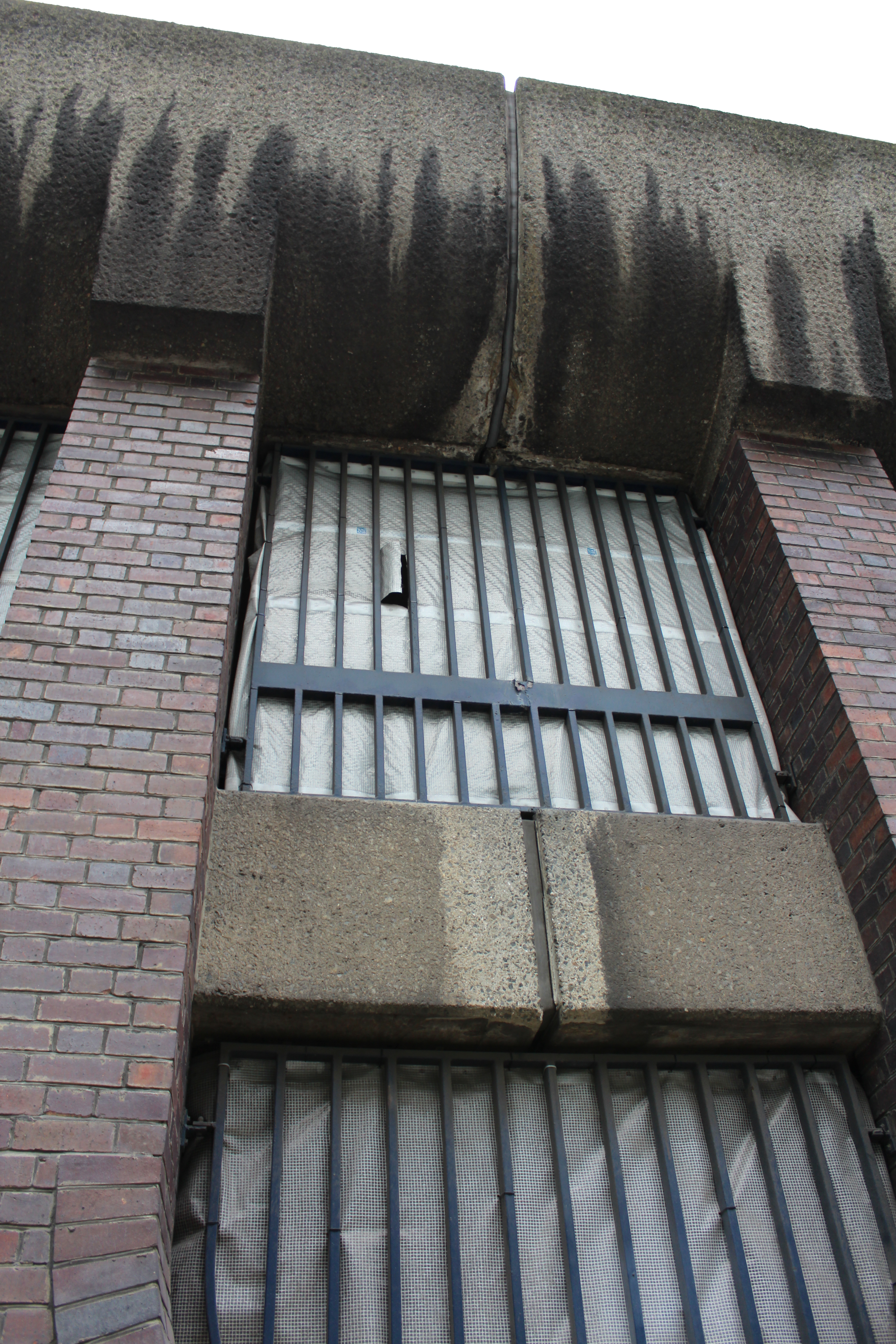
Movement joint in car park column and podium slab.
The picture below was taken 2 hours into the site visit to determine the cause of the problem and agree possible solutions. In attendance where the Client, the Heron Project Managers, the contractor SRM, City of London Surveyors, WSP, representatives from the Barbican. A total of 8! The eventual outcome of the visit was that the two issues were either mutually exclusive or the leaking basement was as a result of the leaking podium slab. City of London roads are treated as structures (i.e. the surface is deemed to be an impermeable layer) and as such additional waterproofing measures are not incorporated into road build up. Fine, until the road is dug up for services installation and maintenance! The waterproofing at site boundaries as specified by WSP does not extend the full pavement width and is not incorporated under the pavement lights adjacent to the Barbican car park. A number of possibilities were identified, all of which would see financial responsibility with a different party – funny how that added at least an hour onto the investigations! It was decided that a water test be carried out by the contractor using a Barbican fire hydrant and coloured dyes to establish the source of the problem……. so look forward to more exciting photos next time in colour!!! In conclusion, water is extremely difficult to trace through structures!

The water source identification team adjacent to the Barbican on the left hand side.
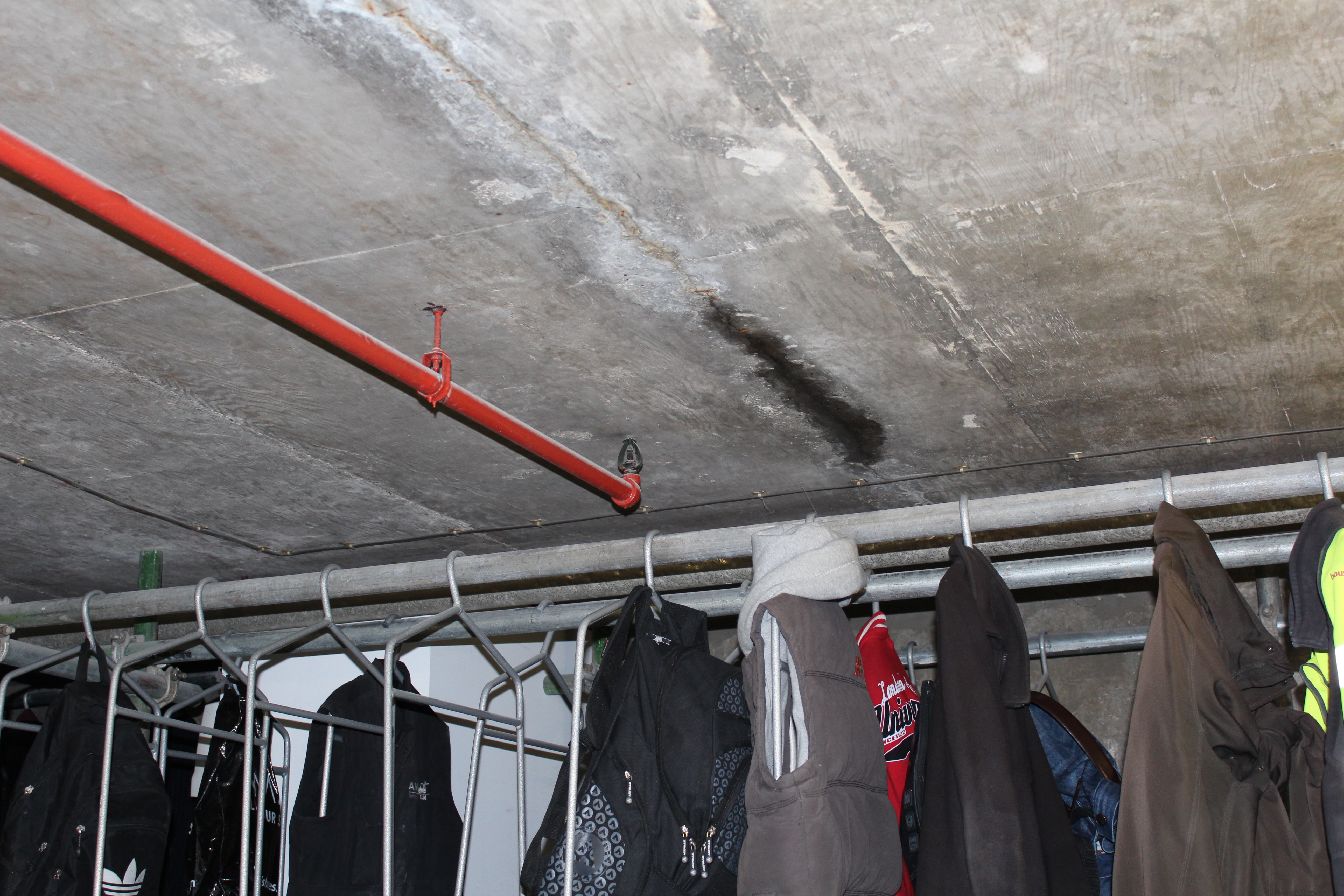
Tracing the water through to the Heron basement (on the right hand side of the above picture).
Employee Survey. On return from the site survey, I was approached by one of the Directors about my thoughts on the WSP employee survey, which are now mandatory in almost all large UK firms. He told me that the Structures department boss was very disappointed, surprised and concerned about the results. He asked me to put a few bullet points together (from an outside/military perspective) for a meeting the following day. After a year in industry these were my slightly de-militarised thoughts:
1. Survey results. Unfortunately I have not yet seen the survey results, however, from what you said I understand that there was a general consensus of apathy and negativity towards the way people feel they are managed and the company in general? The two main reasons people fail to complete, or adopt a ‘whatever’ attitude towards surveys is that they either:
a. Don’t believe they will be listened to.
b. Don’t believe that actions will be taken from the results.
This causes results to be skewed towards those who completed the survey (i.e. highly satisfied or disgruntled). Before deciding on any action, it is therefore important to fully analyse the results and carry out further investigation if required (i.e. interviews or meetings to determine the crux of the issues). For future surveys, techniques to maximise employee participation could be used (e.g. one company used charitable donations post 50% completion in individual units).
2. Response to survey. The next stage is demonstrating to employees that their opinions count and that they are a valued part of the decision making process. This can be simply achieved by communicating what the survey said and what actions have been taken as a result of employee feedback.
3. Engagement. Fundamental to dissatisfaction is an unengaged workforce. Engagement is quite simply meeting basic, social and esteem requirements of employees. Research show that “people join an organisation but leave a manager”! Engaged employees are proven more likely to share their views with their managers, take less sick days, have improved performance and productivity and be more innovative. Engagement is a reflection of a manager’s individual leadership qualities, and will only happen if managers have a clear understanding and are committed to realising the benefits of motivated and value-adding employees. This requires buy-in from all levels of the organisation.
4. Managers responsibilities. Every employee is different and hence effective engagement requires a very personal style of leadership. This involves managers making every effort to understand the needs and aspirations of their team (both within an individual and group context). This can be achieved through regular meaningful engagement: informal (daily/weekly), formal (6 monthly annual performance and potential reports and PDRs). Goals should be set at the start of every project which are clear and realistic, feedback should be immediate (and honest) and every effort should be made to match skill and challenge levels appropriately.
5. Employee responsibilities. Employees should be incentivised to optimise their performance and potential, as well as contributing to the wider company ethos. Manager’s reports should reflect employees levels of engagement, and they should be rewarded accordingly (responsibility, position, project assignment, promotion*). Engaged employees should be empowered to instigate change, from changing dysfunctional or unpopular processes, to tasking graduate engineers to get maximum participation at a company team building event.
*I appreciate that there are always financial constraints however, fewer quality, ‘engaged’ and appropriately salaried personnel are much more valuable than many short-term ‘unengaged’ employees.
I have since been asked to a follow up meeting with HR…… sports afternoon Wednesdays, early knock off Fridays and ‘enforced fun’ socials here we come….!!!!
Big buildings, banks and basements
Project Armada
I have been assigned to The London Development which is the design and construction of a nine storey, one million square foot Goldman Sachs headquarters building. The project is at stage C-D and I have been tasked with the basement, retaining walls and raft foundation aspects.
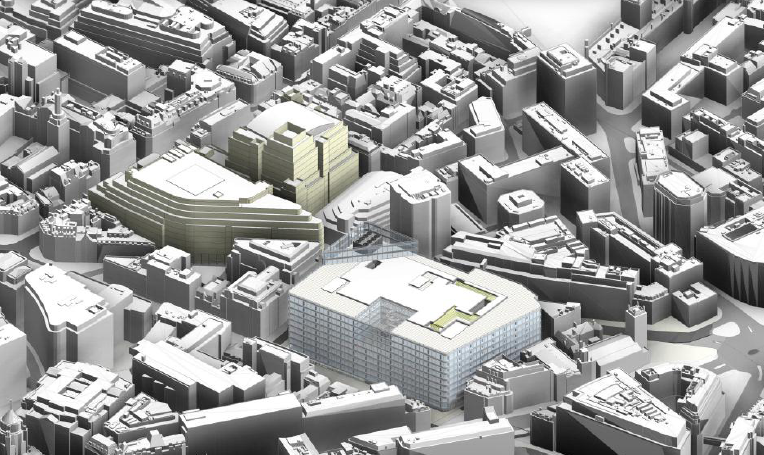
Architects image: the maximum height of the building is limited by the Greenwich Park to St. Paul’s viewing corridor, creating a demand to maximise the floor area .
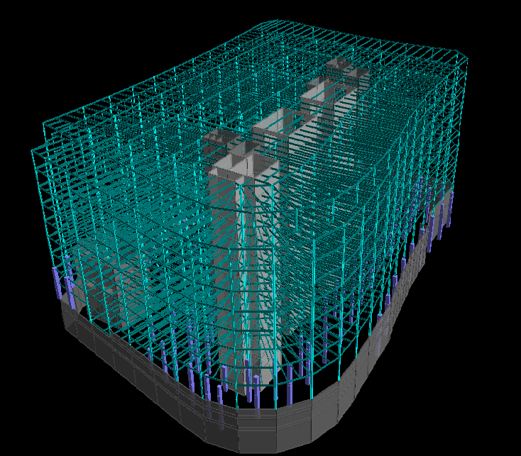
The initial superstructure model with 9th iteration of core walls layout and 4th iteration of column grid layout!
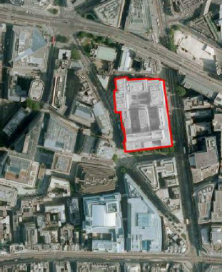
Site on Fleet Street in the City of London currently occupied by 2 buildings.
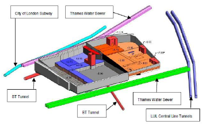
In addition to the above ground site constraints, The London Development is underlain (aside from the old Fleet River) by several below ground tunnels, chambers and utilities. Of which three substations and a access lift shaft have to be maintained within the basement, making the construction sequencing a critical component to the design.
Design Lessons Learnt
Having completed 6 days of Structures Graduate Proficiency training over the last couple of months, it is clearly apparent that aside from the core syllabus of revising first principles and Eurocodes, the priority is to teach graduates how to design to save money and make money! i.e. how to incorporate economy into design and how to get the right answers (to an appropriate level) in as little time as possible! Given the size of buildings WSP Structures department generally deal with, this skill is key to maintaing a profit margin – time is most definitely money all the way to the 70th floor! Perfecting the art (certainly during the initial design phases) as far as I have ascertained, seems to be rules of thumb first followed by optimisation through software. The first comes naturally to those with experience, or eventually with a bit of guidance for graduates or newbees! A few new designers lessons learnt so far:
1. Apply rules of thumb (i.e. quick designers assessments of member sizes and configurations) to the problem first, just to get an idea of what the loads and forces are likely to be so that you know if your answers are at least in the right ball park. These are contained within most guides but do not require trawling through the Eurocodes and should only take less than an hour to produce.
2. Understand the geometry of the problem fully before embarking on any design. I have found drawing lots of sketches and asking colleagues if that is what is required saves a lot of time in the long run. This will firstly ensure your part of the design fits within the overall structure (and you are using the same parameters) but also basic components like the slab is spanning in the right direction for example!
3. Consider construction aspects in the design Intrinsically tied to the cost of materials is the cost of construction. Whilst the consultant does not price the construction, the client will soon establish how economical the design is when the contractors submit their tenders. In my case, I had to give the Client a ribbed slab vs composite slab solution for a bespoke 100 person conference room. Whilst the ribbed slab came out considerably deeper, the additional cost of bringing steel into the construction sequence to maximise clear floor to ceiling height will have to be weighed up by the Client. Another aspect which I hadn’t initially considered was additional opportunities for temporary works savings, for example ensuring the beam is the same height as the ribbed slab, thus increasing the width with a set depth of the beam to reach the required capacity. Where the designer employs these techniques however, it is often then necessary to explain the reasoning to the QS who may only be looking at the cost of materials!
4. Initial design = initial design After spending hours producing reams of detailed designs, the client would then want a column grid change or an adjustment to the proposed floor plan! Whilst this should theoretically stop after the agreed “design freeze” date, either the date continues to slip or it will happen anyway and a concurrent commercial debate about whether it is design development or a change in specification will ensue! The answer at engineer level is to minimise detailed calculations at this stage and maximise use of spreadsheets or software where parameters can be easily changed. This also ensures that unnecessary time is not logged to the project which will be required during the detailed design stage.
Site Visit
I visited the One Blackfriars site, a 170m residential and commercial tower with the geotechnical and structural engineer responsible for the groundworks phase of the construction. Much like the Shard, construction will be simultaneous top down, bottom up construction, hence the requirement to install a series of plunge columns and cast the ground slab prior to further excavation.

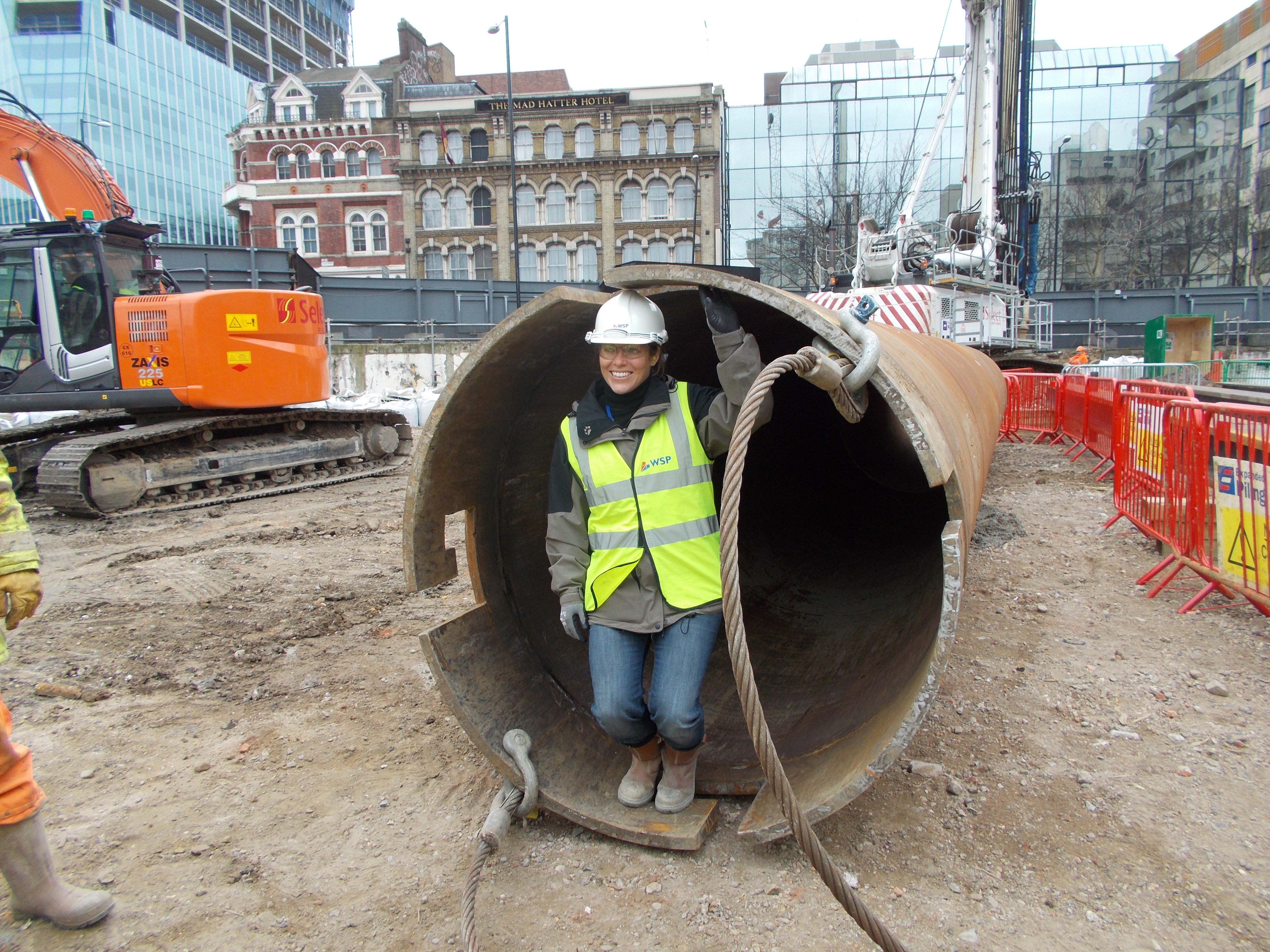
A plunge column casing (of which I was asked to demonstrate how tall is was…almost 6ft…?!)
The contractors were in the process of installing the plunge columns using a best practice technique developed by piling contractors. A bespoke casing was fabricated with guide rails which allowed the column (also fitted with guide posts which can be fabricated to the required length) to be fed into the casing, levelled and hung from a steel beam until the concrete has reached the minimum strength requirement. The size of the columns is dictated by the loads as well as the levels of tolerance required.
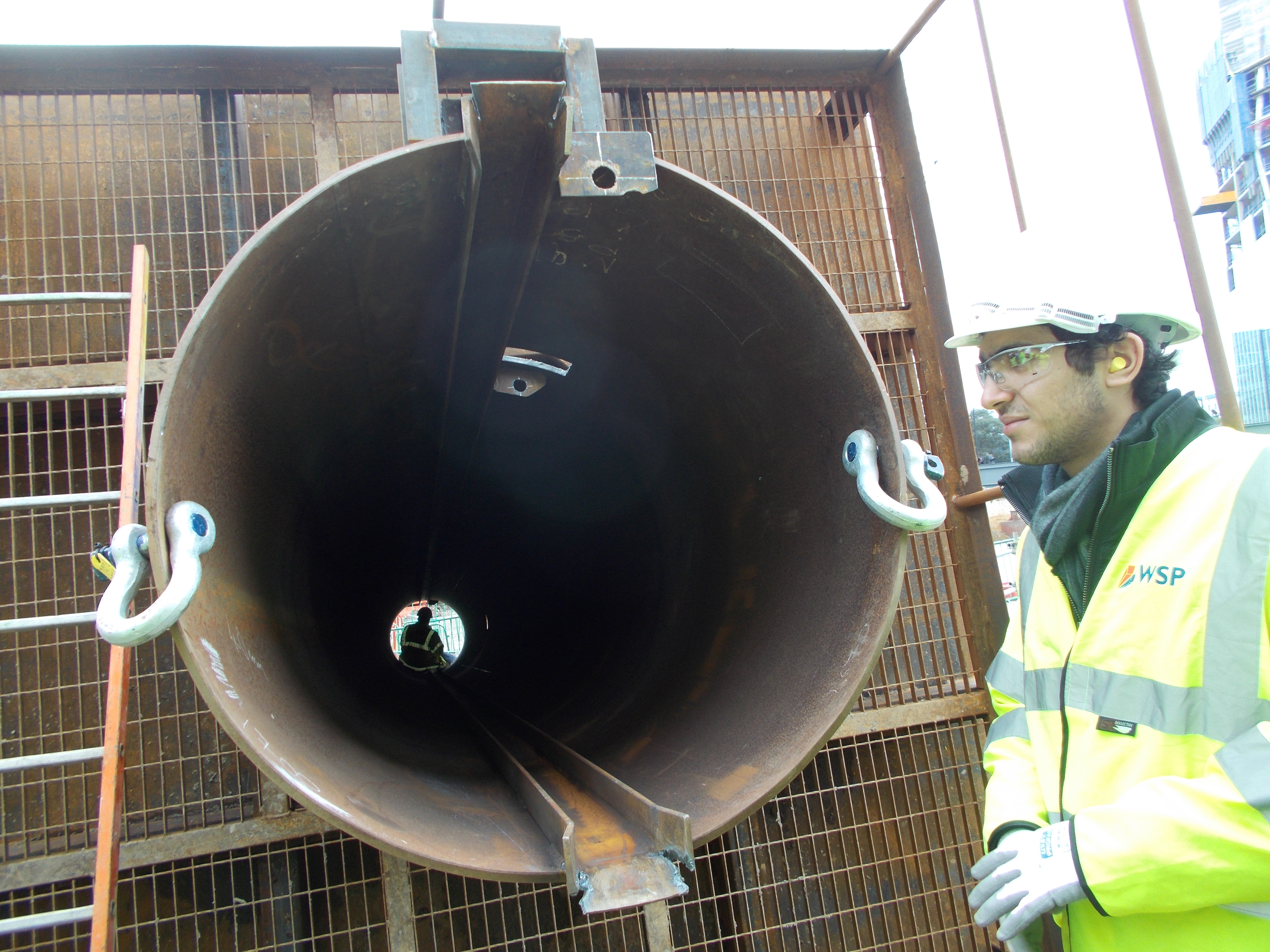
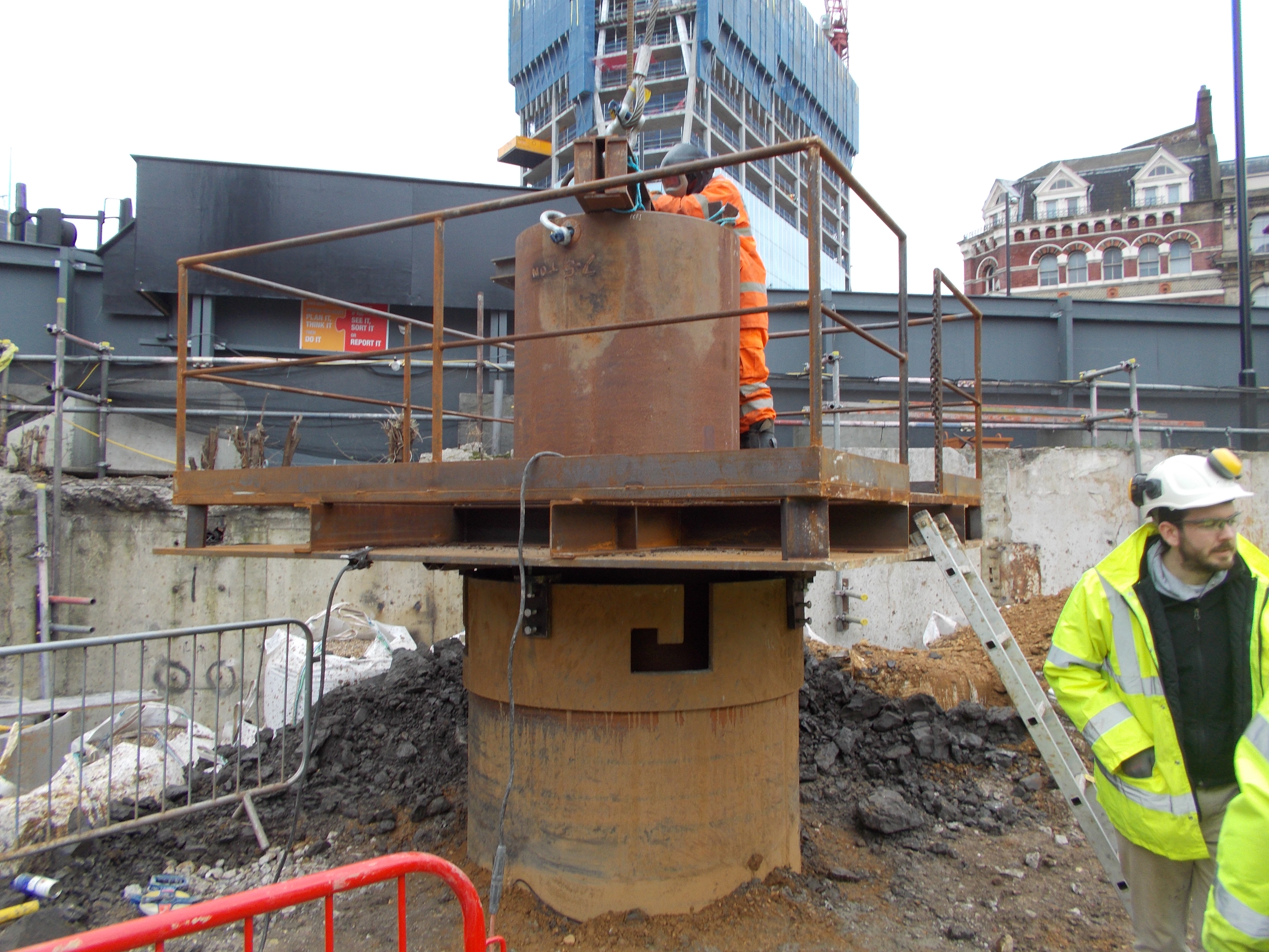
The plunge column installed in the concrete filled pile, hung from the beam shown and welded for security until concrete reaches required strength.
Another best practice technique used on the site was bags of shingle as temporary propping following excavation adjacent to the road, saving on bespoke temporary works and utilising the shingle in the final layer of the plunge column piles. Very Royal Engineers I thought!
A consultant’s perspective……
Six weeks into my design office placement with WSP, I think I have come to understand why consultants are consultants, contractors are contractors and architects are architects….! I was also surprised to discover how quickly I switched allegiances and adopted a consultant’s perspective….nothing to do with the central location, swish office, great coffee machine and invitation to the opening of the Shard of course!
I was asked to contribute to the monthly ‘Knowledge Sharing Forum’, and conscious that I was highly unlikely to have discovered anything structurally ground breaking worthy of dissemination to the WSP Structures department, I went for a comparison of a design office and the military! Interestingly, I found the design office to be more comparable in many respects than site (summarised in the meeting minutes below):
Major Rachel Beszant is on secondment from the Royal Engineers. From her first month in WSP she has drawn five key similarities, and two differences to the military:
The similarities are:
- There is a strong teamwork aspect to our business – though we are each capable as individuals we can only deliver the projects we do working in teams.
- Within each team there is a structured hierarchy. This is necessary to ensure accountability and allocation of responsibility
- Goalposts change throughout the lifetime of a project. Whilst in the Army this may be due to a change of political leadership in our business we are faced with clients and architects changing their minds and on-site discoveries.
- Communication is vital to the success of our projects. This is particularly well done through the structures portal.
- People are the centre of the organisation and success is reliant on the skills and expertise they have.
The main differences being:
- As a private company WSP has to maintain commercial competitiveness. Money does unfortunately drive many of the decisions we make, though this does also ensure we are efficient.
- There are no Sergeant-Majors enforcing discipline on the second floor!
I fear if my turn comes around again before July I may have to work on a groundbreaking discovery!
Aside from organisational and people observations, I can confirm that geotechnical parameters and water levels are indeed as vague as John warned us… and London is sat on a lot of water! The British Standard generation hate the EuroCodes….. and software packages are almost as reluctant to change as the BS era! Software modelling is the way forward as long as you understand the programme and know how to fix the errors, and hand calculations are key for checking, but any longer than 2 pages are reserved for graduates (or RE attachment officers!!)
Cofferdams, Concrete and Coming to the End…
Cofferdams, Concrete and Coming to an End….
The last few weeks on site saw the start of the cofferdam preparations, which from a Monitoring Manager perspective I had a key negotiating and decision making role between third parties, the Client and Vinci. The main issue was the level and type of monitoring that would have to be installed prior, during and after the cofferdam works (sheet piling, dewatering, construction of cofferdam, de-construction and construction of tunnel) in order to satisfy all parties.

The Contractor’s consultant, convinced of the adequacy of his design did not deem any necessary, the Client was hinting at costly underwater scanning technology, Thames Water wanted the moon on a stick and London City Airport (originating from BA demands) wanted to charge 10 passenger seats for the additional risk of construction works in case of a plane crash! Cut a long story short, the Thames Water issue was one of vibration, resolved by rearranging the sequencing and location of sheet piling works and proving that the service tunnel was actually steel and not iron! A metallurgical test was carried out after we showed Thames Water a photograph of a drawing taking during a trip to the London Docklands Museum which showed the pipe as steel! This doubled the allowable vibration limits solving at least one the the problems.

A monitoring proposal was eventually agreed which included prop , sheet pile, tie and dock wall monitoring. The designer was most concerned about deflection of the southern dock wall (which is sheet piled and tied following expansion works in the 50s) during dewatering. The siting and operation of the increased monitoring formed an integral part of the cofferdam planning process, since Crossrail will not allow any works to proceed without monitoring in place. This clause also lost a week of production days after a £25k Total Station was stolen from the West Tunnel Portal! Ironically this, and the Client EWN regarding monitoring requirements for the cofferdam, went a long way in getting the QS’s to acknowledge EWNs and CEs from the monitoring subcontractor (who were already owed over £150k)!

Monitoring issues increased exponential as works progressed elsewhere on the site, of note was movement of the DLR Prince Regent Street Station as a result of major excavation works adjacent to the retaining wall. Fortunately because the excavation was only 400m lower that the final structural slab level (in order to carry out pile remedial works before laying the Load Transfer Platform (LTP)), the designer was probably more worried that the Contractor! Hence, we had a number of very collaborative Engineer Review Meetings to conclude that the station was a piled box section, movement was conversant (albeit not entirely predicted) with the works and ground conditions and stabilisation was eventually established!

In addition to normal works, the Limo site a few kms west of the site (where a TBM shaft had been constructed) turned off their dewatering in November which had provided us with 3m of draw down. There was then a 2 week period before we were had planned to turn on our Thannet Wells in preparation for the Central Sump shaft deepening. It was interesting to monitor the effects, heave in the central section and increased water flow rates from our existing Chalk wells. When we started to get our feet wet in the tunnel however, I managed to negotiate the Thannet dewatering date forward (at a cost of £800) – there had to be some perks to the Monitoring Manager job!
After severe delays with piling, and a curious bout of concrete chicken pocks (eventually put down to admixture quantities, resulting in an entire bay strip out), the reinforced concrete slab programme started to progress well on both the east and west surface rail.


Drilling and Grouting works in the tunnel eventually finished at the revised extent (70m less that the planned invert replacement length (although the same as the OCI agreed length). The delay, largely due to ground conditions initiated a design review of the invert replacement extents. Vinci claimed it would cost £10m extra to do the extra 70m predominantly in the River Terrace Deposits (of which £4m were preliminary costs). Crossrail has their Designers go back to the railtrack designers and make every tweak possible to achieve the requisite rail alignment within the OCI extent. The Client won and as I left, were considering (albeit impossible to contractually implement) a pro-rata deduction based on the fact that Vinci were now not doing ‘£10m’ of work! An illustration on the ‘spirit of mutual cooperation’ by a Client on Cost Plus contract, and a Contractor experiencing the Pain aspect of the Pain/Gain share. After their 12 week (turned 6 month stint at Connaught), Bachy will be returning after Christmas to grout the base of the Dock Walls to form a seal with the Lambeth Group as the 3rd and 4th side of the cofferdam.

In the Tunnel, the negotiation of Invert Replacement Bay and Prop size continues, but Target Cost, progress bonus driven Gallagers are continuing at pace with the Central Box Section replacing the Twin Tunnels. The main issues have been timely issue of levels and reinforcement detailing. However, as Crossrail approach their Dock Passage Closure window (ironically not a Contractual date for Vinci), approvals and acceptances have been much more forthcoming! A major logistical problem was concrete pumping over long distances which was solved by driving the concrete into the tunnel to a concrete pump adjacent to the works. Production time was increased by bringing in additional formwork, mounting it on wheels and moving it from Bay to Bay without the requirement to re-errect it. A commercial issue has been questioning Gallagers on their ‘bonus’ scheme. They believe it drives production and ultimately saves the job money (which having seen the rate of work I would tend to agree), however our QSs do not believe it is conversant with the terms of the contract… the saga continues….


Aside from that, my last job outside the tunnel was planning the Parapet Wall removal which has Traffic Management (liaison with the local council), scaffold, crash desk, temporary propping and achieving requisite levels around existing arches aspects. However, surprisingly the works have been delayed and will not start until after Christmas… Easter… next Christmas… have I become cynical at the end of my Contractor placement??!!

And finally, meet the Team….. my trusty Assistant Site Engineer Alex, the Tunnel Team (with left to right 2 new Assistant Site Engineers, fellow Section Engineer and ‘senior’ Assistant Site Engineer (vying for promotion) Alex…!) the Tunnel Construction Manager (left), mad Irish Foreman (centre) and my line manager the Tunnel and Central Section Production Manager (right), and the Works Manager recently turned Surface Construction Manager.


Client, Contractors & Catastrophic Failures
SURFACE WORKS
Piling
CFA and CMC piling continues, as does rectification works for non-conformance reports (NCRs) (raised by Crossrail and subsequently Vinci and the sub-contractor upon realisation that it is commercially advantageous to flag up your own defects) on 1200 out of 1800 CMC piles. The principal cause of these defects was the use of a crack inducer that had not previously been trialled on this scale. The plastic yellow cone pictured contains a wooden ball which, when filled with grout at high pressure from above acts as a non-return valve forcing the grout out through the sides and hence inducing a crack in the pile. The induced crack, combined with the use of an excavator to crop the piles proved highly ineffective and was eventually replaced by a pile cropper. A 67% defect rate has proved extremely costly, and unfortunately for the sub-contractor and Vinci, unlike the first few piles which disappeared into the river terrace deposits, these NCRs cannot be attributed to unforeseeable ground conditions.


Those rectified CMC piles that have now been accepted by the Client have subsequently been overlain with the Loading Transfer Platform (LTP) and Load Tested in preparation for the reinforced track slab works. There have generally not been any problems with the CFA piles, which have been cut off exposing the starter bars in preparation for the track slab walls and overhead cables.

Reinforced Concrete Delivery
The Vinci delivered reinforced concrete track slab and walls are awaiting final ‘acceptance’ from Crossrail, and a trial has been carried out to refine methodology prior to works commencing. Making good trials will follow to establish best practice for the main works. With a large amount of concreting starting on site (and within the tunnel), Vinci engineers have been receiving in-house training to in order to be able to carry out re-bar and pre and post-pour concrete inspections.


TUNNEL
Temporary Services
Temporary Services have now been 90% installed, partially handed over and the sub-contractor is now in contract in a maintenance contract. Having seen a sub-contract ‘almost’ full circle my main observations and lessons learnt are as follows:
Sufficient time and resources (the right people) should be spent drawing up the scope and specifications – what will be needed during construction (what will be the maximum capacity + contingency) and for final handover (ability to reduce capacity for the Client)? E.g. Having to issue 6 x PMIs for additional power requirements.

Planning should be continuous and communicated to the right people – how will other works interact with the installation, during and after construction. E.g. The Invert Replacement Trial required 4 x M&E services to be moved and the props and temporary works for the main works conflict with the fire main, compressed air line and drainage pipe.
And finally…. Final handover is extremely difficult! The longer it takes to sign and accept the works, the longer any defects have to appear and the longer the risk remains assigned somebody else! Not forgetting the difficulty in achieving the requisite level of quality.
However, I also accept that hindsight is a great thing and issues and snags often only become apparent during or after the work. And time = money at the start of the project, in the same way that time = money during and after the project. I would still argue however, that time (and money) spent in planning is seldom wasted, provided of course there is sufficient information to plan with…..which in this case may by a significant contributing factor!

On the issue of money, at an average of £100k a month to discharge water in the sewers either side of the tunnel, a re-design (including a filtration system) is now underway to construct a drainage system that discharges water from a central sump into the docks…… hence negating the requirement for 200m of pipe line and £500k in Thames Water bills….maybe that’s why they chose to do it like that in the 1890?!
Drilling & Grouting Works
Drilling suffered a further setback after high water pressures hampered the insertion of plastic TaMs, despite the additional contact grouting directly behind the tunnel lining. The design was reviewed and sacrificial steel TaMs with a conical end will be used, which can be drilled into the gravels allowing the micro-fine grout to permeate directly into the gravels.


In-Tunnel Well Points
Localised dewatering was to be provided by well points drilled at 10m intervals, 4m below the invert into the Lambeth Group. All were found to be dry, however, in the event of any water entering the wells, a passive pumping system will be installed.

Invert Replacement
Prior to the replacement of the concrete invert, two 1.8m trail bays were required in order test the methodology and monitor the loads induced in the props as a result of the excavation. The trial got off to a bad start when a fully charged cast iron pipe (part of the original construction temporary drainage, but fortunately for Vinci and the subbies not marked on any drawings – good ol’ Clause 61!) was hit causing water inflow at a rate of approx 50l/s. A packer was eventually connected and 1000l of grout solved the problem 3 days later (the delay was a result of a drawn out Client decision to grant permission to break open the pipe for fear of inundation – despite not being able to stop the flow without opening up the pipe)!

Pipe fixed, reinforcement installed and concrete poured. All that remains now is a prolonged battle between the Client and the Contractor regarding permissible bay widths and size of props for the main works. The Client arguing that whilst the loading in the props was monitored to be less than 2% of the actual capacity (less than the differential caused by thermal expansion and contraction), and that the tunnel, whilst extremely strong will act as a brittle structure and if failure does occur it will be catastrophic. The Contractor on the other hand is using the prop load data, combined with an independent consultants report arguing that the Ko used by the Client is far too conservative to allow for a feasible and cost effective methodology……

….in the mean time….. Central Box Construction through the Twin Tunnel, Cofferdam preparations and newly appointed Instrumentation, Monitoring and Dewatering Manager…. (I would recommend avoiding flying from London City Airport during my tenure!)
Trials & Tribulations
Tunnel Invert Replacement Trial
Background
The removal and replacement of the invert slab will be the first complete removal of part of the existing tunnel structure, and can only take place following the successful soil stabilization by dewatering and groundwater depressurisation (surface wells, in-tunnel wells and drilling and grouting). Based on an analytical structural model, the Client specified that excavation bays must not exceed 1.8m, and the adjacent structure must be supported by a temporary works scheme. In order to determine the actual loads which will be exerted on temporary works, real time data is required. This is provided by monitoring the load exerted in the props during a trial construction of 2 bays. The trial aims to establish the actual propping requirements, as well as determining the most effective methodology.
Trial Temporary Works

Installation of Walers and Hydraulic Props
Trial Monitoring
Groundforce MP250 props provide 24/7 load monitoring of prop loads using an electronic load pin with integrated pre-calibrated strain gauges and a separate wireless transmitter housed within the prop. Data is continuously transferred via cable to mobile reception, then wirelessly transferred to the Soldata Geoscope system. Data reviewed as part of Daily Shift Review Monitoring Meetings. Initially loaded to 10%, up to a final 250T proof load.

Real-time monitoring of the props against time and temperature.
Trial Methodology
The construction of the invert consists of break out / excavation of existing brick/concrete invert, in 1.8m bays to a new lower formation, level ground with blinding then the installation of reinforcement with couplers (to connect the reinforcement to the adjacent bay without splice bars), concrete slab with wall kickers, shuttering and concreting the new lower section of walls then grouting/dry packing the connection between the new wall with the existing brick work.

Excavation of Trial Bays by use of 2 x 1.5t excavators and a central 13t excavator

Excavation of Trial Bay 1
Trial Bay 1: Shear reinforcement will be provided by shear links, and the section between the new concrete wall and the existing brickwork will be grouted by dry packing.

Trial Bay 2: Shear reinforcement will be provided by shear rails, and the section between the new concrete wall and the existing brickwork will be pressure grouted.

NB: Hydrophilic water bars will be used between adjacent bays and along the wall horizontal construction joints, but will not be required during the trial.
Tribulations
In reality, the trial was not originally planned, however, Client authorization for temporary works designs and methodology have been withheld until scientific and physical proof is provided that the proposed scheme is entirely appropriate. For example, the prop size has had to increase 3 times before the Contractor and Sub-contractor (JG Gallagers) ‘trial’ temporary works scheme was approved, and cannot be downsized until the prop monitoring loads have been fully reviewed during and upon completion of the trial. The Contractor proposed use of shear rails and pressure grouting, as opposed to manually intensive and impractical shear links and dry packing, again was not given authorization without a trial to prove the efficacy of the methodology.
The trail was scheduled to take a total of 3 weeks, but has already been delayed 2 weeks by temporary design approval issues, and a further week by the extremely hard brick work and even harder mortar! There are currently ongoing discussions regarding which concrete and concrete logistics plan will now be accepted, since the Contractors preference S5 was not stipulated in the original specification, and anything less would require vehicle delivery (logistically very complicated) or double pumping….. discussions continue as the window of opportunity for the installation (and removal) of the cofferdam fast approaches!
Assumptions are the mother of all…..’£120k regains’?
Assumptions are the mother of all…..’£120k regains’?
Drilling & TaM Grouting
Bachy Soletranche (owned by Vinci) have a NEC3 Option A – Fixed Price (Activity Schedule) of £1.2m, to Drill & Tube a Manchette (TaM) Grout. The Activity Schedule was based on drilling, inserting TaMs, and grouting 384 fans of 4 holes (1,536 holes, each of 4 – 5m lengths) at 1.2m intervals along 230m of brick lined twin and single tunnel.
The objective of the permeation grouting was: “To mitigate the risk of high volume water ingress from groundwater sources derived from the upper aquifer and trapped aquifers in the Lambeth group strata into the tunnel works, especially in the form of scour or ‘piping’ of the made ground that remains surrounding the tunnels from their original construction.”
The design was intended to reduce the mass permeability of the made ground and any buried temporary work structures to that of a fine sand (1×10⁻⁷). The design ground parameters and geological strata were estimated using a series of boreholes along and adjacent to the tunnel. This information, combined with historical data about the original tunnel construction (believed to be ‘Cut and Cover’) was interpolated and transposed onto the existing tunnel structure to produce design sections along the length of the tunnel.
 Design geological cross section of tunnel derived from borehole data.
 Design location of grout holes in relation to assumed geological strata in West (referred to by Bachy as North) Single Tunnel.
The Drilling & Grouting design was ‘accepted’ by the Client on the proviso, that grouting did not start until a trial was carried out to measure the pressure exerted on the existing tunnel structure as a result of grout injection. This parameters and methodology for this trial have been agreed and it is due to take place next week. Bachy were, however given permission to start drilling and are now 4 weeks into their programme. The Contracts Manager predicted 26 holes (13 per rig) per day and a 10 week programme. A series of problems (mechanical faults with rigs, poorly manufactured drill casings (manufactured specifically to fit in the Twin Tunnels), and high water pressures), meant that an average of 4 holes per day have been drilled, taking the programme to 16 weeks.
 The use of a Stuffing Box to control high water pressures encountered during drilling operations.
The consequences of this delay have a significant impact of subsequent works (replacement of the concrete invert slab and Twin Tunnel replacement by construction of a cofferdam). The financial impact for Bachy has the potential to be disastrous, reflected in the change in attitude of the Contracts Manager to recoup every penny available by scouring the ‘attendances’ on the contract and submitting Early Warning Notices (EWN) for any potential cause of delay. This has sparked yet more tension with the Vinci Works Manager and Works Supervisors, who feel they are ‘baby sitting’ the sub-contractors.
There is a 10% cap on delayed damages, which at this initial rate of progress, would equates to £120k of costs and ultimately lost profit for Bachy. However, once the cap is reached, arguably Bachy have no financial incentive to continue working extended hours and weekends to complete the job (a measure introduced in an attempt to regain lost time).
 Drilling rig drilling (left), grouting tube from silos at surface down ventilation shaft to grouting plant (back centre) and making up TaMs for insertion into the holes (right).
 Grout silos and agitator tank on central compound from where grout lines are run down ventilation shaft into the tunnel.
Fortunately for both Bachy and Vinci (who are also liable for delay damages to Crossrail), it has transpired that the geological assumptions were not wholly reflective of the in-situ conditions. All the holes drilled in the West Single and Twin Tunnel showed there to be varying degrees of Made Ground between the tunnel structure and the natural ground (all of which was clay derived), and also proved that at the level of drilling, the adjacent strata was Lambeth Group, and not as anticipated, River Terrace Deposits.
The high volume and pressure of water in the initial holes, as well as the high uptake of sleeve grout intended to fill the void between the TaM and the hole, suggests whilst there is no permeable Made Ground, there is a ‘Contact Zone’ (a void usually filled with water) between the tunnel structure and the natural ground. The question now sat with the Geological Consultants is how the tunnel was actually constructed (temporary propping in the clay layers with cut and cover above, backfilled with excavated clay?), and most importantly what assumptions must be redefined in anticipation of the Twin Tunnel replacement.
A series of Bachy, Vinci and Crossrail design meetings have now agreed to Bachy’s proposal that grout holes along the section already drilled must extend 0.5m into the natural ground, thus shortening the design length (which accounted for Made Ground) by up to 2m. Concurrently, a trial of Contact Grouting (i.e. without TaMs) using just the top and bottom grout hole, will be carried out on the opposite wall. Already, the reduction in grout hole lengths has increased Bachy’s production rate by 200%, and providing the Contact Grouting trial is successful, the significant reduction in anticipated scope could potentially be the difference between breaking even or making a substantial loss.
What does the contract say?
From a project perspective, encountering clay at a higher level than anticipated is certainly good news, particularly for the Twin Tunnel replacemnet. From a contractual perspective however, Bachy based their design on geological assumptions. These assumptions have now changed, and so therefore must their design and methodology. The change in methodology, once agreed may have implications on their payment. Currently, monthly payments are made in accordance with an Activity Schedule (e.g. holes drilled – per meter length). This is set to reduce by over 50% and therefore, the current system of payment would never allow Bachy to claim for the total tendered amount. Clearly, Bachy have every intention of claiming their full Fixed Price payment (albeit less delay damages), equally Vinci will be looking offset their delay damages against the reduction in scope. As the Section Engineer responsible for the works, and more often than not the ‘buffer’ between the 2 parties, I think I may have the ‘Eastenders’ of a TMR 2 on Contractual Relationships…?!
Quantity vs Quality
Quantity vs Quality
3 months into my placement, I have learnt a number of lessons. However, the most prolific, which seems to define the difference between success and failure, is that quantity (or at least payment thereof) is irrelevant without quality. Whilst this should evoke confidence that the final product is ‘defect free’, rigid insistence that the final product is 100% compliant with the original specification, can cause costly and at times unnecessary delays. A couple of examples are as follows:
Re-profiling
Re-profiling works are almost complete….well, according to the Contractor?! With only 60m left to go, Vinci are understandably looking to the Client to sign the Substantial Completion Certificate in order to receive payment for the works. The key problem is agreeing the methodology for checking levels, agreeing what substantial completion actually means and trying to interject a level of common sense into the process. Approximately 80% of the re-profiled area is within the -45mm tolerance, inevitably however, there are a few spots which are outside this tolerance. It has been deemed that a laser level will be most suitable for checking the entire 6.6km2 area, by dividing the slab into sections of even gradient. The Client is proposing that all points outside the tolerance be raised in a Non-Conformance Report, and a Substantial Completion Certificate will not be issued until the works are 100% compliant with the original Project Managers Instruction (PMI) (i.e. lowered or ‘raised’ to be within tolerance). The Vinci stance, (well at least at Section Engineer level) is that the slab will be covered by a minimum of 80mm of blinding before the final rail slab is placed, therefore what is driving this degree of accuracy? A decision is yet to be made but at £800 per day to hire the Rockwheel, Vinci are understandably keen to reach an agreement soon.
 Western Approach Ramp re-profiled to SSL (note constant seepage).
 Eastern Approach Ramp re-profiled to SSL (note drying out of ramp following initial seepage).
Piling
Piling is now progressing well and the Continuous Flight Auger Piles (CFA) and Controlled Modulus Columns (CMC) are finally complete on the West Surface Site, and have since moved to the East Surface Site. The piling works are considerably over budget and more than 8 weeks delayed. 6 changes of sub-contractor team would suggest there were some internal problems, however, a substantial percentage of delays were attributed to stringent Client quality control procedures. Whilst there is no arguing that the Client has every right to check contractor and sub-contractor works, a team based approach to problem solving, and a spirit of ‘mutual co-operation’ was often replaced with inflexible procedures and unpredictable responses at inspection points.
 The last of the CMC piles on the West Surface Site, from the site boundary to the top of the Approach Ramp
Whilst the examples given demonstrate how a degree of Client flexibility could facilitate the construction and handover process, the bottom line remains that the contractor proposes and agrees the Inspection & Test Plan (ITP) before works start. The difficulty I have experienced when writing ITPs, is knowing how much detail is required to effectively monitor work and control quality, without impacting too much on production (i.e. ‘quantity’). The key is including sufficient Witness Points, whilst ensuring that the parameters for Hold Points are fully understood, agreed, and can be met.
In my opinion, a consequence of convoluted Client ‘Acceptance’ procedures, is that not enough time and consideration (by both Client and Contractor) is dedicated to devising suitable ITPs. The focus is gaining Client ‘Acceptance’ by the quickest possible means in order to start production. Inevitably, the problem then comes at the first Hold Point, where ‘quantity’, if it is not of the agreed ‘quality’ rapidly becomes wasted effort.
The risk for a contractor or sub-contractor of not providing the predicted ‘quantity’ within an agreed time is mitigated by an elevated tender price, and the ‘unforeseeable/exceptional circumstances’ clause. However, the impact of not fully understanding, or being 100% compliant with the pre-agreed ITP can have far wider reaching consequences; and there are no clauses for damages!
An exception to the rule….
Dewatering The Chalk and Thannet dewatering wells were turned on 3 weeks ago and the ground water is now being pumped into the docks. Piezometer readings are being used to gauge progress, and a Chalk well pump was replaced with a smaller one, after results showed that the well was actively (as opposed to passively) drawing down the water level thus risking differential settlement in surrounding strata. In this example, the ‘quantity’ of water, is inextricably linked to the success of the works, and unlike the examples above, is ultimately a measure of the ‘quality’ of the scheme. Interestingly however, if the dewatering is unsuccessful the risk sits with the Vinci. The sub-contractor carries no responsibility, despite the dewatering scheme being their design. And presumably, if the proposed scheme is not effective (i.e. the ‘quantity’ of water draw down not achieved), the sub-contractor will revise it – for a price!
 Replacement of a Chalk well pump with a smaller pump.
Contracting, Sub-Contracting, Re-structure & Conflict Resolution!
Contracting
Re-profiling & Sump Installation. Re-profiling works has continued and the installation of temporary sumps within the tunnel, as well as localized temporary measures to divert the water have been sufficient to enable a -45mm tolerance, set by the Designer to be achieved. The profile of the existing tunnel allowed for 300mm (West) and 800mm (East) of slab and brickwork to be excavated to the final Structural Slab Level (SSL) at the sump locations. This step change was sufficient to create a natural shallow sump and negated the requirement to install addition temporary infrastructure that would impede access and have to be stripped out. Manual setting out and checking levels remains relatively time consuming but has proved the most flexible and effective method. The Client is remitted to check levels in accordance with the Inspection & Test Plan, which we invite them to witness following an EDM survey. The re-profiling has however uncovered significant longitudinal cracks which as well as severely increasing the flow of water into the tunnel, are of some concern to the Designer, who has been on site to carry out inspections.
 Re-profiling at the entrance to the West Single Tunnel.
 Re-profiling at the base of the East Approach Ramps.
 Re-profiled section to create natural sump.
Temporary ‘Temporary Services’. As a result of a 10 week delay in the Temporary Services Contractor commencing on site, it has fallen to Vinci to provide the requisite enabling services within the tunnel and approach ramps, including drainage, lighting, and ventilation. This has proved an extremely costly exercise, both in terms of manpower and resources. The drainage system, at any one time, comprises a minimum of 2 x 6” and 2 x 4” pumps operating constantly, pumping up to 1000m3 water a total of 1 km, over 15 m head every day. I estimated the size of pumps and pipe work based on the predicted seepage from re-profiling in the river terrace deposits (above the clay layer), and a contingency for rain. I also made the (in hind sight optimistic) assumption that the Temporary Services sub-contractors would gain Client ‘Acceptance’ to start within a couple of weeks from the Vinci installation. Upon reflection: despite the uncharacteristic hot weather in March, it is the UK – it rains A LOT; seepage is unpredictable and despite similar geology, the seepage encountered in the West side of the tunnel is considerably more than the East, and, Client ‘Acceptance’ is not a viable planning tool! Fortunately nothing that a simple change of pump and 300m of pipe work couldn’t solve – it pays to stay in with the site workforce!
 Temporary sump and drainage in West Single Tunnel.
Now that the central pump house has been turned off in preparation for shaft deepening and the Dock discharge consent has expired. All construction water within the tunnel must be diverted into sewers on the East and West surface sites. The Thames Water consultant carries out random checks in order to check that the quality and quantity of water being discharged is in compliance with the consent. Re-profiling is 70% complete on the West and the discharge is currently 676 m3 (176m3 over the consent) and 363 m3 (337 m3 under the consent) with 60% re-profiling remaining. To further compound the issue, the Temporary Services design allows for construction water to be provided by the fire main, which will generate additional construction water discharge. Potentially an extremely costly aspect of the project, not accounted for at tender. Whilst the foremen have ‘solutions’ for reducing the flow rate readings, the ‘legal’ alternative is to apply for an additional consent (which will take weeks if granted). Dependant on the outcome of the Thames Water consultants report, the Contractor may raise an Early Warning Notice, which the Client may accept or dispute as ‘foreseeable and/or within Vinci’s scope’.
 Tunnel water discharge into Thames sewer.
Tunnel Health & Safety. In addition to the control of water, the progression of re-profiling into the tunnel required the implementation of several additional H&S measures such as control of dust, noise, fumes, and gas levels. Dust suppression, additional ventilation, and heightened levels of PPE were put in place. However, high levels of Nitrogen Monoxide, as well as the ignition of a methane flame as a result of excavating the tunnel floor, have since stopped works. We carried out a full monitoring investigation, and a tunnel gas consultant has been called into offer advice regarding intrusive works, before re-profiling works will continue. I am in the process of updating the ‘Tunnel Access, Egress and Emergency Procedure’ in order to improve it’s relevance and practical application given the changing nature of works and services within the tunnel. In fact, I thought ‘The Practical Application of H&S within Tunnels in the Construction Industry’ might make a relevant H&S TMR (and of course kill two birds with one stone, or at least kill one and make the other one ill through gas exposure?!)
 Re-profiling within the Single Tunnel.
 Current temporary ventilation configuration: positive airflow in from the ventilation shaft and out the West portal.
Re-Structure
Commercial. Currently the Vinci bill for plant on site, of which 30% is providing temporary ‘Temporary Services’, is £35k per week. How much of that cost Vinci can recoup from the Client (for prolonged ‘Acceptance’ times or unreasonable rejections of submissions), or from the sub-contractor (for sub-standard submissions or delayed start times) now sits with the Commercial Team. A recent 50% increase in Quantity Surveyors, may be a reflection of the Contractors current predicament. For example, since the start of the Project Crossrail has raised 63 NCEs, and Vinci has responded to 30. Early Warning Notices are also a common occurrence.
Project Team. In addition to the uplift of QSs, several additional positions have been created across the Project Team. Namely, an additional Construction Manager (there is now one for Surface Rail and one for the Tunnel and Central Section), an Engineering Manager (to deal with design issues, which have thus far caused significant delays, and future interface management between sub-contractors and the Client), a Materials Compliance Engineer (to deal with the ‘Acceptance’ of materials, currently a disproportionately time consuming component of a Section Engineer role), a additional QA Advisor, and 3 more Section Engineers. The reasons for the sudden uplift were not disclosed, however I suspect the following are significant factors: the full scope of the Project was underestimated; insufficient contingency for problems encountered on site (although arguably the piling sub-contractors who are on their 5th iteration of site team have probably exceeded any reasonable assumption); and underestimating the strict procedural nature and commercial advantage of the Client. Whatever the reasons, the realization by Project Management that Vinci needs to meet the demands and standards on site, reduce Client ‘Acceptance’ timelines, but also have the capacity to achieve an equal commercial footing, is a positive and welcome move.
Sub-Contracting
VVB. Only 10 weeks on from their original start date, the Temporary Services sub-contractor has finally started on site! However, the site is still awaiting Mains Power (delayed by 3 weeks) to be turned on at the central compound in order to feed the tunnel via the ventilation shaft. The biggest contractual error: Vinci not delegating responsibility for access to VVB. In an attempt to provide mobile access within the tunnel, a ‘mobile’ platform was designed and procured by Vinci. Unfortunately, the mobility of the platform was subject to a lengthy re-configuration process each time a move was required. Since Vinci would inevitably be charged for the ‘standing time’ during this configuration, it was deemed unfit for purpose.
 The proposed mobile access platform provided by Vinci
Vinci are now remitted to provide a MEWP to VVB for all access requirements, including fixing brackets at 3m intervals along the length of the tunnel. Access scaffolding through the ventilation shaft and into the tunnel, has now been subcontracted back to VVB and Vinci are awaiting a design, which will then require Client ‘Acceptance’ before work can proceed. Another additional plant hire cost, and significant delays incurred by the omission of one line from a sub-contract.
 VVB installing LV cables from mains supply to distribution board in tunnel.
On a positive note, I attended the ‘Hilti’ Installation and Testing Course and am now qualified to test the installation of services brackets as part of the Inspection & Test Plan. On a not so positive note, if the Eastend residents don’t stop steeling VVB’s cable, there will be no power cables to install on the fully fledged and tested brackets! Another contractual debate: who is responsible for the security of sub-contractors equipment (in storage and once installed)? The VVB director is currently pushing for the installation to be handed over in sections in order to shift the risk to the contractor, which Vinci is resisting. The contractor is arguing that it is deemed a ‘secure site’ and that the security guard contacted the police, VVB have a lockable container, and that they could order materials to site in accordance with their programme and not stockpile. Police and insurance report are being generated, and I will disclose the results of the theft and sectional handover commercial battles in my next Blog!!
 VVB installing LV and lighting brackets.
Bachy Soletranche. Only 1 week behind schedule, the Drilling & Grouting sub-contractors have mobilized and started on site today. Contractually, unlike VVB, they were tasked to provide all enabling equipment, and whilst initially I could not see the logic behind them bringing in generators, when there ‘would’ have been mains supply, I can now see why Contractors want to shift all possible responsibility for enabling works onto sub-contractors. The unforeseen delay in mains supply connection would have been billed as standing time to Vinci, or Vinci would have had to hire generators, (for which noise consent requires 4 weeks) resulting in further delays.
 Extent of TaM grouting within the Twin & Single Tunnel (pink extent lines mark sump locations).
Vinci were however, responsible for providing a Working Platform for the Drilling Rig. The platform had to meet the requirements of the Bachy ‘Working Platform Certificate’ specification, as well as gain Client ‘Acceptance’ as a Temporary Works Design. By using the ‘arisings’ (I did question if this was actually a word, but was duly informed that it is an engineering term meaning material resulting from an operation) from the re-profiling, the requirement to ‘muck away’ the arisings was negated, as was the expense of procuring new material. By sending a sample away for a Particle Distribution Test, we were able to prove to the Client that it was of a suitably well-graded nature (characteristically akin to the Crossrail approved 6F2 fill material), to compact and use as the platform. The drainage diversion scheme correctly assumed no seepage (and thus flow of water) would occur between sump locations, and, that all water would be pumped out from the existing central drainage system prior to the pump house being closed. The later part of the assumption has however, not proved to be correct, and residual water from the existing drainage system is seeping back into the central section, thus slowly saturating fill in the centre of the twin tunnels. Whilst the steel lined central section does not form part of the platform, remediation works will be required to retain access.
 Platform laid and compacted from re-profiling arisings to create Bachy Drilling Rig.
A further consideration, which fortunately for Vinci was in the sub-contract, is that Bachy are responsible for recycling their own water, which will be fed down the ventilation shaft from the central compound. Both the contracts manager and the foreman came on a recce to the site and were made aware of the sump locations. However, it now transpires that no plans were put in place to divert water to these sumps. Bachy contingency planning is now taking place, which may involve guttering along the ledge or a trench within the platform.
 Bachy Drilling Rig.
 Drilling and TaM Grouting control panel.
The rig platform had to be extended in order to accommodate the fact the control panel is on the left hand side and thus the rig can only operate in one direction. Another example of additional work that could be avoided by attention to detail and early contractor – sub-contractor engagement and planning. Something that is often victim to disproportional resource allocation to gaining Client ‘Acceptance’.
 Drilling & TaM Grouting site.
The 10 week Drilling & Grouting operation will be a ‘Red Zone’ in accordance with the ‘Tunnel Access, Egress and Emergency Procedure’, requiring heightened H&S measures and alternative emergency procedures due the generation of noise, fumes, COSHH material and the restriction of access.
Subcontractor Delay. The delay in subcontractor start dates can be attributed to a number of reasons, however I believe the principal reason in both these cases is cross over between Temporary Works and Permanent Works. The contractor submits what is believed to be a design, which meets the scope and fulfills the submission requirements of a temporary design and installation. The Client on the other hand is concerned with, and focuses considerable attention on elements that will be handed over, or incorporated into the final design. In the case of the Drilling & Grouting, the issue if further compacted by the tunnel structural engineers wanting specific pressures for loading modeling and analysis, from a methodology based on a non-exact science. A Client, Contractor and Bachy Designer meeting was held which clarified most of the Clients concerns, and an agreement made that will see additional monitoring measures implemented in order to provide the Client with the requisite in-situ information during operations. A reasonable request, given the risk associated with grouting, but again not factored in at tender, thus affecting planned construction scheduling.
So What & What Next?
Future Planned (& Not So Planned Work). Just when things seem to be coming together, issues being resolved and subcontractors starting work. More sub-contractors come along….. and they all want to work in the tunnel! A result of delayed start dates, and lack of forward planning, communication or additional Project Manager’s Instructions has resulted in the following scheduled to take place within the Twin Tunnel during the next 8 weeks, starting on Thursday….. over to the Section Engineer!:
- Livis The Client has requested a number of additional cores to be taken throughout the structure, including the Approach Ramps, the Pump House and the Twin Tunnel Section in order to ascertain further information as to the structure composition for the final design.
 Coring subcontractor Livis taking cores on the Approach Ramps.
 Cores from the pump house required to confirm pump house reconstruction design.
 Cores required through base slab within steel lined twin tunnels.
- WJ Groundwater. In addition to the global surface Thanet Sand and Chalk dewatering wells within the central compound, WJ are contracted to install localized inclined wells within the Twin Tunnel, in preparation for invert replacement (currently scheduled for June!), and the installation of the cofferdam in 2013.
 Planned installation of dewatering wells within Twin Tunnel.
 Geology at the central section of Tunnel (clear purple represents the Docks and surrounding brickwork, and grey shafts the ventilation shafts, marking the extent of the Twin Tunnel).
Evolving Role of the Section Engineer. Already my responsibilities have shifted from focusing on gaining sub-contractor ‘Acceptance’ and mobilization, to monitoring, Quality Control and co-ordination on site. I remain responsible for Vinci works and enabling works, and after a few heated discussions with the Foreman and Works Manager, now appreciate that even if a project is driven by sub-contracts, the contactor (of the old school variety) will always resent someone else doing the work that the contractor used to do in the good ol’ days! However, I have also witnessed the sub-contractor take advantage of this situation, and winding the contractor up even more! I also appreciate the frustration on site at the apparent lack of planning (often resulting from inadvertent delays, other times they may have a point). All of which generally results in the Engineers getting stuck in the middle – something that the Project Director picked up on, (whilst standing in for the Project Manager) and called a conflict resolution meeting with our team and the Vinci site management team. It transpired that the Foreman and Works Managers were in fact frustrated with much bigger issues, aimed at higher management levels and mostly regarding surface works. A relief for our team, but from a personal perspective, I was reassured that a member of the management had acknowledged the fact that there were issues within the Project Team as a whole.
From a Section Engineer’s perspective, I can see both sides, and will continue to try and tip the balance between reactionary vs. planned operations. However, as you can see by the ‘Future Planned (& Not So Planned) Works’ above, this is not always possible, and hence the role of reactionary planner, politician, diplomat and ‘defender of the peace’ must also come into play!
Civify Tip:
Military words which do not exist in civvie street: ‘De-conflict’! I have felt the need to use this word a lot over the last few days, but was duly informed by my Production Manager that apparently it does not exist?! After explaining what it meant, the term ‘Interface Management’ was suggested as a more suitable alternative! Fortunately, I had not yet used the term in front of the Client, who instructed that the word ‘de-construct’ be removed from a Method Statement with regard the dismantling of the Pump House, for fear of destructive connotations!! (We did have to point out to them that this was the word used on the original instruction!).
Tunnels, Rock Wheels, Water & More Water…!
Update
Temporary Sump. For those have been waited with baited breath about the outcome of temporary sump and drainage at the base of the Approach Ramps, I am afraid there are a few more sleepless nights ahead (sorry Ros!). The works are still on hold pending the Designer’s decision about the final design based on the CPT results. The CPT results confirmed the soil stratification, and confirmed the extremely poor nature of top 3 metres of soil, as well as the varying degrees of consolidation within the Terrace Gravels. The sumps remain installed and the contaminated water in the East is being diverted into a sewer, and the water in the West is overflowing onto the invert slab and into the tunnel. Silt migration is evident from the deposits being left on the invert slab. However, until a design decision is made, the sumps will remain.

CFA Piling on the surface continues however with only 1999 left to go!
Why a Plan Never Survives Contact with Commercial
Whilst, I remain slightly vexed by the lack of flexibility instilled in ‘can do’ teams, as a result of the commercial and contractual handling of works, I am coming to accept, (albeit a little begrudgingly) that in the current climate, that will not change. Three distinct but commercially linked examples:
Contract. Having spent considerable time and effort planning for the Temporary Services Sub-contractor (VVB) to start works on Monday (de-conflicting works, scheduling subsequent works which cannot start until power, lighting and ventilation and pumps are installed), I was then informed that certain parts of the contract had not yet been agreed. Despite the VVB Project Manager being able, and willing to start the work which had been agreed, and admitting that there were alternative methods to undertake the works currently under dispute, the ‘collaborative approach’ stipulated by NEC all too often falls victim to commercial risk aversion.
Release of Information. In a similar way, the Drilling & Grouting Sub-contractor (Bachy) arrived on site to co-ordinate his works, to find that his scope of works had changed, which had a significant impact on his programme. Whilst the Contractor knew about the change 3 weeks prior, they chose not to inform Bachy, not wanting to risk delaying the start date (due to Olympic closure restictions). Whilst, Bachy will obviously get paid for the additional work, the early release of the changed scope would have saved considerable time and planning effort, and may have avoided what will now be a later start date in any case, and subsequent time pressures. Whether or not releasing this information before Bachy had confirmed their project documentation would have further impacted on the start date I do not know. However, I have learnt that the military adage of ‘never sit on information’ is not always applicable where money and contracts are involved!
Consultant Advice. VINCI’s Geological consultant (Bob Allen from London Bridge Associates – he has a friend who knows you John!) was invited in to discuss Temporary Works Design with the Temporary Works Co-coordinator, the Project Manager also asked that I take him on site to assess and advise on existing and potential water issues. We spent 2 hours walking the site and tunnel, and his depth of knowledge, acute appreciation of the affect of history on the structures (e.g. the presence of original formwork and sumps beneath the retaining walls), and prediction of existing conditions was both intriguing and relevant. Equipped with this enlightenment, I could not understand the logic behind certain permanent and temporary works designs. Clearly having been paid for his time (which for my education as the Approach Ramps and Tunnels Section Engineer was invaluable), I was surprised at the relative lack of action resulting from his visit. I was soon educated, and it has since become apparent, that the only area of financial risk to VINCI is Temporary Works, and the Clients owns any damage as a result of construction in accordance with the Client’s Design. It is therefore not in the interest if VINCI to take (or suggest) any corrective action, or indeed make any changes to the agreed methodology unless instructed to do so, which normally results from something not going to plan, or a design risk factor becoming too high.
Permanent Works
Concrete Invert Slab Re-profiling. From the base of the approach ramps through to the twin tunnel interface at the centre of the tunnel, the base of the tunnel comprised the original concrete invert slab, a gravity brick drainage system, ballast, sleepers and track. All material has now been removed down to the invert slab. The next stage is the preparation of the invert slab for the installation of the final track slabs upon handover of the project. In order to achieve the correct design level and profile, two methods are being employed. One is the complete replacement of the concrete slab in 1.5m bays immediately adjacent to the twin tunnels (30m West, 140m East), and the other is the re-profiling of the slab. A sub-contractor will carry out the replacement, and (following Drilling & Grouting and Dewatering) the re-profiling is being carried out by the VINCI.

Stripping out of the existing ballast and drain
As the Approach Ramps & Tunnels Section Engineer I am responsible for planning, coordinating and enabling all of the works, and in the case of the re-profiling carrying it out. Two trials took place to establish the most effective, accurate and safe equipment and methodology. A Rock Wheel attachment to a 21t excavator was selected, and manual setting out and checking is currently deemed as the most suitable means to ensure levels are within the Designer’s stipulated tolerances. The works have started and are progressing well, although the setting out and monitoring is time consuming for my Site Engineer, as is the checking for me. We are looking into alternative monitoring systems – thought I may look up Margaret Beach in the Survey department to seek some advice (I know she was keen for a field trip for the survey students!).

The Rock Wheel carrying out re-profiling
Clearly no works on this project would be complete without water, and the re-profiling does not disappoint. As a result of excavating concrete away from the existing concrete retaining walls, the surface area for seepage has been increased, and the flow path, permeability (due to removal of a relatively sealed surface) and opposing pressure from the slab has been reduced, hence the volume of water flowing onto the re-profiled slab has increased significantly. The presence of water on the slab makes re-profiling more difficult, and a temporary pump is being used to clear the surface of water until a temporary sump and drainage system is installed in the single tunnels, at the end of the re-profiling section.

A pump is used to divert additional seepage away from re-profiling area
Temporary & Enabling Works
Sump and Drainage System (Part II) The aim of the temporary sump and drainage system within the single tunnels is to prevent any water flowing into the section where the concrete invert slab replacement is taking place. This will enable the construction of the Drilling & Grouting Rig Platform and subsequent grouting works, followed by the replacement of the invert slabs. It will also negate the requirement for the central sump and Pump House, in order that they can be de-commissioned and reconstructed. It also solves the environmental constraint that no construction water may be pumped into the Docks following installation of a temporary drainage system and requisite permits to divert the water into the sewer system.
The main constraints in design of the sump, is that it cannot be dug below the final slab design level, allowing only a shallow basin, well below the 700mm submersible pump originally ordered. Identifying the critical issue here (all this critical analysis is clearly paying off!) I requested that the VVB pump specialist come and scope a more appropriate pump. He has changed the order to a suction pump with a skirt, upon which I will base my design. I have also proposed the installation of weep holes in the existing slab (as per the final design slab) in order to relieve the water pressure under the slab and control seepage during construction (likely to sit in the wait until instructed category I suspect!). The construction of the sump will start immediately following re-profiling….which can take place as soon as the Rock Wheel can access the tunnel…which it will be able to do as soon as the Tally Huts (and generators) have been re-sited… which can happen as soon as the stagnant water by the generator has been disposed of……which can happen as soon as the sewage permit to discharge arrives…. not forgetting the permit to disconnect the generator….. the Crossrail submissions and acceptance procedures… the lead-time on the pumps…. and VVBs contractual hitch preventing them from laying any drainage pipe…..!
So What & What next?
A number of works packages that were neatly programmed during the tendering process, have gradually changed in scope as the full extent of the works and issues has emerged. Contractual arrangements and delays, as well as non-adherence to strict Crossrail procedures have had a significant impact on start dates. As a result a number of works packages are now due to overlap and critical path aspects are still yet to be confirmed, such as the installation of power. I also don’t believe that full consideration has taken place as to the impact of re-profiling on the existing structure, already reflected by the increasing scale of movement measured by the retaining wall monitors, and set to increase as works move further into the tunnel.
So what next? Continue with the re-profiling, (the risk of any adverse effects sit with the Client – am I becoming a contractor?!) and deal with the water in preparation for Drilling & Grouting. Generators and ‘Rent a Vent’ (yes it is actually called that) can substitute the installation of mains power and ventilation, but a fully functioning sump and water diversion system is critical.
Aside from that, keep the Rock Wheel within 45mm tolerance of the final design slab level, keep planning plans that never survive contact with commercial, remain flexible and prepare for change…and more water!

Maybe we could enlarge the tunnel enough for boats to pass through instead?!
