Archive
My Building is Burning
http://www.dailyecho.co.uk/news/11124187.BREAKING__Explosion_and_fire_in_student_block/?ref=var_0
No punchline, my building really is burning.
For those of you in London
This is what a morning commute in the New Forest looks like. No fat sweaty blokes on tubes here.

Importance of Understanding
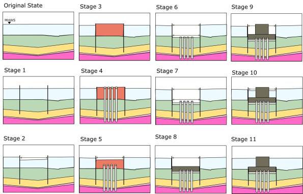
Option 2 – Cofferdam construction sequence.
The Importance of Understanding – Initial Sequence
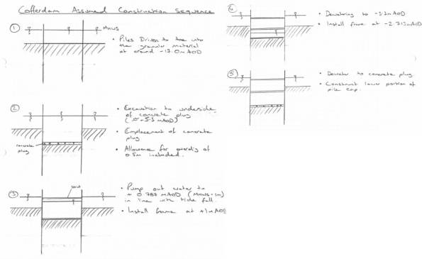
This is my initial construction sequence sketch. Sorry the sketches don’t want to embed in the document.
The Importance of Understanding
John Moran and the SI can be feeling justifiably smug right now. During both COFFERDAM and SOFT BOTTOM JM continual told us to understand the construction sequence or method statement of what we were doing before embarking on calculations. DB frequently told and re-told of how he would first spend time drawing stuff for design exercised before calculations.
I mentioned my encounter with bridge abutment design a little while ago where I picked up a slight error in my calculations in time when I realised the maximum retained height of a wall was in the temporary case during a road excavation. My point at the time was by knowing how things are actually built I didn’t publish erroneous calculations and felt quite good about my contribution, assuming that an engineer with less construction experience wouldn’t have picked it up. But my point should have been a lesson learnt, if I had thought about (and yes sketched) the construction sequence I would have picked up the issue even sooner and saved time.
I’ve previously mentioned the Barrow Bridge Tender which is a cable stayed bridge of around 1km in total length. On Monday I was tasked to answer questions on a couple of cofferdams that will be required to construct the foundations. The output is so the contractor can price an outline solution for tender purposes, the final design will fall to the temporary works designer for the project. Therefore the design needs to be economic enough to win the work but without spending too much time (and fee) on it, therefore not to Eurocode, old fashioned lumped factors of safety are the order of the day so detailed design might squeeze some savings.
One of the cofferdams will be mid-river (within the tidal range which can be used as a benefit when pumping out). The questions just wanted to know sizes of walings, props, sheets and likely toe depths. The really simplistic solution (though I don’t think even a true idiot would do this) would be to consider the whole thing wished in place props at the varying heights to ratios according to ‘h’ and produce that as the answer. This would be extremely wrong. A more sophisticated solution might be to consider the construction stages and check at each, again placing props at the recommended ratios of ‘h’. However it’s only when you consider what you’re making the cofferdam (Moran, 2012, his office with a disappointed Dad look) for that you realise that props need to accommodate the construction of the 3 metre deep pile cap and so props in the bottom of the hole are silly. It is easiest to reach all these conclusions with a pencil and a sheet of paper (Blow, 2012, tea and toast during misty eyed reminiscence). So having no idea how to construct an inter-tidal cofferdam with ‘I told you so’ echoing in stereo in my ears I picked up a pencil and sketched.
I started with the assumption that the piling and excavations would be conducted from a barge/jack up. The result is shown below.
The WALLAP analysis could then be run building each of these construction stages into the sequence. This would give me maximum BMs and SF in the sheets, and axial loads in the props. The software also gives the point at which the FOS is at a minimum which is after the water is pumped out prior to installation of the second frame so I can highlight it to the contractor. Feeling pretty please with myself I skipped along to a meeting on my own into the den of the bridges (a soul less place with engineers stacked tighter than baked beans in Tesco, I even spotted one asleep at his desk!).
My smugness was shortlived. The last time I talked about construction stages I missed the lesson, this time I didn’t. I can guess what I think might happen but the contractor has a very different plan, well 2 different plans in fact and he wants each of them sized. So this time I’ve drawn up the sketches for both options (Powerpoint beats pencils) and am seeking agreement on the sequence before doing any more numbers.
So JM and DB feel free to use me as the example of a PET student who though he knew better and Phase 1 really think about how things get built before you design them. I don’t know how relevant this is to building structures, I think it’s a little more subtle for example on site we couldn’t store a pallet of plasterboard on the floors because the design loadings were so small, they had to be split before storage.
This whole episode does again reflect on the difficulties of managing the design office environment, I was put on an element of the Barrow Bridge permanent design 4 weeks ago because there was nobody else, the Design Engineer working above me has had to return to site for 5 weeks on another bridge crossing (New Forth Crossing) and so I have become the only geotech bloke working on it. So when the extra work came in it was me to carry on, the design brief was given to me in isolation and the first chance to discuss it was during the meeting with the bridges team. Once again the matrix structure fails because people are given work because they are available. In reality there should have been yesterday’s meeting before I embarked on more detailed design, or perhaps I should have chased bridges for an outline sequence of construction?
I Feel Dirty
Today I genuinely enjoyed the construction of a spreadsheet, this is probably the day I’ve enjoyed more than any other since I’ve been here at Ramboll.
The Problem
We are part of a team tendering for a new large 1 km ish bridge over a river on my mudstone. I have been asked to look at the West Tower which is a spread foundation on the mudstone that is currently sloping quite severely and has a minor road at the top of that slope. The mudstone has discontinuities although orientations aren’t known. I was asked to identify whether there are any orientations that are particularly dangerous to the foundation.
Direction
Initially I was told to us Slope/W which is a simple program that can check large numbers of slip surfaces on a slope in a short time and come out with the least safe. In order to model the rock with discontinuities I was advised to model the discontinuities as regions with weaker parameters to encourage failure along these lines. It all made sense so I started learning Slope/W and built a model.
Issues
After running a few iterations of the model and speaking to the person who first tasked me it became obvious that things weren’t so clear cut. The model didn’t seem sensitive to the properties of the discontinuities, I even gave them the friction angle of ice cream and it still didn’t fail along them. Going back to original instruction revealed that she didn’t necessarily know how to get it to work, or even what the answer might look like (I can hear the Orator as I type if you don’t know the answer don’t use a program! I would be fairly unemployable right now if I stuck to that advice). She then promptly buggered off and after a day or two of wrestling with stupid answers spoke to the Director who had tasked the other engineer, he was equally confused but gave me a book on Foundation on Rock (along with a quip about when he was looking for it on Amazon all that kept coming up was music related, hilarious).
Stability of a wedge
The book was quite useful and gave examples of calculating the stability of a wedge based on certain soil parameters and geometries of rock and loadings. Because we didn’t really know the orientation of the cracks and that my brief was kind of a what if analysis I decided to stick it all into excel and see if I could make it work. This is why I feel dirty, I had to design the spreadsheet on paper to make sure I got all the variables, lots of coordinate geometry and learning to use ‘data tables’ with 2 variables later I churn out a table that will autocalculate the lowest factor of safety depending on crack angle and the point at which is intercepts the front of the slope. I can then fiddle with discontinuity parameters such as friction angle or rock unit weight or applied load and see how it changes the FOS. Next week I will interrogate a true expert on Slope/W to see if they can get better answers on the problem.
What have I learnt?
- Software can be limited – There were issued modelling the surcharge in Slope/W because it was below the level of the ground so I had to model a rock with a unit weight of 2200 kN/m3
- Books are useful
- Clear briefing is a skill that isn’t necessarily easy to find in an office, this relates to other stuff I’ve put on here over the last month or so that designers don’t get the opportunity to really manage, I’ve just had things thrown at me a couple of times and been expected to get on with it with little to no brief
Other recent lessons
- People will just assume you can read your mind, or they don’t know what they really want when the task you. An individual from another office working in structures wanted some pile group modelling done but didn’t explain how he wanted the output so the work took twice as long as necessary
- Geotechnics is about experience and experience, knowing where to look for the answers and best guesses are the currency. We are looking at doing an extension to a quay wall in a dock basin that can’t be drained and need to know what angle the mudstone can’t be excavated to and remain stable, the answer is ‘who knows? But our best guess is ….’
- When you tell people what you’re doing and that you’re going to CPR in Jul they all reply sceptically ‘That’s a bit fast isn’t it?’ they are promptly silenced when politely informed that the Army allows you to cover all the DOs they can’t in a design role. As an illustration a Resource Leader (read just below executive board level) gave a Business Update presentation the other day and I have genuinely seen Sappers do a better job.
Useful? Or am I a dinosaur?
In an attempt to get back on subject and make my blog sound less like an internal monologue that has spilled out into the public realm.
As DII (at least the last time I looked) is stuck in the Office dark ages I don’t think many will have really used some of this stuff, but you RSME issued computers, your work computers and probably any personal copies of Office are probably more up to date so this might be useful.
The ‘References’ tab on current versions of Word seems to be particularly useful and I wish I’d found it earlier.
References. I’ve been playing with it recently and it allows you to enter your references in a central location and then cite them in the main body of the document with a simple click of the mouse and seemingly to Havard standards! It will then auto-generate a references list wherever you want to put it in the document in the correct format.
Captions. Using the ‘Insert Caption’ function you can tell Word whether you’re annotating a Figure or a Table and it will auto number them, removing the problem of manually re-numbering if you decide to add another photo at the beginning of the document. Word will then auto-generate a list of Figures and Tables for you and give it the correct page number.
Cross-referencing. Should you need to refer to Figure X in your main body of the document you can do this using the ‘Cross-reference’ option it works for paragraphs too, it will then know to look in the right place. I don’t think this auto-updates BUT when it comes to finishing the document it seems that you can just right click on the entry in the main body and ‘update field’ it will then refresh the para or figure number for you.
I don’t know if I’ve just been a member of the slow reading class here and you’re all well aware of this or if everyone else has wasted time cross-referencing documents and manually generating contents list. If it’s the latter then hopefully this will make life easier for you all.
What Colour is My Parachute or…. Do I have ADD?
I found a document today that says the typical noise level for a quiet office or library is 40 dBA. I tested this figure against the actual value in my office. The mean value in the office was 36.4 dBA which gives you an idea of what it’s like on a daily basis, this absence of noise leaves me alone with the thoughts that rattle around in my head. I’m sure that those of you that know me are thinking they are cynical, overly critical ones and ones about the geeks I’m surrounded by that make me laugh. In truth it’s probably best that conversation isn’t common here; I referred to myself as a retard yesterday which resulted in a few shocked expressions, the only person I can speak to normally here is the ex-Garrison Engineer that has just turned up on the project management team.
Anyway the thoughts that I’m left with have been fairly neutral as I watch me excel spreadsheet countdown the days until a return to normality. Fine ladies and gentlemen of the Royal Engineers are not designed to sit in an office environment like this but those of us on Phase 3 are doing our best to conform. For me this has involved writing 2 reports longer than TMRs, doing design and cat 2 checks. I usually have a number of things hanging around that need picking up and dropping at random whilst waiting for someone else to do something with it. What I have found is that things hang around for a really long time and then suddenly reach the top of someone else’s to do list before the deadline, kind of like trotting along with the fat blokes on a PFA only to realise you’ve got 15 seconds to cover the final 100 metres, or a reverse hurry up and wait arrangement. This REALLY doesn’t suit me, throughout our time in industry it’s natural to consider whether you would want this job, or someone else’s job, and could spend the remainder of your working life doing it, often my answer has been no. I found myself getting a little bored of site although the human capacity for stupidity kept that fresh but now I’m bored beyond belief (even more bored than TELIC when we’d eat huge amounts of sweaty cheese just before bed just to make our dreams interesting). There is a variety of project work to do but it all goes so slowly I find it hard to be stimulated after the initial reading in and then reaching the first obstacle where I’m completely reliant on other depts to move it along. Continually reviewing the same thing over and over with different partial factors is purgatory.
Why is this?
Has a career characterised by office firefighting, exercise planning where I was mostly solely responsible for output and the BGHQ 24 hour planning cycles of CAST and BATUS left me permanently scarred and unable to concentrate on anything longer than a few days? Have I been condemned to trying to find the employment equivalent of University Challenge where I get asked no more than 3 questions per subject? Do I have Army induced ADD? The answer must be no, I’m still writing AERs and TMRs far better than I thought I would manage, I’ve done other things that have had long lead ins so what is it? I can only think that working in an office quieter than the average library is part of the problem. But I think the biggest problem is a lack of complexity or at least the right type of complexity, Nick Fielding will laugh at the concept of ‘enjoying the complexity’ but genuinely I think this is the problem.
So that was an insight to what I have to listen to on a daily basis, if I make it to Jul without screaming it will be an achievement.
Roles and Responsibility?
Below are a few observations of my time in the design office so far, a continued criticism from the Orator is that there’s not enough reflection in my work so I’m trying to plug that gap slightly, this started off slightly more formal then it ended up however with a little pruning it will end up in AER 5. The final point is an observation on where geotechnics fit in to the grand picture, mainly at the bottom (pun intended). Sorry no pictures today, my desk is mainly looking dull.
I have been designated a Graduate Geotechnical Engineer, the positions more senior to me are:
Design Engineer – a number of years design experience, 3 in section.
Senior Engineer – A chartered engineer or geologist with commensurate experience, 2 in section.
Principal Engineer – An experienced Senior Engineer coordinating larger projects incorporating a number of junior engineers. 2 in section.
Associate, Project Director, Technical Director – Individuals with significant experience and typically dealing with checking, budgeting and oversight rather than design.
My presence at Ramboll is for a very specific purpose, to learn the more technical aspects of the civil engineering profession. My willingness to assume responsibility and ability to organise have been proven elsewhere in my career; by contrast for a junior engineer searching for competencies outside of their immediate day job opportunities would be very limited. Comparing this environment to that of a site based graduate working for a contractor the points I would note are:
- Responsibility. Both roles lack responsibility however the day to day tasks of a contractor are mundane and frequently just involve box ticking type inspections, there is very little thought beyond the consideration of safety infractions of particular operations. A contractor learns more through conversation with and observation of their line managers, from my time with Osborne there was not much of a mentoring type relationship. A designer by contrast is responsible for their design and must recognise the limits of their own competence, a designer learns by doing whilst mentored by a more senior engineer.
- Understanding of CDM. CDM is a fundamental aspect of construction in the UK, it shapes every stage of design and delivery. Much of the work seems to be completed early in a design, certainly from my experience as a contractor CDM was something that was done to you and to hear it’s title in conversation was a rarity. A contractor does get to understand buildability fairly quickly a benefit of being exposed to tradesmen from an early career stage. If you accept that much of CDM is completed in the early stages then it must be the designer that is doing it. This means a relatively junior engineer who has probably not been exposed to site work and is basing their work on university designs where things are wished in place. I would pride myself on being able to think through a problem and how it fits together in time and space and have found myself picking up aspects of design too late. An example has been designing the retained height of a wall to finished road level forgetting that a road needs to be dug out before it can be constructed therefore increasing the retained height of the wall in the temporary condition. How are junior designers expected to pick things like this up? The lesson I learn is that even though CDM felt like it was all complete by the time it hit site the truth is: Buildability needs looking at long before the on site operation begins. Unfortunately the reality is this is next to impossible due to time constraints on site.
- Application of knowledge. On site application of knowledge is rare and extends more to techniques rather than principles, the techniques are normally learnt from a more experienced manager or perhaps even a tradesman on site. The graduate contractor is quite possibly surrounded by managers of various backgrounds and depending on the company is probably in the minority as a civil engineering graduate. As a result they see many of their colleagues and line managers avoiding true engineering. It is quite natural for a graduate contractor to become relatively blind to technical issues or even shy away from them altogether. I certainly felt a couple of times like I had a bit too much of the classroom about me however soon realised this was wrong as others were blindly skipping along telling people to put their glasses on whilst ignoring bigger issues. Possibly this is natural due to the delineation of design responsibility and risk, why try and solve someone else’s problem? Actually it’s not a in contracting company’s interest to get involved as is muddies the waters when it comes to claim time.
- Management of people. A design engineer gets no exposure to managing people, reading the ‘Successful Chartered Professional Reviews’ book combined with the ICE DOs management and coordination is a key attribute of a Chartered Engineer. Whilst I acknowledge that the reviewers are asking the question ‘would this person make the right decisions if they were placed in the appropriate appointment?’ rather than ‘has this person made the decisions expected of a CEng?’ it must be hard for a designer to demonstrate that the answer to the former question is yes. This lack of management could possibly extend for the first 10 – 20 years of their career depending on how quickly they rise however ultimately some of these people must eventually become team directors and perhaps even board members. Times on site as residential engineers or secondments to contracting companies can close some of the gaps but possibly not fully. This is perhaps where matrix structures fall down and a more project based organisation has the potential to develop better future managers and leaders as there would be a greater exposure to project managers (who should be good people managers) doing their jobs. The opposite is of course true for a contractor, they are exposed to a huge variety of people from an early stage. Early on at the lower end of the spectrum they have to manage, cajole, bribe and blackmail them into doing what is required on site. As they become more senior they then have to ‘manage’ their own line managers by managing expectations and diplomatically telling them that some ideas are stupid.
-
Uniqueness of geotechnics. I am coming to the conclusion that Geotechnics isn’t where the cool kids hang out. We all know that work in the ground carries a huge amount of risk and that geotechnical engineers are often the key to reducing that risk to acceptable levels. However the geotechnical section always seems subordinate to everyone, for example the Associate in my section regularly seems to be picked on by an Associate from highways; the Senior engineer who is borderline special gets picked on by his equal from Building Structures. I don’t quite get it, I know our part of whatever is built is buried or hidden away and our work effectively becomes the enabling work but it’s always pretty important, and always on the critical path, it’s like we’re the RLC of the design world. For example highways need a large number of gantries designed for roads, the loads never changed, the kit that gets hung on them rarely changes the only different bit is the ground underneath and yet we are definitely working to them rather than the other way around.
I don’t just complain about civilians…
I do some work too….
Actually writing down stuff that sounds a bit clever seems to be de rigueur at the moment so I thought I better make a bit of an effort, I can’t be flippant forever and RF is right CPR is somewhere on the horizon. The bridge foundation I’ve been working in in the final stages but it’s not been on my desk for a week or so. Much of last week was spent preparing a basement impact assessment for a domestic property in Camden, quite interesting (in an engineering sense) and not too many numbers thankfully, that’s now with one of the environmental guys to do the flood risk assessment and awaiting RFIs to be returned from the developer. Something that’s been hanging around in the background for a while has been a gone wrong wind farm, thankfully not gone wrong because of us but Ramboll have been called in to provide expert witness services, I think we could be prosecuted under the trade description act as I’m the only one from geotechnics working on it currently and I can’t claim to be an ‘expert’. The initial request was to do with the actual foundations of the turbines themselves there were doubts raised during the checking process (which was complete after construction commenced) this didn’t progress very quickly initially although it has since landed back on my desk, thankfully with the help of Repute an uber pile calculation programme and the structures modelling software I’ve not had to wrestle with ‘piling in weak rock’ as the piles go down through peat and glacial tills to Sherwood Sandstone underneath. The second part of the contract was to conduct a check on the crane foundations that were constructed for the build phase. In short the foundations were subject to a litany of design problems and the tender submission was woefully inadequate although the tender drawing alluded to this the design and build contractor never really developed the solution and the ‘typical solution’ became the ‘for construction’ solution and the contractor progressed without the stipulated written consent from the turbine manufacturer. That’s the short version, getting this far along has required an awful lot of reading and cross referencing of documents and has felt a little like doing another TMR. Below is the whole report that I have prepared so far on the initial design and will start on the remedial works tomorrow. I won’t blame you if you don’t read it.
1. Introduction
1.1. Background
Ramboll have been engaged as an expert witness commissioned by Hill Dickinson on behalf of BSW Consulting to carry prepare a preliminary report in relation to the design of the crane platforms used to erect the wind turbines at Orchard End Wind Farm.
1.2. Qualification of Authors
The qualifications of the authors of this report are summarised below:
Rich Phillips, Graduate Engineer, BEng
2. description of project
2.1. Location
The site is located at North Wood’s Hill Farm in Wyre Borough, Lancashire. The area is arable land which is drained by a number of ditches discharging into the surface water channel known as the Momen Gutter.
2.2. Wind Farm Development
To date 2 wind turbines and associated support infrastructure, control buildings and access routes have been constructed. The client for the development was REG Windpower Orchard End Ltd, part of the REG Windpower Ltd group with Askam Construction Ltd appointed as the design and build contractor. The initial tender designs for the scheme were provide by BSW Consulting Exeter Ltd, BSW were later appointed by Askam although never formally novated.
2.3. Issue
BSW’s design responsibilities included the working platforms used by the turbine provider, Vestas, to operate the cranes used to erect the turbines. In support of the design of the scheme they were provided the Ground Investigation Report (GIR) supplied by Ground Investigation (Wales) Ltd who had been engaged by REG to provide the necessary geotechnical information for the design of the scheme.
In Dec 12 it became clear that remedial works were required on the crane pads, BSW provided a design and remediation began in Mar 13. During the erection of Turbine 1 the crane outrigger suffered excessive deflection and the work was aborted. As a result of this a piled solution was pursued at the request of Askam.
3. References
The following sources of information have been used in this assessment:
- Email Sarah Naylor/Paul Jackson, dated 24 Dec 13, Ref SJN.940401.6129.
- Geo-Environmental Site Assessment Report, dated Jun 11, Ground Investigation (Wales) Ltd.
- BSW’s privileged report (we have been instructed to treat this as sensitive).
- Application Suggestion for Orchard End Wind Farm from Tensar International Ltd supplied to BSW, dated 7 Dec 2011.
- Working Platforms for Tracked Plant, BR 470, 2004, Building Research Establishment.
- BSW design drawings (Tender):
- Site Construction Access Track Layout, Sheets 3 & 4, dated Dec 11.
- Road, Crane Pad and Hardstand Specifications for Vestas Turbines V80-V90-1.8/2.0MW V82-1.65MW and V90-3.0MW, dated 9 Mar 10, Ref 0002-0277 V03
4. pre-design information
4.1. Ground Investigation
The GI conducted 2 No boreholes located in the centre of the turbine foundations with a larger number of machine excavated trial pits completed under the foundations and along the proposed access track alignment. Soil strength parameters were determined through the use of:
- SPT.
- Shear vane tests.
- In-situ CBR correlation tests.
- Laboratory testing including tri-axial, oedometer, particular grading and Atterberg tests.
The outline sequence of strata and design parameters found in the borehole under Turbine 1 are detailed in Table 4.1.
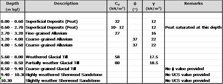
Table 4.1. Sequence of strata encountered in Borehole 1.
4.2. Qualitative Assessment
Section 6 of the GIR provides assessments and recommendations for each element of the scheme and in particular highlights the geotechnical hazards on site; the first hazard detailed in the report is the presence of the low strength deposits of peat and alluvium. The key assessments and recommendations relevant to the Turbine 1 crane pad made in Section 6 are as follows:
- Water was encountered in the low lying areas during excavation between 0.6m and 0.9m below ground level. (Ref 6.4.5)
- ‘Hand vane tests conducted within the upper Peat horizon indicted an undrained cohesion of typically 30 kN/m2, reducing to around 10 – 20 kN/m2 within the saturated zone below around 0.6m depth. Values of undrained cohesion reduced further within (sic) increasing depth, to values as low as 6 – 8 kN/m2. The values….indicate that strata of very low-strength and high compressibility occur beneath the loaded zone of the crane pads.’
- CBR correlations across the site frequently returned values below 1%.
- The crane pads must not be found on the Peat, instead the full thickness must be excavated in order to reach the material below.
- The recommended figure for acceptable bearing pressure on the Fine-grained Alluvium was 35 kN/m2 if this loading could not be achieved then excavation to the Coarse-grained Alluvium should take place with a maximum applied pressure of 50 kN/m2.
4.3. Summary
The assessed soil design parameters combined with the qualitative assessment of GI (Wales) indicate the presence of a slightly stronger ‘crust’ in the top layer of the Peat above the saturated zone. The material below the crust is significantly weaker and unpredictable, a foundation design might be suitable for the upper layer but the pressures applied to the strata below might exceed the allowable bearing capacity.
5. Design approach
5.1. Design Loading
BSW based their initial calculations for the design loading on a public document published by Vestas (the turbine manufacturer). This document explicitly states:
‘This document is not sufficient in and of itself to construct…Crane Pads…and must be supplemented for each project and site before construction work commences….
The exact design of … Crane Pads… must be agreed with Vestas in writing prior to start of construction.’
This document stipulates the minimum bearing capacity of the crane pad must be 200 kN/m2 unfactored. It also states that ‘floating’ designs are unlikely to be acceptable. The document continues to establish the minimum physical dimensions of the crane pads.
5.2. Tensar Appointment
As part of the design development BSW employed Tensar Ltd to provide designs for the access tracks and crane pads. In support of this request elements of the GIR and the Vestas crane pad design document were provided to Tensar, archived email evidence of this has been provided by BSW. The sections of the two documents mentioned had significant sentences and values highlighted, specifically:
- CBR values quoted in the design report.
- The value of 200 kN/m2 as a design load for the crane pad.
[Crucially] The highlighting did not include:
- The recommendation to remove all the underlying peat.
- The very low undrained shear strengths of the Peat and Fine-grained Alluvium which provide a more representative value compared to CBRs.
- The fact that the 200 kN/m2 was unfactored (although this was later allowed for with a lumped factor of safety).
- ‘Floating’ designs are unlikely to be approved.
5.3. Tensar Solution
Tensar provided their Application Suggestion to BSW on 13 Dec 11. The document stresses that it is not a detailed design and that construction should not commence on the basis of it alone. In the main the document seemed aimed towards highlighting the potential reduction of construction effort, and therefore cost, with the incorporation of a geogrid.
The Tensar solution provided calculations based upon a CBR value of 1% which they have equated [by an unknown method] to an undrained shear strength of 24 kN/m2. The design utilises the TriAx geogrid and asserts that the load distribution will double as a result (Figure 5.1).
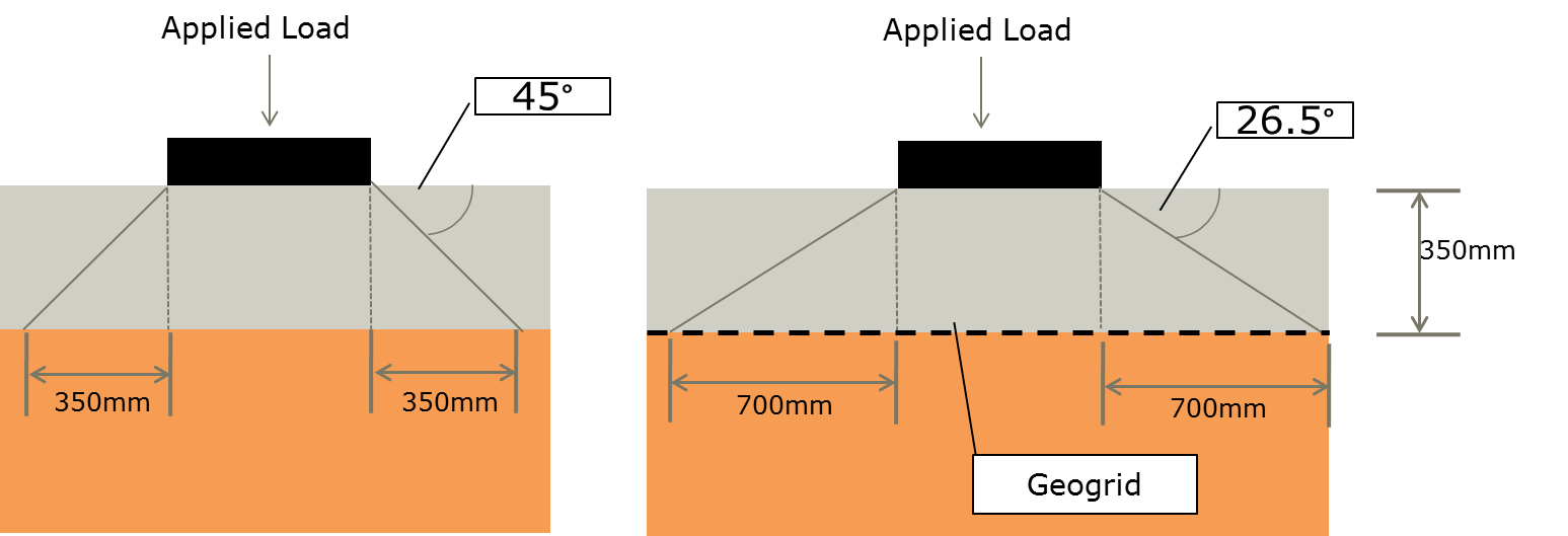
Figure 5.1. Tensar approach to load distribution.
The Tensar Application Suggestion states that for a 1 m2 area loaded with 200 kN a 350 mm thick road construction would distribute the load over an area of 2.89 m2 with a resulting applied bearing pressure of 69.20 kN/m2. In the case of the upper level of Peat this may have been acceptable but this neglects to allow for the very weak deposits in the saturated zone. [A quick use of Bousinesq would suggest that the underlying weak strata are over-loaded]
The proposed construction method involved laying the geogrid directly onto the top soil and existing vegetation and then building up the road. This would constitute a floating design and as such is unlikely to have been approved by Vestas. The ‘Crane Pas and Site Compound Construction Detail’ on the BSW design drawing would suggest excavation of 350mm of material, laying geogrid and then building the road up level to the existing ground level. The design drawings, marked ‘Tender’, include the note shown in Figure 5.2.
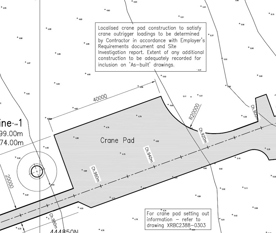
Figure 5.2. Note included on the tender drawings.
5.4. Summary
The outline design included on the tender drawings by BSW was not fit for purpose for the following reasons:
- The Tensar design was only an Application Suggestion requiring further detailed design prior to issuing for construction. The Application Suggested was not fit for purpose because:
- It was a floating construction and as such unlikely to be approved by Vestas. It seems that BSW modified the Tensar construction method to make it less like a floating road by excavating the road thickness into the Peat, this excavated through the stronger crust and therefore exacerbated the situation.
- Tensar conducted the design based upon tenuous CBR information correlated to undrained shear strength and failed to take into account the significantly weaker layers underneath the upper Peat.
- The design loading was based upon a minimum value found in the Vestas document which was clearly caveated to state that site specific loadings were required for detailed design.
- It ignored the recommendations of the GIR to remove all the Peat in order to provide a more reliable formation material.
BSW knew the above was only an initial design primarily because of the lack of a detail lift plan for the erection of the crane hence the clumsily worded note on the design drawing.
Askam had access to all the documentation available to BSW and as the design and build contractor hold ultimate responsibility for the design of the works. Without a written agreement from Vestas accepting the design of the crane pads, the requirement for which is clearly stated in the document referred to in this report, Askam should never have progressed with construction.
