Archive
Drafting complex 3D structures – 2 min read
Building 3D models of bridges with complex geometries is beyond anything I can do in Revit. With varying curvatures in up to three dimensions it can take the bridge drafters a while to build the 3D models.
To do this the drafting team use a visual programming language which plugs in to 3D modelling software. To me the programming looks extremely complex but on a basic level appears pretty intuitive. Using this they are able to model the bridges. Importantly it allows different drafters (in separate countries) to quickly understand and update the models.
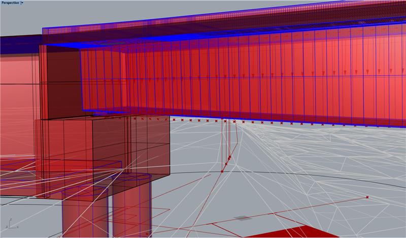
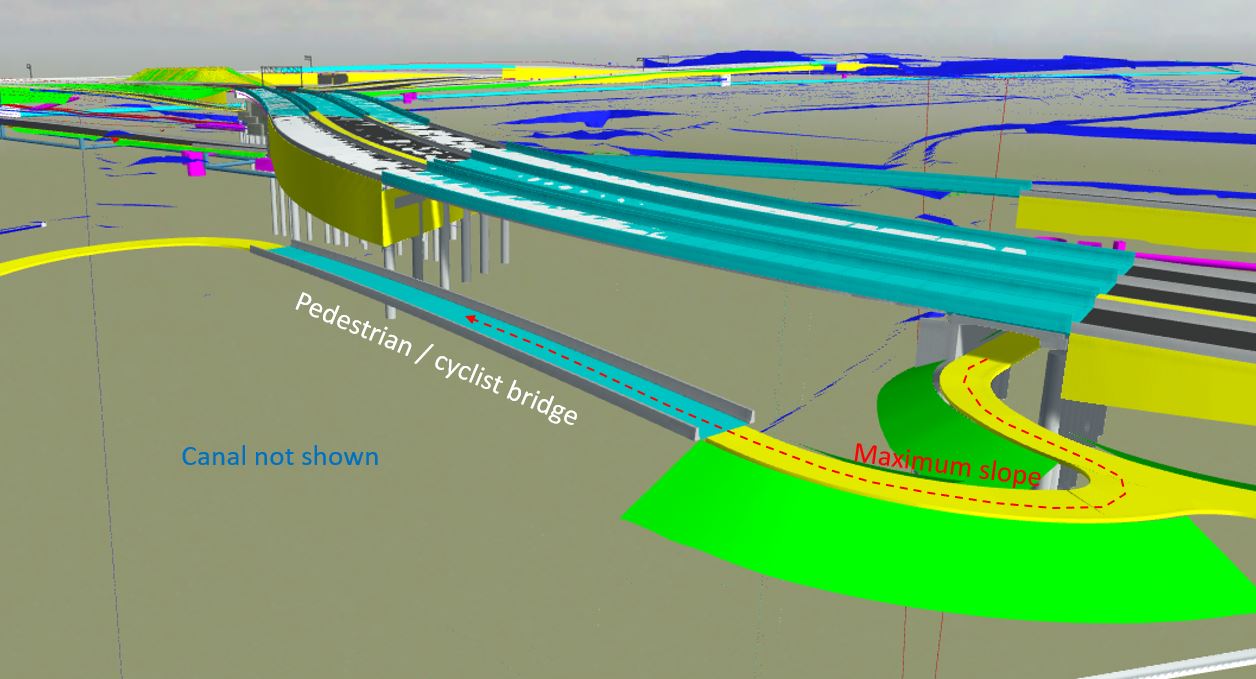
3D model of the bridge I have been working on. The soffit varies in a single dimension while the deck curvature varies in all three. 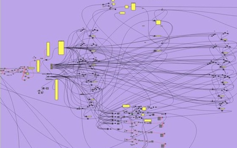
Screenshot of part of the visual programming language used by the drafting team to build a 3D model of the bridge. Software is Grasshopper. 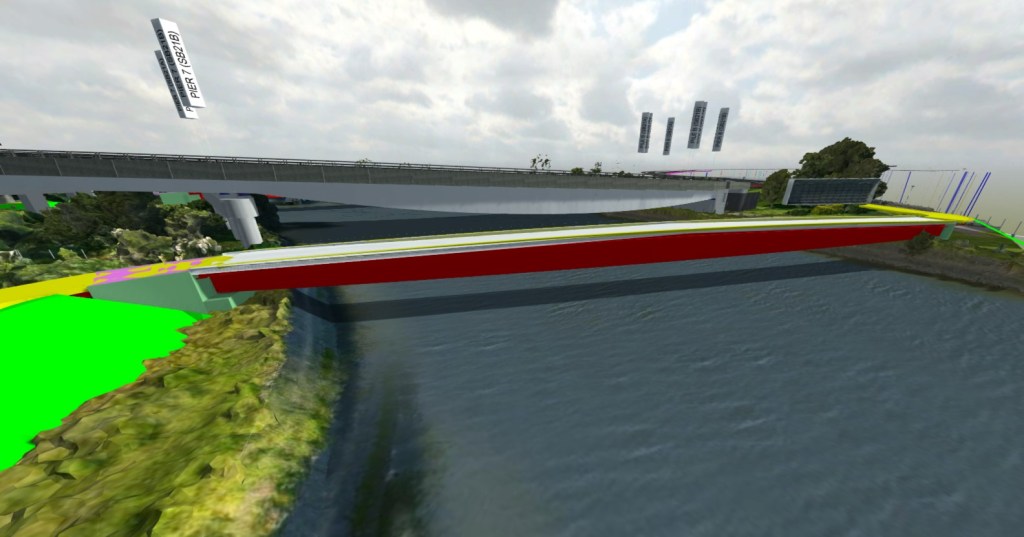
3D model imported into Revizto (BIM level 2)
The design consultant I have been attached to now exclusively use Revit on all building projects. However, the bridge team only use it on about half of the bridges with the other half being drafted in AutoCAD. Fundamentally though there isn’t much of a difference between the two. The Revit drafters use a DYNAMO visual programming language plugin while the AutoCAD drafters use Grasshopper 3D (visual programming language) and Rhino 3D (3D modelling software). With a lot of bridge drafting still done in 2D (cross bracing would take a long time to model in 3D) I can see why Revit has not been fully adopted. However, the bridge drafters believe that in 5-10 years they will be exclusively using Revit.
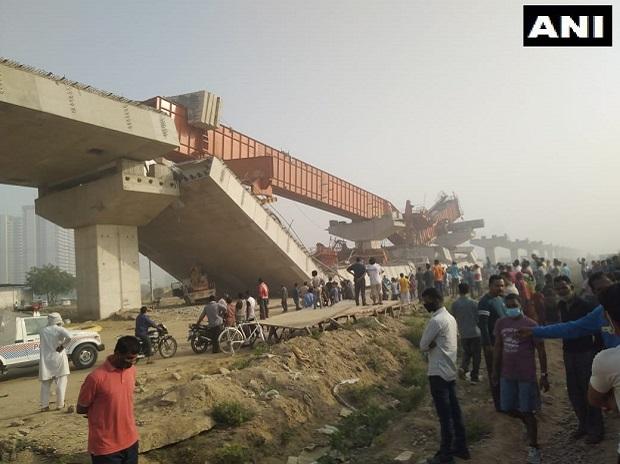
Bridge collapse New Delhi
Looks like a bridge collapsed in New Delhi over the weekend, no details on how or why it happened yet. I’m sure the details will be published in time but it is a reminder for those of us working in design offices that things like this happen. From the limited photos it isn’t clear if the failure was in the ground or with the temporary works.
Ex BRIDGE reshow
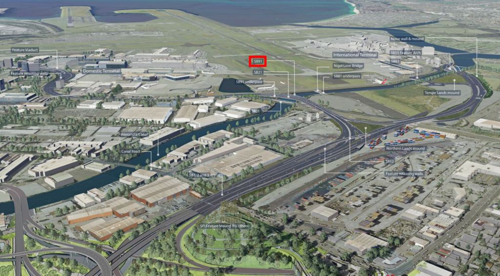
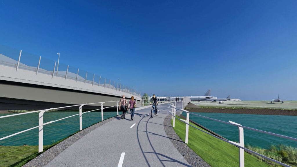
For my Phase 3 attachment I have moved to the Engineering Consultant BG&E and am working on a large road infrastructure project in Sydney. BG&E are designing the 13 bridges for the John Holland Seymour Whyte joint venture and I am leading on the pedestrian and cycle bridge over the canal to the north of the airport.
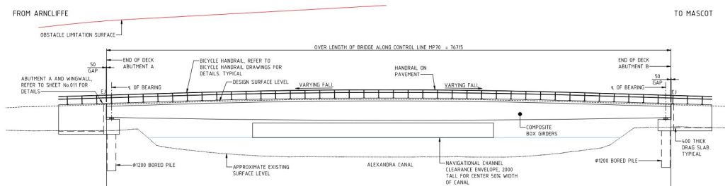
Spanning 75m it will be a steel concrete composite bridge with varying depth. The design interfaces with a few other design aspects and these have resulted in some very tight restrictions on the structure. Four key ones are:

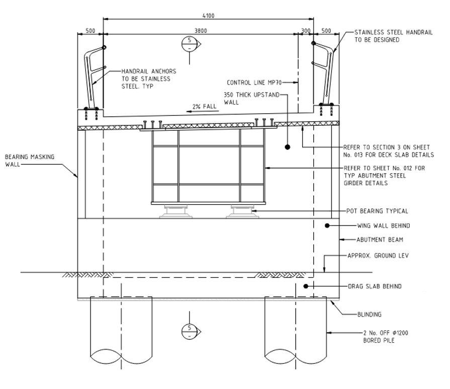
Deck height
The deck is limited by the slope of the path from the underpass of the planned adjacent bridge to the centre of the bridge and the sight distance over the span. This slope is set to the maximum that is allowed by the disability act in Australia. This limits the max height at the centre of the span.
Bridge soffit
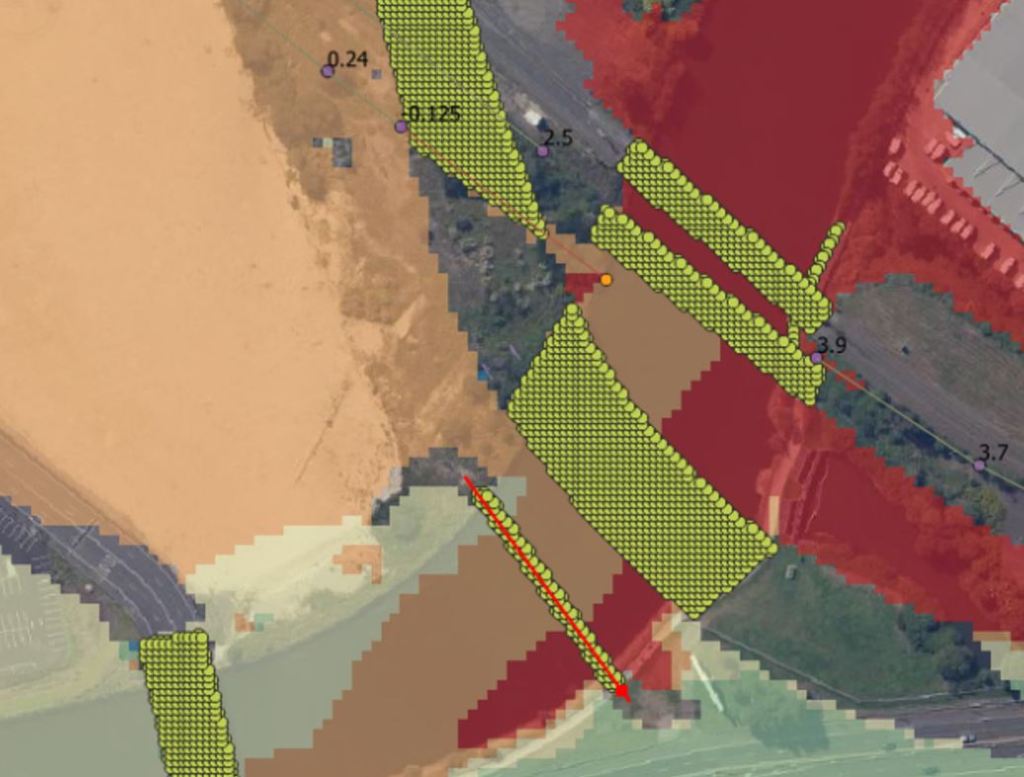
The underside of the bridge is limited by flood modelling. I assumed this would be set at 500 mm above the 1/100-year flood event as is stipulated in the contract. However, there is also a clause that the project cannot increase the predicted level of flooding at a substation 1.5km upstream during the Probable Maximum Flood (PMF).
The PMF is used to define the limit of flood prone land and has an annual exceedance probability of once in every 10,000 to 10,000,000 years. The issue is that the underside of one of the upstream bridges has already been set at the limit that causes an afflux at the substation, this means that the model is now very sensitive to reducing the height of my bridge.
The frustrating bit is that the substation will be flooded by 2 m during the PMF. The contract clause means this can’t increase to 2.01 m. I’m hoping sense prevails and this can be adjusted.

Alignment
This bridge was moved after tender submission and now the alignment is constrained by land ownership boundaries. When combined with the approach path radius it limits the angle at which the bridge crosses the canal. This pushes up the span to 75m.
Piers
Why no piers? This is because the canal is so heavily polluted form years of industrial use. Transport for New South Wales would rather pay for the bridges to span the canal, rather than deal with the risk of disturbing this pollution.
Impact
Because of all these factors the bridge has ended up with a span to depth ratio of 26 and about 130 tonnes of steel which has to be in one lift. My main concern is bridge dynamics as pedestrians are far more sensitive to bridge movements. Guess there could be a blog post in it…
Piling in
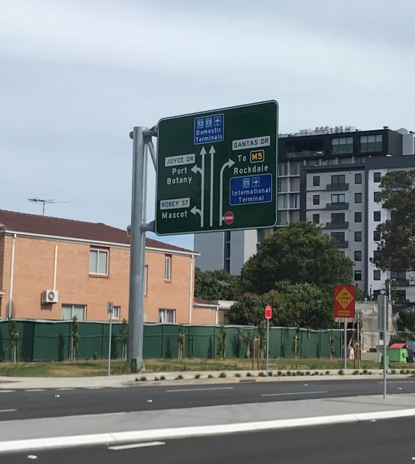
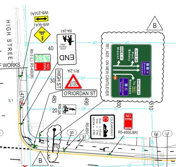
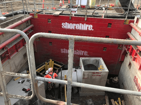
My project is a road widening in Sydney that requires a number of road signs. There are a significant number of small signs and three large ones which require piles. A number of sub-contractors tendered for elements of the work earlier this year but only one submitted a tender which included both the signs and piles. This was the deciding factor in the decision and the contract was awarded to them for approx. $500k.

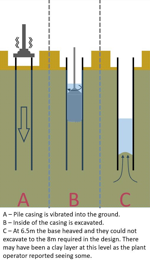
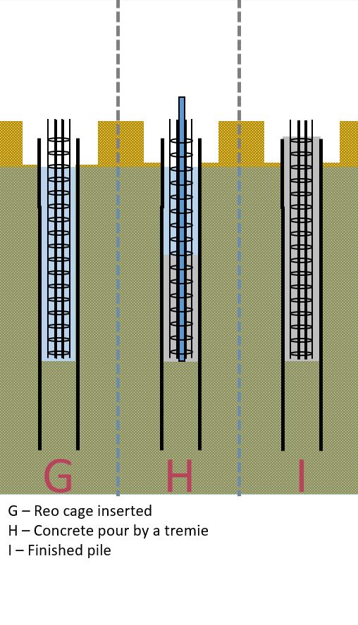
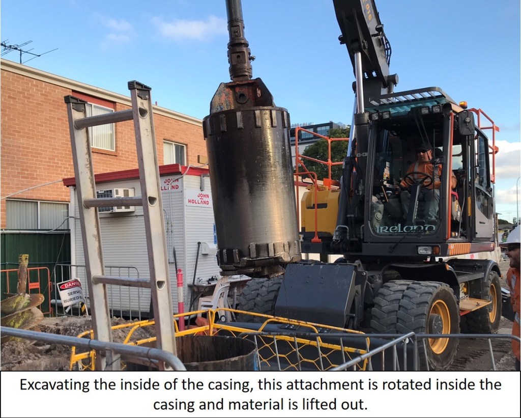
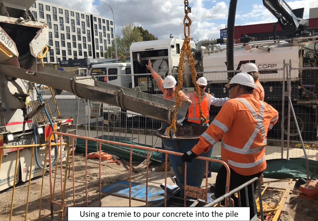
The sub-contractor selected is a sign structures specialist and they sub-contracted the piling work. As there are only a small number of piles they decided against CFA piles and instead opted to use a permanent casing, bore the piles and use a tremie to pour the concrete. The rational for this, I believe, was that the savings made in plant mobilisation outweighed the cost of the lost casing. The ground is medium to dense sand with a couple of clay layers with ground water a couple of meters below ground level.
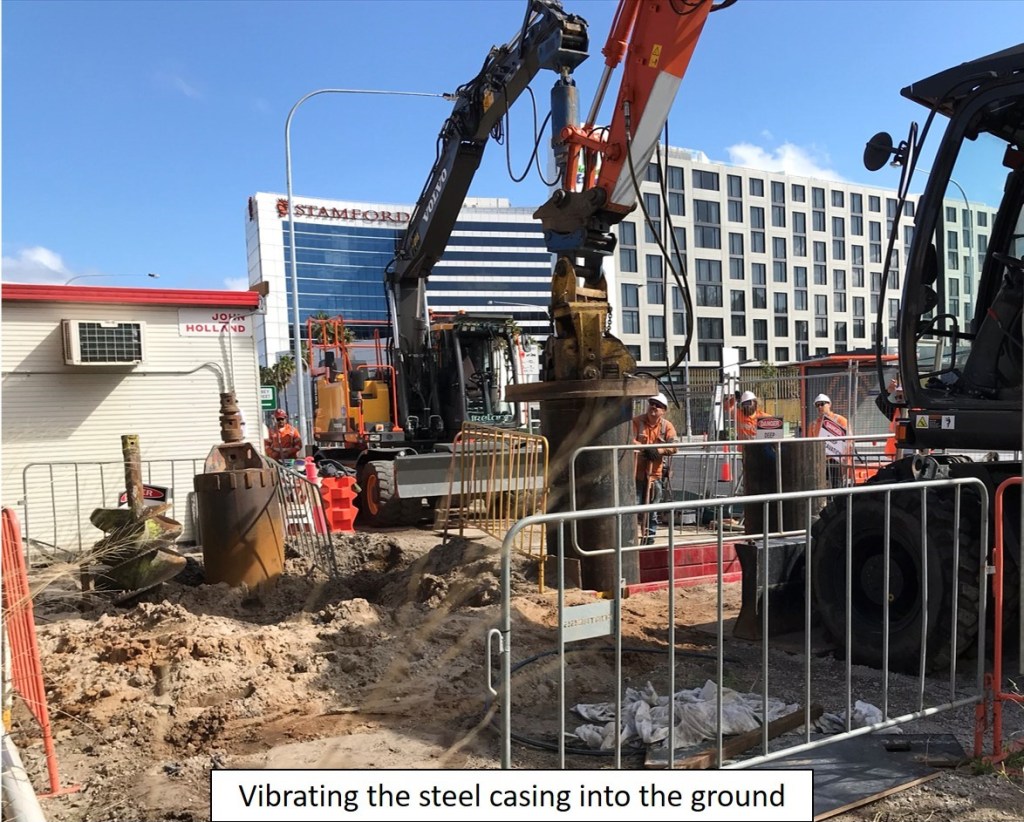
When piling for one of the signs (shown in the photo) the sub-contractor was unable to excavate to the design depth. What happened and photos are shown below:
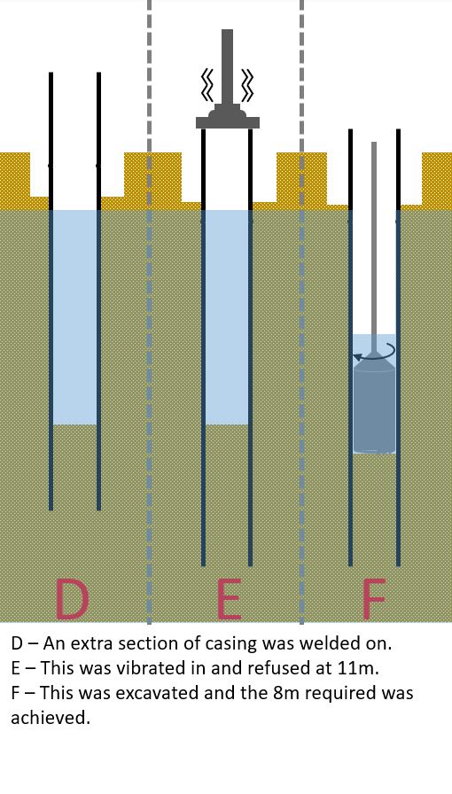

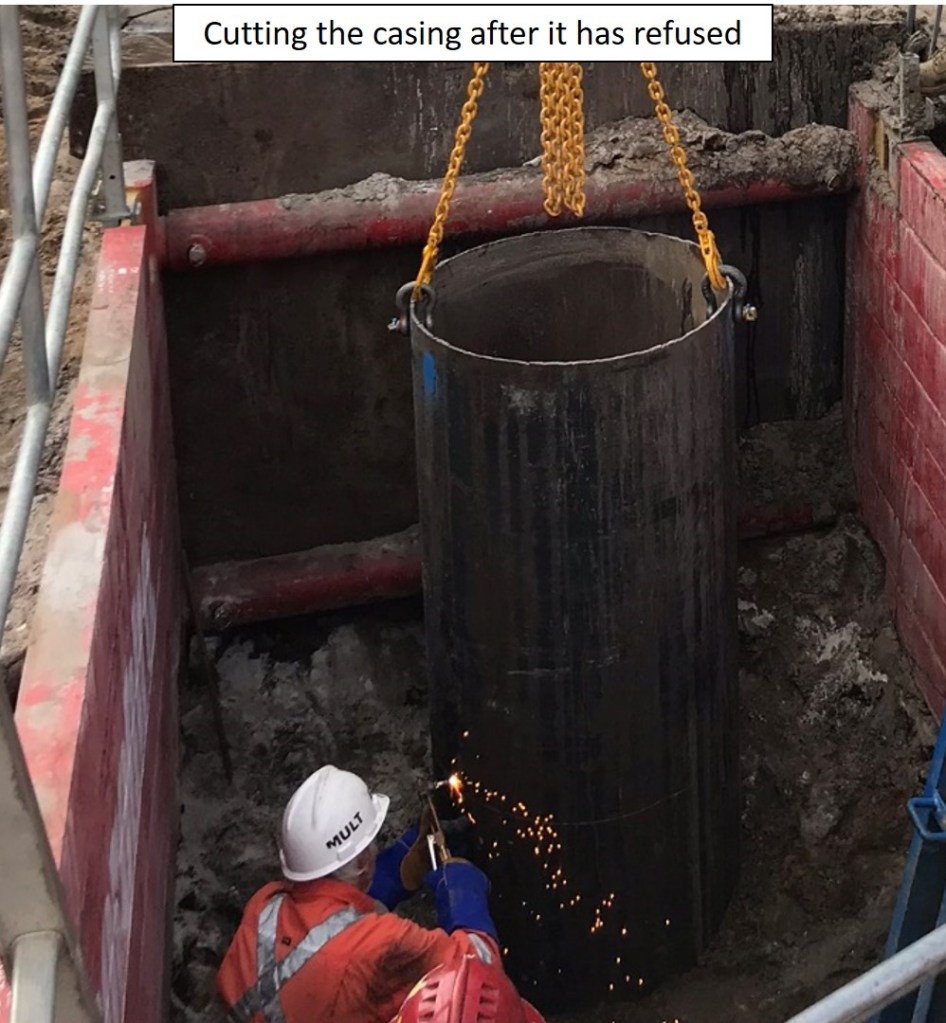

When the first excavation could not reach the depth required the sub-contractor claimed it was unknown ground conditions and wanted to put in a claim. Looking at the contract they had taken on this risk. However, as these signs are on the critical path and John Holland wants to complete this job as quickly as possible the sub-contractor was instructed to proceed. Discussing this with the contracts manager his take is that John Holland will probably end up paying some of the extra costs as they are very small ($3-5k) in relation to delay costs to the project.
We (John Holland) ended up having to supervise all the piling works as the sub-contractor was unable to. Most of these costs were back charged to the sub-contractor. The general feeling in the project team is that if they were to do this again a specialist piling company would have been selected.
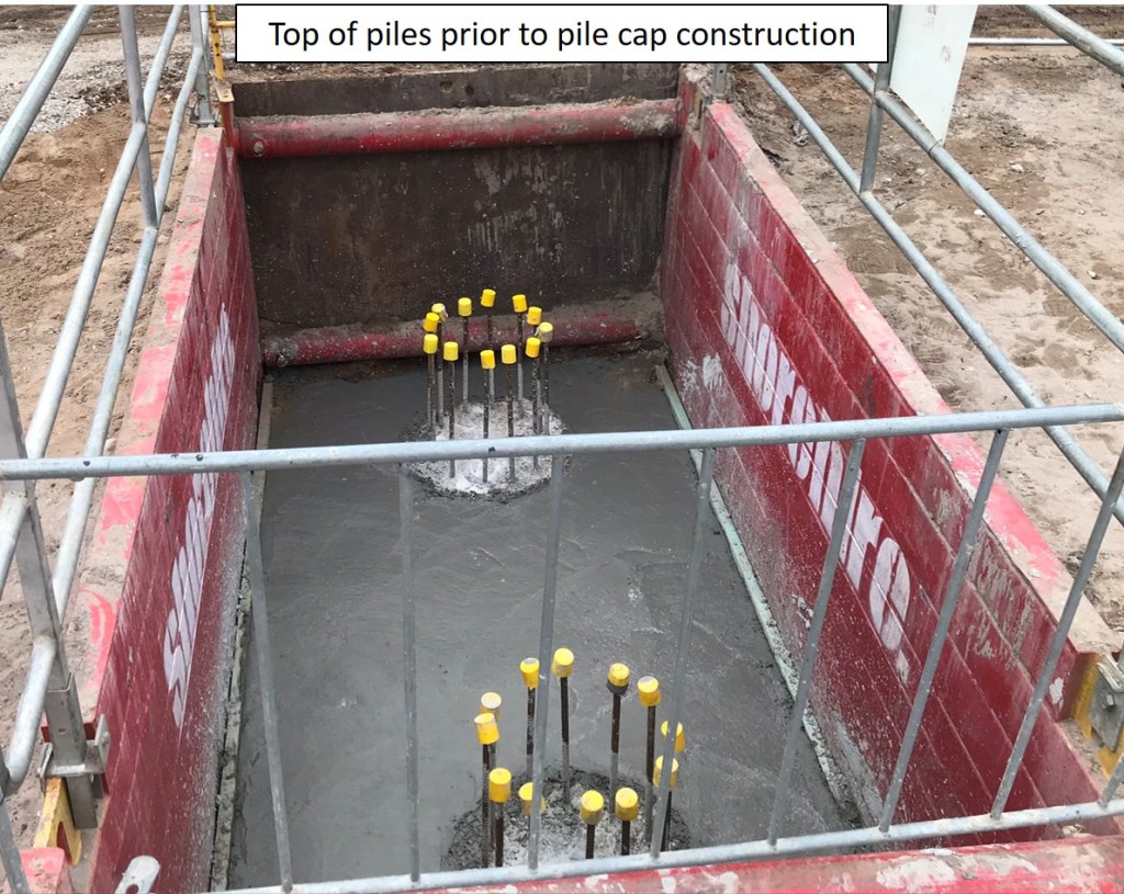
I estimate that the horizontal loads on these piles area around 4 times larger than the vertical loads. What has been built in my opinion is significantly over engineered as:
- The pile casings are now 35% deeper.
- The ground conditions are far more favourable than the medium dense sand allowed for in the design.
I feel that when the pile could not be excavated to the design depth there may have been an opportunity to get a revised design approved with a deeper pile casing and shallower concrete infill. However, the focus is on constructing as per the client’s design and getting this design approved would have taken far longer than just getting the sub-contractor to continue and project delays costs were far more significant.
Low flying aircraft
Part of my project’s scope is covering the defects from John Holland’s previous project next to Sydney Airport. The liability period ends next month so Transport for New South Wales (the client) are pushing a few through before time runs out.
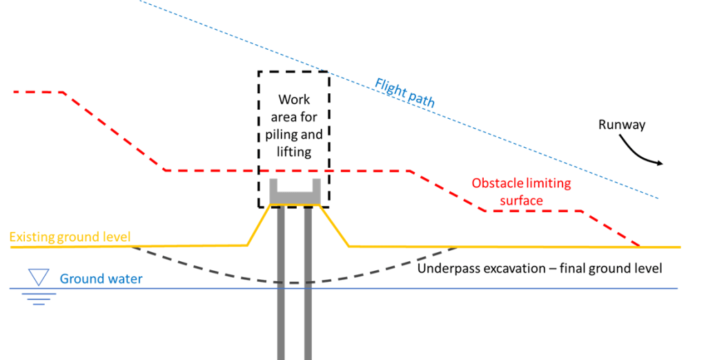
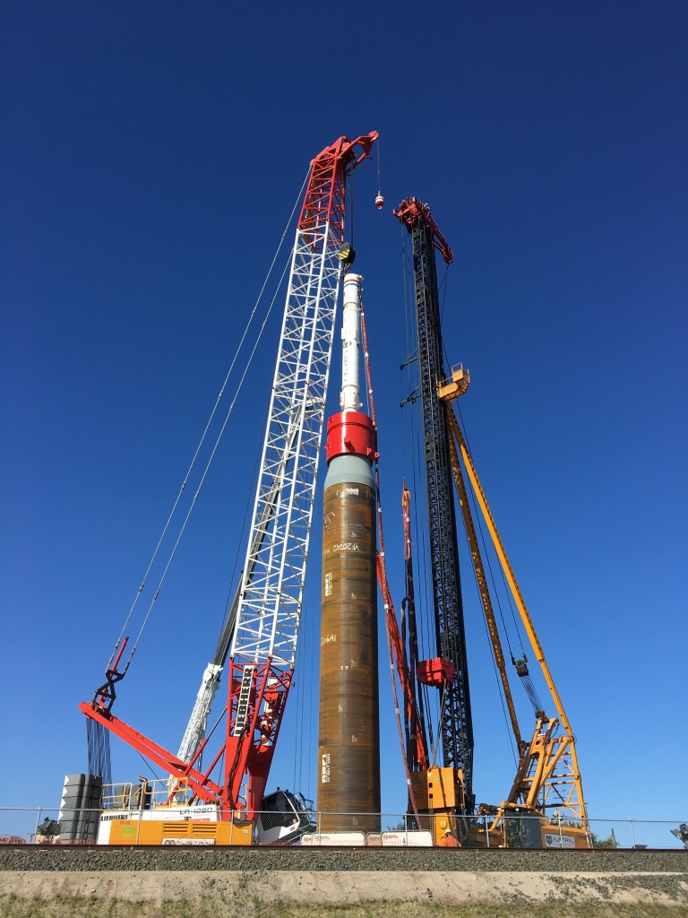
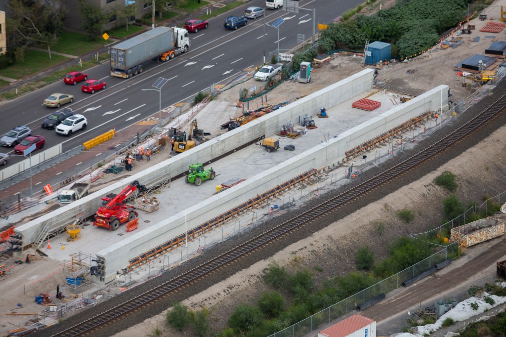
An element of this project was constructing a railway bridge in the airport’s flight path. I have included a few photos from the project to show the staging design and significant construction restrictions.
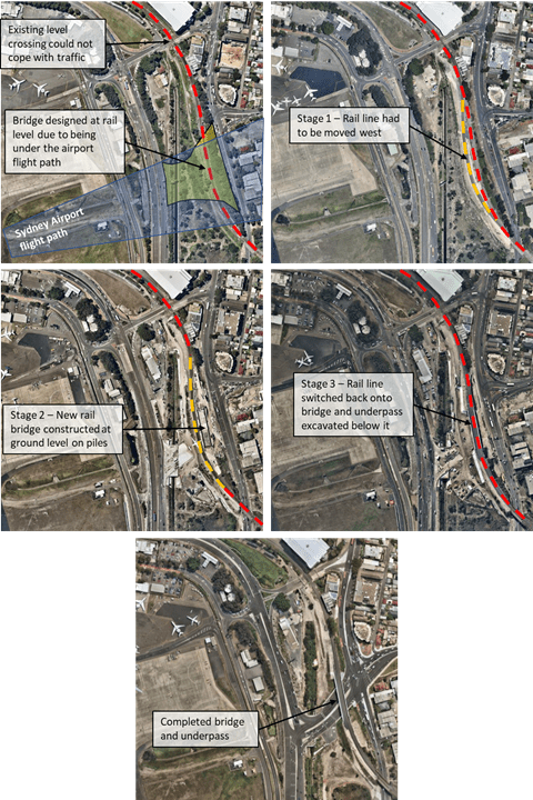
If this was being done now it would be much easier… I rarely see any aircraft.
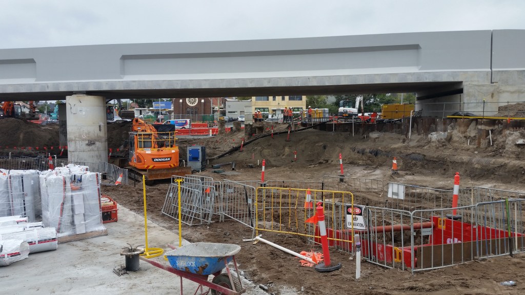
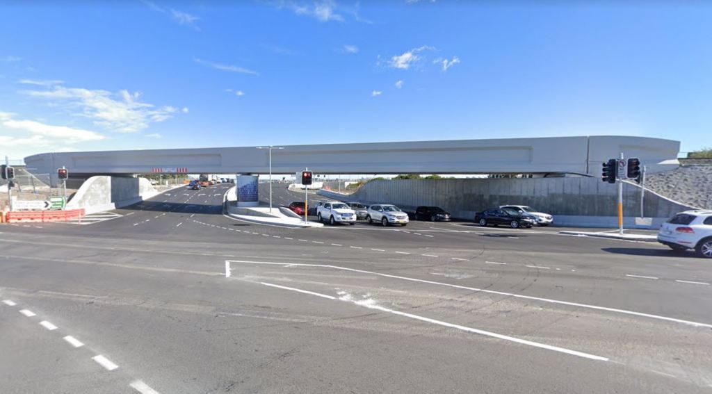
Don’t forget the drain
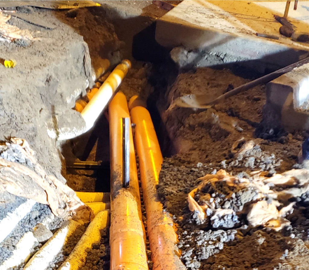
An excavation on my site unexpectedly flooded the other week. It was to connect into an existing storm water culvert at about 8m below surface level, thankfully no-one was in it at the time.
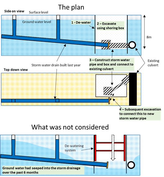
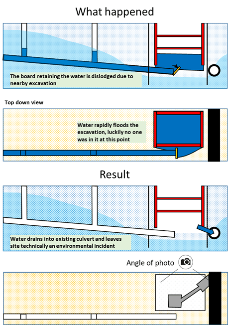
This could have easily been prevented by pumping out the water in the storm water line. It was simply an oversight by the engineers planning it.
As the ground water is contaminated (heavy metals among other things) and this water counts as waste water from a construction site this is also a reportable environmental incident.
Guess the lesson here is not to forget about what you have put in the ground… and maybe check your drains.
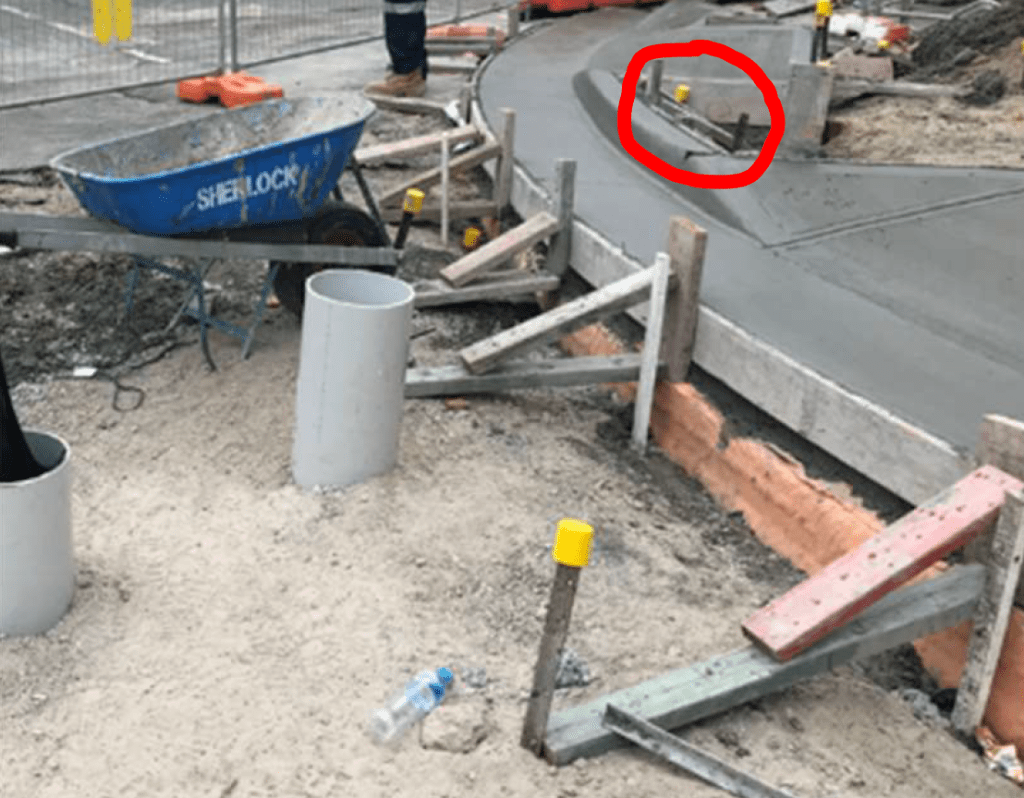
It’s the simple things that can kill you
One of the labourers on my site is lucky to be alive. A few of weeks ago he was removing a star picket (think 2-foot picket) from the ground by hitting it from side to side with a sledgehammer. One of the blows resulted in a 1.5m (reportedly) spark coming out the top of the picket. The labourer was unharmed thanks only to the insulated handle of the sledgehammer and his safety boots.
They were removing formwork from a pram ramp which they had built the day before and had no idea there was an 11kV cable underneath them. The investigation has identified a significant number of lessons, but I feel it all came down to attitude.
- The contractors doing the work were complacent and not engaged with the risk management process.
- The foreman had cut corners by getting a labourer to brief the contractors and had not properly read the permit to excavate.
- The engineer wasn’t engaged with the work and had provided a permit to excavate which was hard to read.
- The senior project engineer who had signed off the permit to excavate hadn’t done their due diligence when reviewing it.
All of this was because they had the attitude that the activity was low risk.
Perhaps the most interesting point is that this is the 14th service strike they have had on this job and they hit a 132kV cable on their last one with an excavator. The lessons identified from that are pretty much the same as this one…
