Archive
Plunging within an existing building
Quick blog for interest as seems to be something that isn’t done particularly often.
Shell House facade is to be retained (previous blog (‘loads of temporary steel’) explains the retention structure). I was asked how the plunge columns were constructed prior to demolition. Here is how it was done:
- Entrance from Wynyard lane increased and slab demolished to allow access for rig to drive in and down the ramp to basement level.
- Demolition of two slabs to allow access for lift in of columns (existing void from L1 up (see 1st and 2nd photo)).
- 21m plunge columns constructed.
- RC crane base cast on top of the 4 plunge columns.
- Stability core and retention system built from crane base.
- Crane tower constructed within stability core.
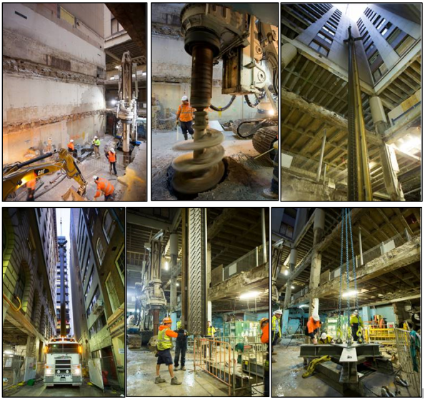 Figure 1 – Plunge Column Construction Photos
DYNAMO MAGIC
Intro
I’ve recently started my phase three attachment with Arup in Sydney and I’m working within the structural team on the Metro Martin Place project which involves:
- demolition of existing buildings
- tunneling for new underground rail line,
- integration with existing underground rail line
- excavation for 5 underground station levels
- construction of two towers with link beneath existing structure (current Macquarie Bank HQ).
A project which Macquarie Bank offered to deliver for NSW government in return for an unsolicited proposal.


Figure 1 – Metro Martin Place Project
Structural Load Take-down
One of my first tasks has been to conduct a manual load take-down for the Northern tower in order to both; produce output which will inform design and, to verify the output of the ETABs model which will be used for further analysis.

Figure 2 – Northern Tower
Dynamo – http://dynamobim.org/learn/
As part of my load take-down I have been asked to use software called Dynamo to provide a code script which will automatically calculate tributary areas for columns on all floors (save lots of time and enables quick auto change to calcs should design/model change) by taking data from Revit, computation in Dynamo then export to excel . Currently working with another Arupian to try figure it out as it has previously been attempted but not finished. Its blowing my mind at the minute as I’ve just started looking into it – if anyone is secretly a king coder and think they can do it then there is a wham bar in it for you…..
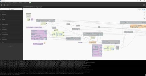
Figure 4 – Indication of current complexity of script map to compute something relatively simple
Loads of Temporary Steel
Introduction:
This seems like a relatively unique engineering feat so thought worth a quick blog to share how I think it works and highlight an issue which will soon need addressing.
The original Shell House structure is being renovated. The clock tower and three sides of the facade stay, everything else goes. Also, an additional 4 storeys are excavated prior to building back up.
Image 1. Original Shell house structure
Retention works prior to demolition:
- Plunge columns
- Crane base
- Stability core
- Perimeter transfer structure
- Clocktower transfer and support elements
Retention works during Demolition:
- Façade support braces inserted as demolition progresses
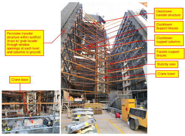
Image 2. Facade retention system as at 24 Aug 18
How I think it works:
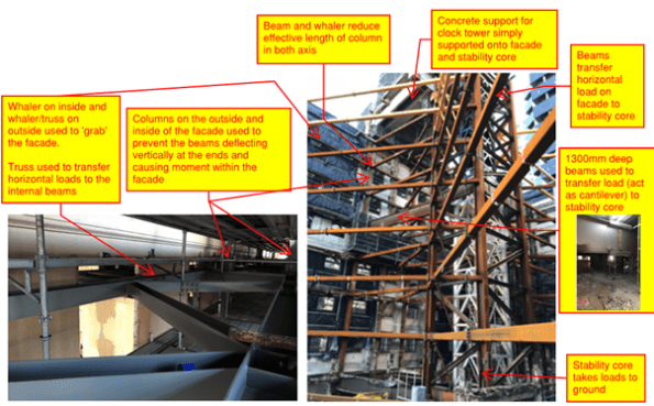

Image 3. How I think it works
Retention works during excavation (soon to commence):

Image 4. Excavation procedure
Issue:
Plunge columns are up to 40mm out of plumb – what are the risks, how can they be mitigated?
I hope to answer these questions in my next TMR so any comments very welcome
Seismic Assessment of a Structure – Fundamentals (Direct Displacement Based Design)
Introduction:
- I’m trying to get my head around some seismic design for the building I’m working on. I’ve done a bit of reading – here is a quick description of my understanding so far, anybody else done any seismic and can collaborate? Any thoughts or corrections?
Assumption:
- EQUAL DISPLACEMENT RULE. (total displacement of an element is roughly the same whether you treat it as fully elastic or non-linear) – proven empirically but the theory is that energy is dissipated when a material yields and therefore the demand on the element is reduced.
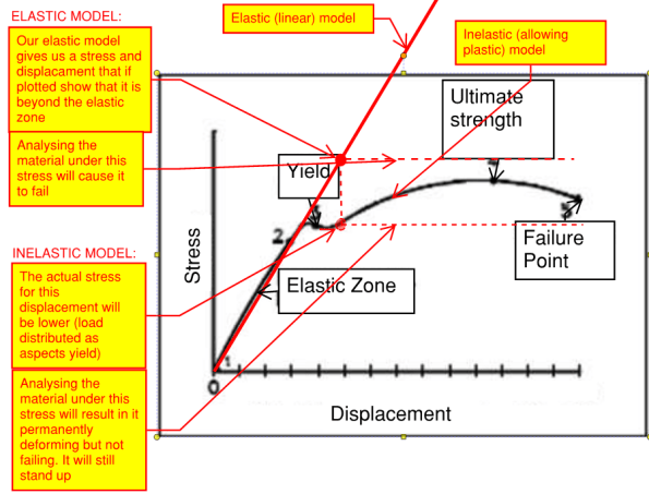
Graph:
 Process:
Elastic Model (or elastic calcs) – FORCE BASED DESIGN (what we are used to):
- Input: Apply seismic loading
- Output: Displacements and stresses
- Compare displacements to SLS criteria (eg inter storey drift max = 0.015 x storey height)
- Check materials can withstand the stresses (in the example in the graph, it will fail)
- However the results may not be truthful to how the material/structure will actually behave – you may be in the plastic zone and as a result, overestimating the stress in the material. There are factors you can apply to bring the stress down but a more accurate approach is to use DIRECT DISPLACEMENT BASED DESIGN
Inelastic model (or non-linear calc iterations) – DISPLACEMENT BASED DESIGN:
- Input: Displacement – input the displacement our elastic model gave us (equal displacement rule). (if you are designing a new build then set your target displacement and start here). The target displacement is then sub divided to create start and end points for each stage of analysis.
- Iterations must be conducted in order to find the critical mode of deformation.
- Output: Stresses
- Check materials can withstand the stresses (in the example above, it will now pass (permanent damage but no collapse))
Other:
- When setting up the model, applying high levels of fixity at connections is conservative (the opposite to what I think is intuitive) because:
Summary:
- Force based design does not allow an accurate estimation of stresses within a structure for material that is beyond yield. Direct displacement based design allows for a more accurate estimate because displacements are more proportional to non-linear behaviour/energy dissipation?
I THINK THIS WALL MIGHT FALL OVER
Introduction
I’m currently on Phase 2 of the course in Sunny Australia. Hi.
I am working on ‘the Wynyard Project’ which involves building a new 32 floor tower over an underground rail station whilst renovating two neighbouring, heritage buildings.
Figure 1 – Wynyard Project architectural render
This wonderful story is about a risk I encountered when looking at demolition plans for 285 George St building (one of the two heritage renovations).
285 George St (figure 2) is a building originally constructed for use by Peapes Tailors but was then altered in the 70s as it was converted into offices. Substantial renovation is required to turn the building into modern office and retail space. Additionally, the building does not currently meet seismic codes or fire regs therefore vast structural alterations are required.
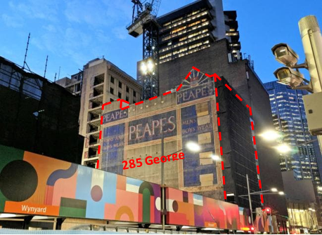
Figure 2 – 285 George St heritage building
The Plan
Demolition and structural investigations are happening concurrently and therefore it is important to identify risk and alter the demolition plans as we go.
In essence, the current demolition plan is to remove some roof structures, create penetrations through the building (for new fire stair, risers etc), demolish all internal fit-out, amend floor structures, and amend openings.
The Risk
I was asked to look at the material load-out for the staging of the planned demolition and as doing so, many risks popped up. In particular, I was concerned with the removal of Slab on Ground, George St level Slab and Wynyard Lane Level Slab (see figure 3, 4 & 5 (bottom left area of each)).

Figure 3 – Section prior to demolition
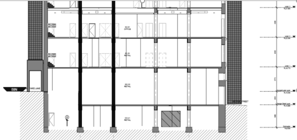 Figure 4 – Section post demolition
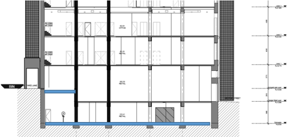 Figure 5 – Section post demolition with new slabs constructed
I believe the removal of the slabs causes several risks (the two major ones being the extended effective length of the columns and reduced number of ‘props’ for the external wall). Here I will concentrate on the risk at the Wynyard lane external wall:
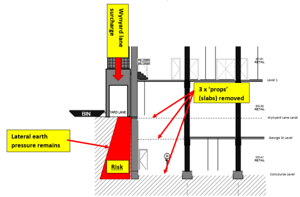
Figure 6 – Risk
I think this gives me two risks within this scenario (Agree?):
- Slide at the toe once slab on ground is removed. Therefore a hinge within the wall at level 1 will also be developed.
- If the foundation holds the toe then bending and shear stresses in the span of the wall will increase when the Wynyard lane and George st level slabs are removed (same forces left to right (Ka), reduced force right to left (slab restraints) = higher bending and shear stresses in the wall)
Is it really a risk?
Structural investigations are underway and no results yet received therefore some large assumptions must be made at this stage (when the results are complete, a structural consultant (Robert Bird Group) will assess the issue and design any temp works required). I have attempted a very crude calculation to see whether it is a substantial risk. I have thrown in some deliberate mistakes to enhance the learning experience for us all…
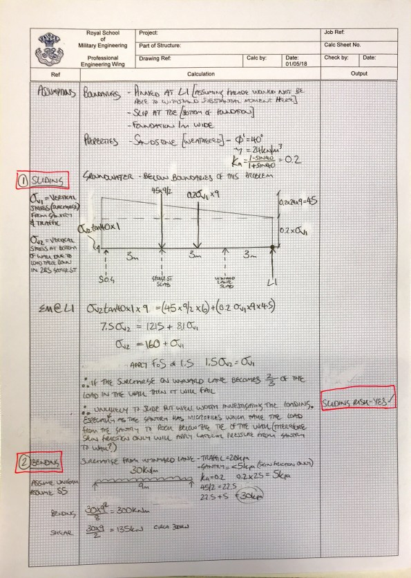
Figure 7 – Crude Calcs 1
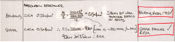
Figure 8 – Crude Calcs continued
Solutions?
Any ideas to mitigate the temporary (figure 4) and permeant (figure 5) risk?
Temp steel props during construction and permanently beef up the wall (reduces floor space/less money)?
