Archive
Pre-setting and Jacking
I have elbowed my way into the team that have been deciding on how to ensure that the design levels will be within tolerance in the finished state and remain within the movement and tolerance specifications as per the NSSS, as well as determining how to optimise this process. This is to be done through pre-setting baseplates and connections and jacking up columns a particular stages.
Within this team, which includes BHL designers, myself and the Mace project engineer, we discussed how to cater for the uncertainties inherent in designing for movement and the change in construction methodology will impact on the pre-set strategy. The the various causes of movement considered are:
Foundation settlement
Column shortening
Elastic elongation of connections
Deflection in beams and trusses
The pre-sets resulting from column shortening are to be accommodated by adding packing plates to splice and base plate locations. Foundation settlement was accounted for by elevating the columns with base packs on the single piles and by elevating the steel comb-cap pile caps.
Deflection of level 5 transfer deck trusses. The original plan was:
- Install Truss with pre-camber to accommodate self-weight of frame above, SDL of frame above and cladding above.
- Construct Levels 6 and 7 (including slabs).
- Jack between transfer truss and level 6 to push levels 6 and 7 back up to level
- Construct Levels 8 and 9 (including slabs).
- Jack between transfer truss and level 6 to push levels 6, 7, 8 and 9 back up to level
- Construct Levels 10 and 11 (including slabs).
- Jack between transfer truss and level 6 to push levels 6, to 11 back up to level
This is illustrated below:


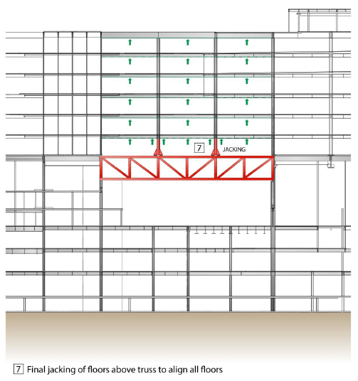
This incremental jacking aimed to avoid high stress build ups in slabs. However it is a very time consuming process so we instructed to BHL carry out further, more in depth analysis with a view to simplifying the process. This showed that the expected dead load deflection of the transfer trusses is around 20mm, which is significantly reduced from the potential movement allowed for during the preparation of their original report and which the slabs would be able to withstand. As a result we have updated the method to install pre-sets at level 5 and jacking is planned only as a mitigation measure as part of an observational method that would likely occur when slabs at all levels are installed as per image below.
A I will explain under the next title, the steel handover level at L5 will be somewhere between design level and full L5 elevated level. This value and level must be calculated to determine the handover level for level 5 and all other levels above and supported off level 5.
So we need to come up with a plan of monitoring the deflection to ensure that it is as per the designers’ expectations. To do this I will survey the levels of L5 connections before they have any load in them, i.e before steel is erected and again when fully loaded. This will show if the trusses are deflecting as expected. If movements stay within the tolerances of the levels predicted by the designer then no jacking will be required. If the movement at level is not as predicted i.e. the level 5 trusses move more or less than expected, the columns will be jacked at level 5 and lifted, once disconnected from the trusses the base shims will be added to or removed to lift or drop the structure accordingly.
Settlement due to altered construction sequence.
An alteration to the programme involved speeding up pouring of slabs at lower levels, this meant that there would be higher loads earlier on, with associated settlements, deflections and elastic shortening.
The mitigating jacking method was based on the optimised and instructed construction sequence agreed at the time the construction analysis was carried out. It was expected only two levels of slabs would be poured at the time steel erection commenced above L5. With this amount of fabric in place the designers believed that the fabricated pre-set would not have dropped significantly. This allowed us to confirm that handover levels would be level 5 design level + full pre-set. However the changes meant that the level would be somewhere between design level and level 5 elevated level at level 5 handover.
We need to know what level to build the steel to above level 5, taking account of the movement that will occur earlier than expected, in order to know if it is within tolerance. To accommodate this I have collated the as built survey levels of column base plates, and have organised a survey to take place again when all floors have been poured up to level 5. This will show the amount of settlement that has actually occurred. The steel supporting the slabs above level 5 should be set at level = design level + pre-set – actual movement below level 5.
They keep slipping up
A really juicy one here on concrete for the E&M’ers to get their teeth stuck into.
Here is something to watch out for if anyone is involved in slipforming.
-
- The four shear cores in my area at Battersea are being built using slipforms. The main benefit of this method is that it can be constructed very quickly (if carried out by a competent contractor with adequate round-the-clock quality assurance).
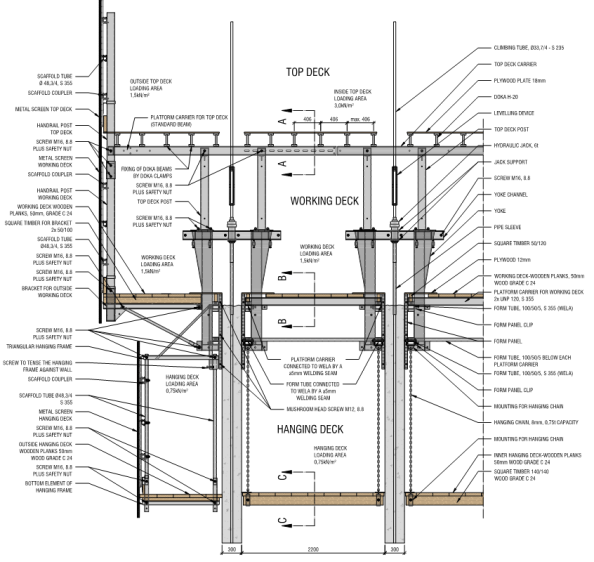
- Quick recap on Slipform: Shuttering (the formwork) is attached to yolks, which are held up by climbing tube. The slipform rig is held up entirely by the climbing tubes which run to the base of the slipformed wall, and the jacks are almost continuously lifting the slipform rig. The concrete that is exposed below the shuttering only needs to support it’s own weight, which is continuously checked as the slipform is lifted.
- The axial force produced by the jacks must overcome the friction between the shuttering and the concrete to allow the shuttering to move up. However, if the shear force due to friction between concrete and the shuttering overcomes the shear strength of concrete then the concrete can fail at the surface, resulting in poor finish. If the concrete has cured and the shear force overcomes the tensile capacity of the concrete then whole sections of wall can be dragged upwards. This happened on one of the cores in Battersea, resulting in large tear-outs and long delays.
- Sub-contractor’s reasons: The high strength C75/85 concrete that was used in this particular section of wall was going off too quickly, resulting in it adhering to the shuttering. A possible but flaky argument trying to transfer the blame to the concrete mixers.
- Weapon fires, weapon fires, weapon stops… The concrete was repaired using traditional formwork on the hanging deck, and after 8 days of repairs slipforming continued as normal… for a few days until the same thing happened again in an area where the normal C50/60 concrete was being used.
- What was the reason for failure? Slipforming is supposed to be a continuous process, so that the concrete is given time to harden in order to support it’s own weight, but not given too much time because it can adhere to the shuttering. Also, this means that there will not be weak ‘construction’ joints with the concrete below which will give the concrete poor tensile strength.
- First incident (photos below): There had been a long pause in order to fix some large steel embedment plates before the concrete was poured. The concrete was poured on the night shift, where as it later emerged, the subcontractor had no QA managers working and an inexperienced concrete foreman/supervisor. It is possible that the high strength concrete was going off quicker, but this should have been anticipated and either arranged to be poured quicker or designed with admixtures to slow the curing process. An operative on site also let slip that the concrete looked as if it had gone off when it was poured.


- Second incident: (photo below) After the first incident, the exposed shuttering was cleaned, however the shuttering overlaps the concrete at the bottom by about 0.4 m to allow a good seal when pouring concrete. It is likely that in this area there is a film of concrete that has stuck to the shuttering, which makes it much easier for fresh concrete to bind to the shuttering. The failure occurred after a very hot day, which is likely to have compounded the problem due to increased speed of curing.

- After some investigation it seems as if the most likely problem is that the sub-contractor has not been managing their logistics well, allowing concrete to stand on site, or having large quantities turn up at once causing queuing. It seems as if there were two failings here; in logistics managemnt and in Quality Assurance. A real Sliphopopotamus.
Grouting a tree
This load-bearing architectural feature called a tree column is causing some problems.
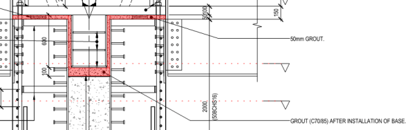
Grout will be poured into the void shown in red after the base has been installed. The designer/ Mace/ architect combo are worried that there will be voids in the grout.
Suggestions so far have been:
a) To measure the volume of grout poured in.
b) A mock-up has bee created to test construction and finish. They are proposing to cut this in section to check the grout.
The client weren’t satisfied with Option a and option b is ok but doesn’t check the actual tree columns.
My idea is to do option A and then use electrical imaging on both the mock-up and final tree-columns. Is this feasible, can electrical imaging be used for this type of thing? or are there other alternatives?
Batter… that’s something you put on fish right?
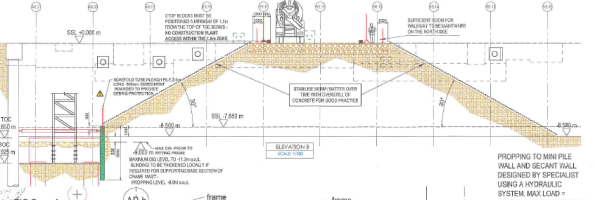
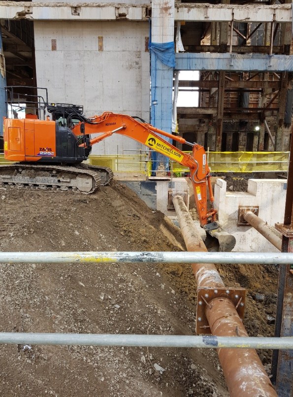
I’m working on Phase 2 of the Battersea Power Station Development Project (the actual power station bit). This post is related to Heath and safety on site. On the surface of it they appear incredibly H&S conscious, with a site flooded with orange jacketed traffic marshals and slinger-signallers and the logo “safety first, second nature” plastered everywhere. However, with a bit of digging below the surface (quite literally) they don’t seem to be quite as worried about the slightly less obvious but potentially incredibly dangerous situations. This lack of safety manifests itself in two ways; 1) constantly putting workers down deep excavations without any attempt at slope stabilization and 2) loading the top of steeply battered slopes. The second of these situations is the one I’ll go into detail on.
The situation shown below grabbed my attention on site because the slope batter looked to be at an angle that is too steep to support construction plant so close to the edge. I mentioned this to the supervisor and construction manager on site, who were not worried, believing that 45 degrees was an “ok” batter (I think that 45 deg is generous). Recalling that the thi dash/2 plus 45 rule goes out of the window when loaded, I was not sure about this, so checked it with some analysis on Geo5.
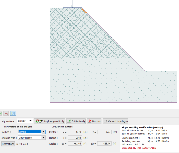
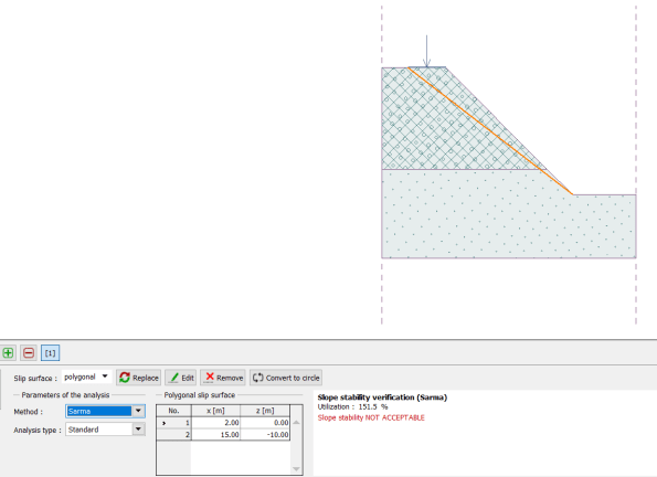
 Some quick calculations on Geo5 using the information obtained from the Ground Investigation Report show an unstable slope.
Load (mass 23000kg) = 226 kN
Modelled as a distributed load over the area of the excavator.
The ground profile is not certain, due to the possible presence of a scour feature. I have taken the case as being in the Short term, as the excavation is only to be at this angle for a couple of days. So the worst case is with granular made ground from 0 to -8, and scour infill from -8 to -15.
After some more digging (i’m sure this pun has been done 100 times before on this blog but it’s worth getting it in), I also found the Risk Assessment/ Method Statement, which states that the safe batter is 30 degrees, and that stop blocks should be positioned a minimum of 1.1 m from the edge. I informed my supervisor, who is also the senior project manager in charge of ground works, who said that he would look into it. They have since carried out a deeper excavation on a steeper slope elsewhere. 🙂