Archive
Concrete or Steel Roof Sir…..Are you sure?
ith the 30% concept design completed and off for approval I thought I had arrived at the start of the detailed design. Armed with my vast amount of knowledge and more importantly a phone line to the rear guard in Chatham I was ready to dive into some detailed engineering calculations…or so I thought.
Turns out that since January the design has been turned inside out and some fairly significant design issues uncovered that should have been mentioned in the 30% design.
Concourse Slab Strength. The concourse slab has not been design to carry any further load other than those loads present I the permanent state. During the temporary state the concourse will be required to hold the form work for the roof slab. As it turns out it has not been design to hold the additional load of the wet concrete roof slab as it cures. As a result the propping for the roof slab will need to extend through the concourse slab with either large props passing through the concourse slab or a forest of props at both levels. As this is a bottom up build the contractors plan and the project programme is based on the M&E fit out occurring concurrently as each subsequent level is completed. With the proposed forest of props at the platform level the contractor will not be able to complete the M&E fit out until the roof slab has cured. This puts the project programme at significant risk.
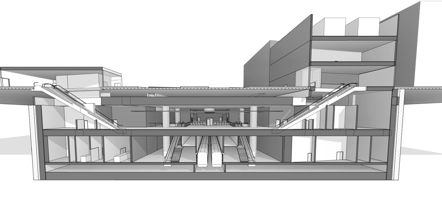
Current sections of architect model. The odd shape accopunts for a Highway fly over foundation,road junction and buried services. Section shows platform, concourse and roof slabs
Steel or Concrete Roof. With the issue of concrete curing times and excessive propping the contractor proposed a change to the design that saw the concrete roof slab replaced by a steel beam and precast concrete roof. This particular issue was passed to myself to see if it could be done. Given that some of the spans are nearly 30m this would require some fairly large beams…turns out about 2m deep plate girder beams with 80-100mm flanges should just about do it. The issues faced when designing the concept for the beams are outlined below:
Supports as the rest of the structure is concrete the tying in of the steel beams to the concrete supports to make full moment connections would be particularly difficult and is likely to result in excessive cracking at the interface of the steel beam and concrete. Cracking as my previous blog is a particularly sensitive issue on this project. Therefore the beams would need to be simply supported.
Simply supported beam results in a high bending moment at the mid-section of the beam as the beam is free to rotate at the support and no moments are passed to the concrete. As a result the beams would need to be deeper than if the beams supports were encastra.
Deflection. Given that the beams would be in some cases spanning nearly 30m the deflection at the midpoint was in some cases up to 100mm. Not a large deflection I’m told but any deflection of the beams would encroach on the architects and M&E services spaces. To counter this I suggested that the beams could be pre cambered i.e cut to account for the deflection so that as they did deflect they would then settle at a level.
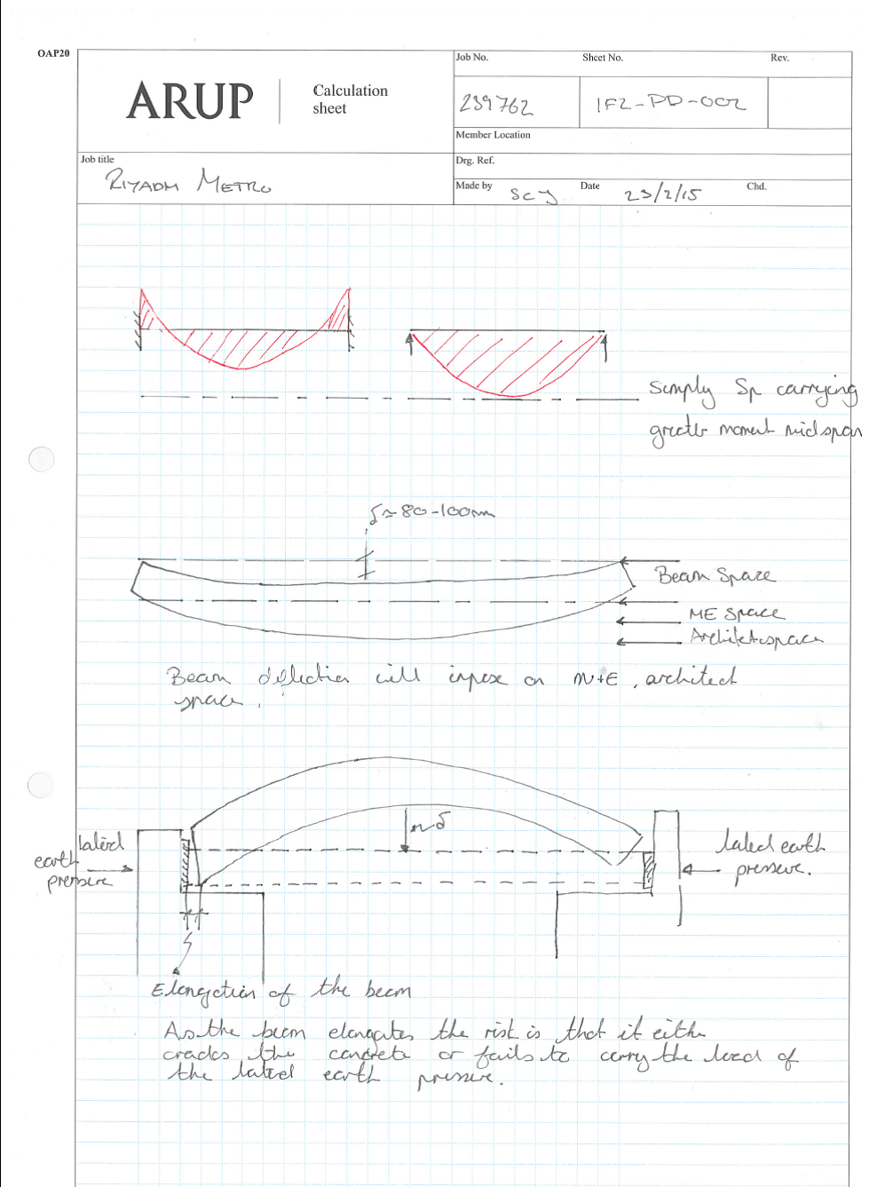
Elongation. With deflection now sorted my attention was turned to the elongation of the beam. As the beam would deflect from a pre-determined camber to a level that beam would also elongate. As the beams were to be simply supported but would also be required to act as props the beams would have to once extend and rest on a bearing to carry the axial load from the ground and support the box. To ensure this actually happened would be very difficult given design and construction tolerances.
Bearings. It occurred to me that as the roof slab would also be forming the foundations for a mina high way, in a way I was designing a very wide bridge. Any steel bridge usually sits on some sort of bearing and bearings need to be replaced usually every 25 years. The design life of the building is 150 years…and the question to the team how would any maintenance of the bearings be completed, how would bearings be replaced.
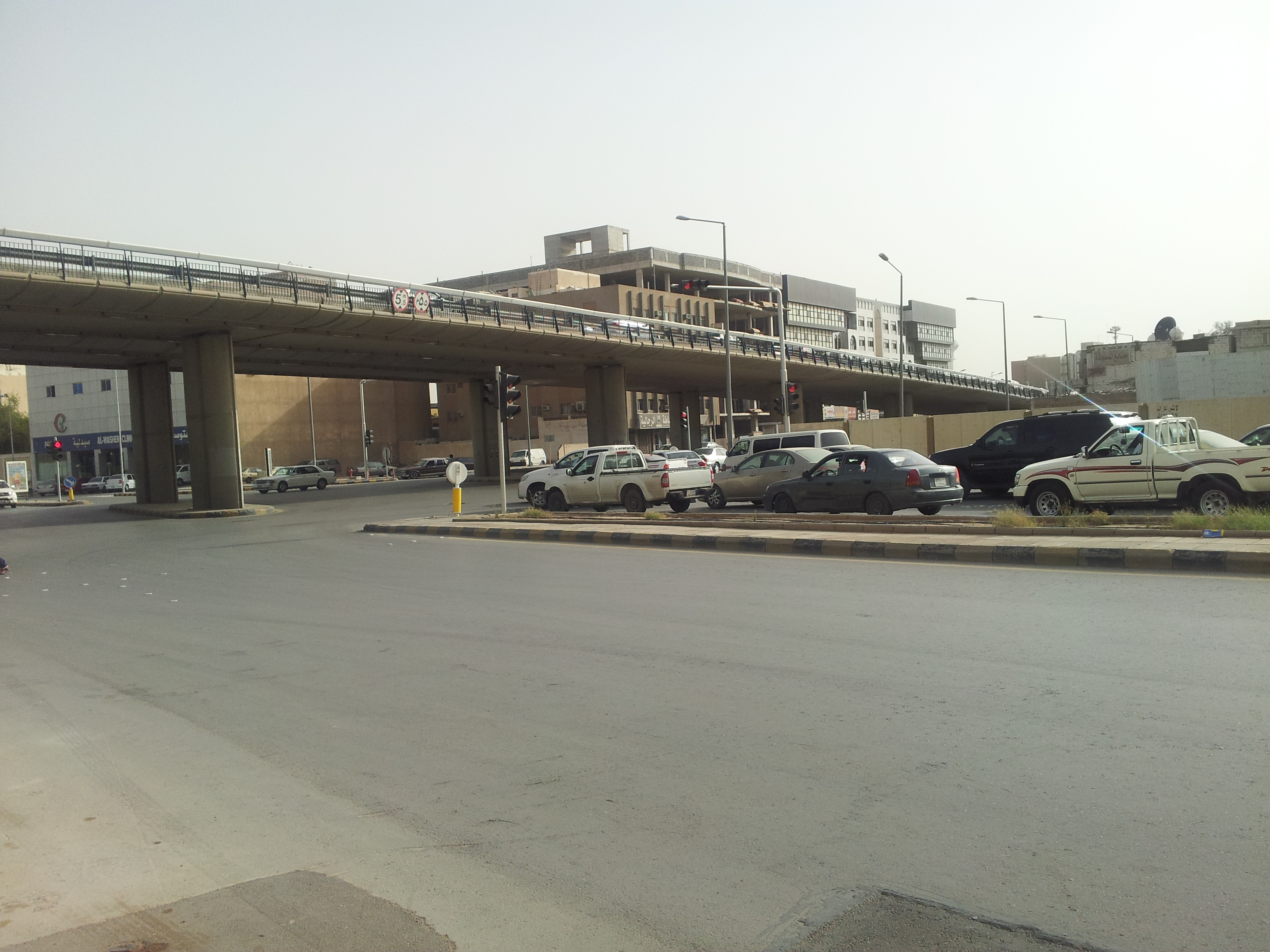

Pictures of the King Fullah Road that the station will be beneath at the end oc construction.
There were already a number of problems that I felt the team had missed or were choosing to ignore. As the report was being complied to inform the client that the roof could be completed in steel which would aid the construction programme I felt that we were not advising the client on the second and third order affects of the changes from concrete to steel.
With the risk of making myself a very unpopular individual…well more so then currently. I raised the issue outline above along with: transportation of 30m spans of steel, the fact that Riyadh does not have a steel industry and therefore steel beams would need to be fabricated and imported. My aim was not persuade the client either way but simply to ensure they had all the facts and could make an informed decision.
This has made for a few uncomfortable meetings, however I’m sure that we as the designers have the moral obligation to ensure that a client is fully informed and not simply to follow the blind beliefs of the contractor.
Concrete Cracking I never knew it was so exciting…..it isn’t!
Background and problem. Within the design specifications for the Riyadh Metro there appears to be on the face of it an oversight in terms of the concrete specifications. The design specifications state that the maximum 2. allowable concrete crack width is 0.15mm. From my now understanding of concrete cracks this is considered to be exceptionally low with the BS and EC specifying a more usual crack width of 0.3mm. The only time that a smaller crack width is usually specified is for water retaining structures. As part of the team and as I showed an incline of interest at one of my first meetings I landed the role of leading small team (myself and on other) in the study of concrete cracking and the means to control it.
The reason behind the particularly strict crack widths is the durability of reinforced concrete within the particularly harsh environment of the Middle East. In the last couple of decades, the region has experienced significant growth in construction with a increased use of reinforced concrete as a construction material. Despite the generally accepted increased durability of concrete over other materials many of the structures are showing signs of deterioration within the 5yrs and the majority will not last the intended design life. A lack of understanding of durability factors in the initial design and construction combined with the use of unsuitable materials, poor workmanship, and lack of knowledge of the environmental affects on the concrete are considered as the underlying factors that lead to the two primary means of concrete deterioration within the Middle Eastare (que dramatic music);
1. Reinforcement Corrosion
2. Sulphate Attack.
In both cases the permeability of the concrete and the exposure of the reinforcement to the harsh environmental conditions is a key factor. Key to the permeability of the concrete is crack width.
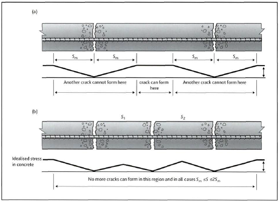
Crack widths are a function of the tensile forces within concrete and the inability for concrete to carry tensile stresses (not strictly true, but very low). There are a plethora of mechanism that cause cracks within concrete, however as the designers for the minute we are tackling the one we have most control over first, flexural cracking.
Flexural caking occurs due to loading of the concrete. As a length of reinforced concrete is loaded the tensile stress cause the concrete to strain at the point at which the concrete cannot strain any further a crack forms and the tensile stress is reduced to zero. The tensile stress then builds at a distance from the crack until the concrete can no longer strain and another crack occurs. As the tensile stress continue to build cracks are further opened until the stress is taken up by the steel reinforcement.
The principle factors affecting the number and width of cracks are
1. Cover – the greater the cover the greater the area of concrete that must strain prior to transfer of tensile stress to the steel.
2. Ratio of effective steel. The greater the amount of steel within the effective depth. This can be achieved by using a greater number of smaller bars.
3. Using smaller bars. Smaller bars have smaller diameter so can be placed closer together reducing distance between bars and so reducing concrete outside a zone of influence. Smaller bars also have an overall contact perimeter with the concrete.
4. Use of higher bond bars or reduce the tensile stress within the concrete. Fairly obvious however in our case the materials used are 355n/mm2 steel however the concrete is only C35 and that is considered good in Saudi Arabia.
Solution. The solution has not been entirely obvious or easily negotiated. The obvious answers of adding more steel and reducing the cover are not quite so straight forward. Reducing the cover would expose the concrete and reinforcement to the risk of cracking during curing due to thermal shrinkage as well as plastic settlement and plastic shrinkage cracks (both not discussed here). A reduced cover would also make the concrete vulnerable to chemical attack.
Just adding more steel is also not viable as the greater the amount of steel either the concrete section needs to get larger which will exacerbate the problem or the steel must be stacked in layers. As the steel gets further away from the surface the less affect it will have in the prevention of cracks as the lever arm to the centroid reduces. Greater layers of steel will also reduce the effective depth (distance to centre of steel from centre of compression zone) of the concrete section and eventually the steel will enter the compression zone and no longer be effective in crack prevention.
The solution has been to look at the use of stainless steel as the outer layer of steel and reduce the cover. This will increase the effective depth and reduce the amount of steel required to reduce crack widths. The results of the study I have been leading on are below.
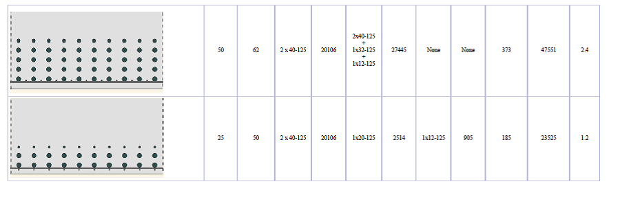
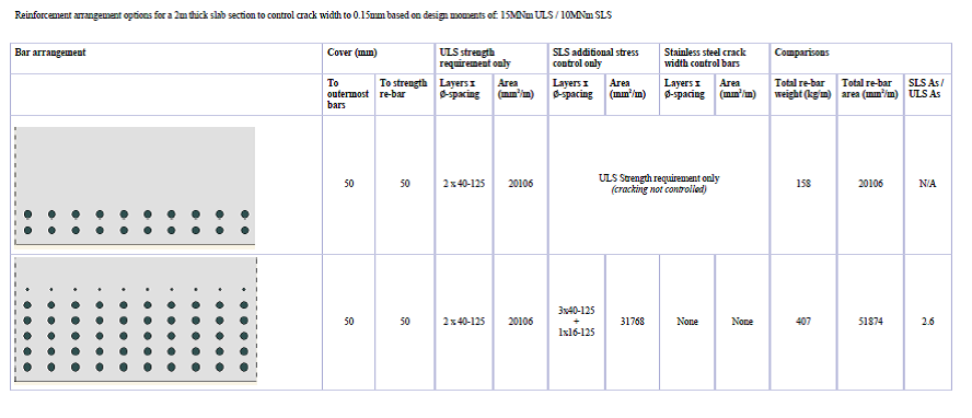
Sections in order 1-4 (top to bottom) all show a section of concrete subjected to a bending moment of 15 MNm a fairly typical load case for the Riyadh |Metro project
- Shows the steel required to carry the tensile loads within the concrete section
- Shows the additional steel required to control cracks to less than 0.15mm with a cover of 50mm. Note that the addition of further steel having a decrease in effect in reducing the crack widths, with further layers of steel only reducing crack widths by a smaller and smaller fraction of a mm.
- The addition of smaller bars in between the larger bars but maintaining the cover reduced the steel requirement as the effective depth was increased. Cover was maintained at 50mm and cracks widths were limited to less than 0.15mm
- The addition of stainless steel within the original 50mm cover reduced cover to 25 mm but further increased the effective depth and allowed the removal of further crack control steel from within the concrete section.
Conclusion
Conclusion to the study was that while stainless steel may be more expensive the use of stainless steel would remain cheaper then the use of additional steel to control crack widths.
In other news the office had a jazzy shirt to work day to raise money for charity. After a rather uncomfortable journey on the underground I arrived to work to find that I was one of only a handful of people to have participated and ended up looking more of idiot in a client meeting then I normally do.

Yep the design office really is that exciting.
Riyadh Metro – Ground Water Risk, again!!, but different!!!
Now at the end of my second week with Arup I have found a desk, computer and even taken some time to find the library check out some books and remind myself what a bending moment is. Not sure why I am surprised but a have found copies of most the books we were issued on course either in the library or actually being used by engineers around the office.
I have been assigned to the Riyadh metro team and once again find myself looking at trains underground.
Project in brief
The Riyadh Metro is part of a wider scheme to regenerate the public transport system around the capital city of Saudi Arabia called the Riyadh Public Transport Project (RPTP). The metro system is to be a rapid transit system designed to reduce congestion within the city due to the rapid growth in the size of the population of Riyadh within the last 10 years. Construction of the metro system began in April 2014 and is due to be completed in 2018.Once completed the Riyadh metro consist of six lines totalling 178km of track and 85 new stations. Arup have been employed as lead design consultant by BACS consortium consisting of Bechtel, Almabani General Contractors, Consolidated Contractors Company and Siemens. At Arup the Riyadh metro team is responsible for the design of the five subsurface stations along the Green and Blue lines. At my time of arrival the 30% concept design has been completed and the team are now turning their attention to the 60% detail design phase. I have been assigned to the team looking at station 1F2 which is considered the most complex of all the stations. The complexity is due to the interface of already existing buildings, a main highway (under which the station is to be built), a flyover and testing ground conditions.
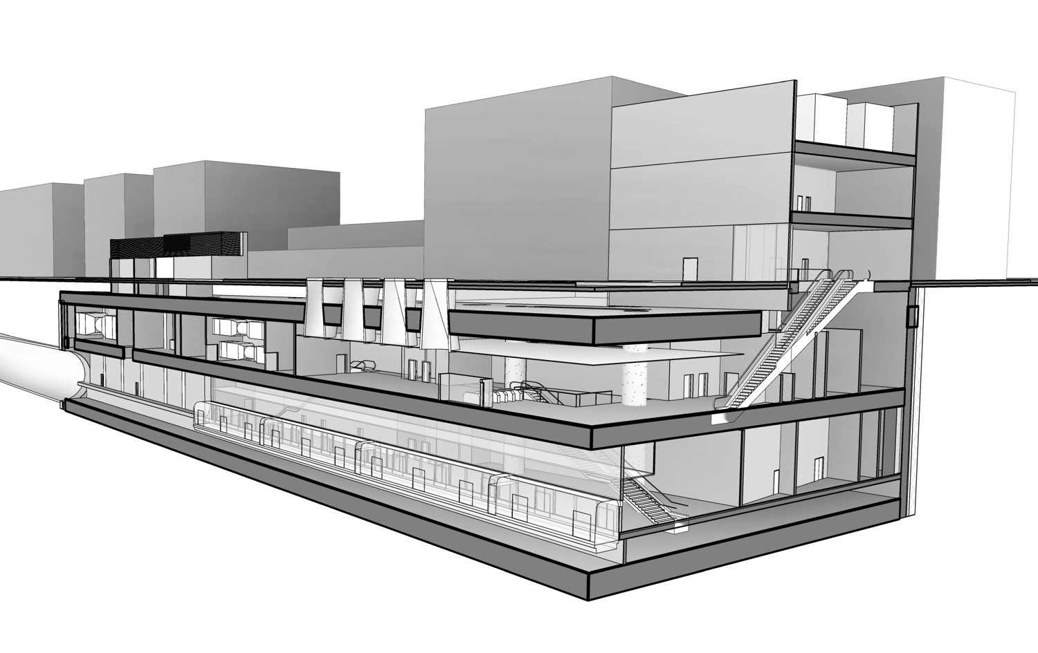
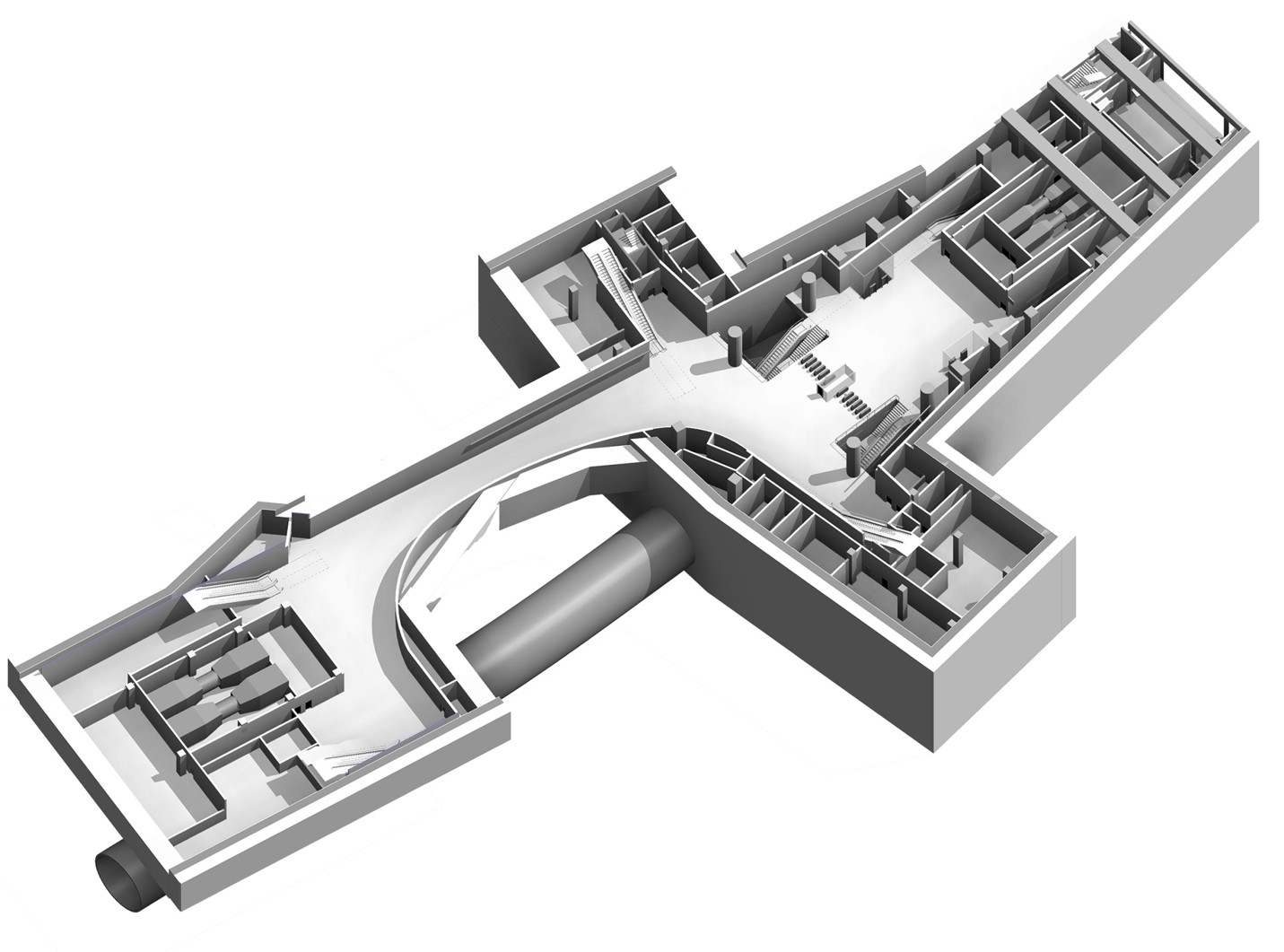
Fig 1. Station 1F2 structural model.
Construction Method: The construction of 1F2 is to be a bottom up construction unlike the Liverpool street station which was a top down construction. The use of a secant pile diaphragm wall with tension anchors into the soil behind the piles will be used to maintain the excavation. The structure will then be built from the bottom in a conventional method.
Soil Conditions: Although not read into the detail the ground conditions on site are set to be quite different to Liverpool Street. The ground is predominately course grain gravels, sands near the surface with more consolidated soils at depth and ultimately layers of rock.
The Engineering Risk.
Ground Water: The main engineering risk identified in this case has been ground water due to confined aquifers and a high water table and high permeability soil. The high permeability of the soil combined with an wxpectation of large fissure will result in a high flow rate of ground water which will fill the excavation and pose arisk to life or at the very least make conditions unworkable.
Settlement: Any attempt to lower the water table will also alter the voids ration and cause settlement of surrounding soil and poses a significant risk of causing damage to surrounding structures.
Solution
Reduce the ground water flow. Ground water flow (Q) occurs when a change in the ground water regime sets up an hydraulic gradient (i), i.e. opening an excavation. The greater the difference in head the greater the hydraulic gradient and the greater the flow, however the length over which the water must flow will also affect the flow of water due to resistance caused by the permeability of the soil. As a result
Ground water flow (Q) =Cross section area (A ) x permiability (k)/flow length (l) x (h1-h2)
Hydraulic Gradient (i) = h1-h2 / l
Therefore there are a number of ways to reduce the ground water flow into the excavation, one using a ground water pumping regime to reduce the difference in hydraulic head or increase the flow path by forcing the water to flow further using a hydrulic cut off.
Ground water pumping reduce head difference: My usual approach would have been to design a dewatering scheme to lower the water table outside of the diaphragm wall to ultimately lower the ground water within the excavation. However due to the risk of settlement and damage to structures within the influence zone this has been deemed unsuitable. Therefore de watering must take place within the excavation.
Ground water cut off increase the flow path. In order to reduce the flow of the water a vertical cut off may be used to reach a lower permeable soil boundary or to increase the length of a vertical cut off to increase the length of the flow path and reduce flow. A typical method for achieving this is the use of piles either sheet or RC concrete. The geotechnical team within Arup have opted to used injection grouting at the base of the pile to create vertical cut of. In this case a TMS (Tube a Machete, read tube with holes in it) is inserted through the pile and grout injected in to the soil to fill the voids. The intention is to us a course grain grout followed by a finer grain grout to create the vertical cut off and reduce the dependency on augured piles.
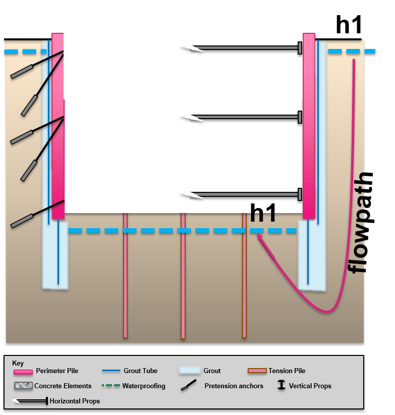
Fig 2. Showing use of grout as a vertical cut off to increase the flow path.
My initial thoughts are that this seems very high tech and potentially engineers trying to be too cleaver. The problem that I raised but apparently has been considered is that the first that anyone will know it has failed is when the excavation starts to fill with water. In this instance it would be too late to increase the length of the secant pile wall to increase the vertical cut off. I stand by to be corrected.
Comments on a post card…..
Capts Blog – A final word
Has nine months really passed, time on attachment has gone very quickly. As I leave Liverpool Street here is a quick update on my areas of responsibility.
Site in General. At the time of my departure we had just completed the concrete pour for the penultimate slab at 78SSL and works had commenced on the excavation to the final level 73 SSL. All in all some 2,400m3 of concrete poured and nearly 2000 tons of steel fixed in the preceding slabs. The final excavation would prove the most complex as a the break out of the pile wall to create the access tunnels to the platform would need completed. During the breakout of the pile wall a temporary section of slab would be required carry loads across the sections of pile wall. I have intentions to return to the site to witness the pile wall breakout as the plan is to use a steel and diamond rope in a winch to cut the piles like a cheese wire……I would like to see that as the piles are 1200diameter with heavy steel reinforcement, but I have been told it is possible.
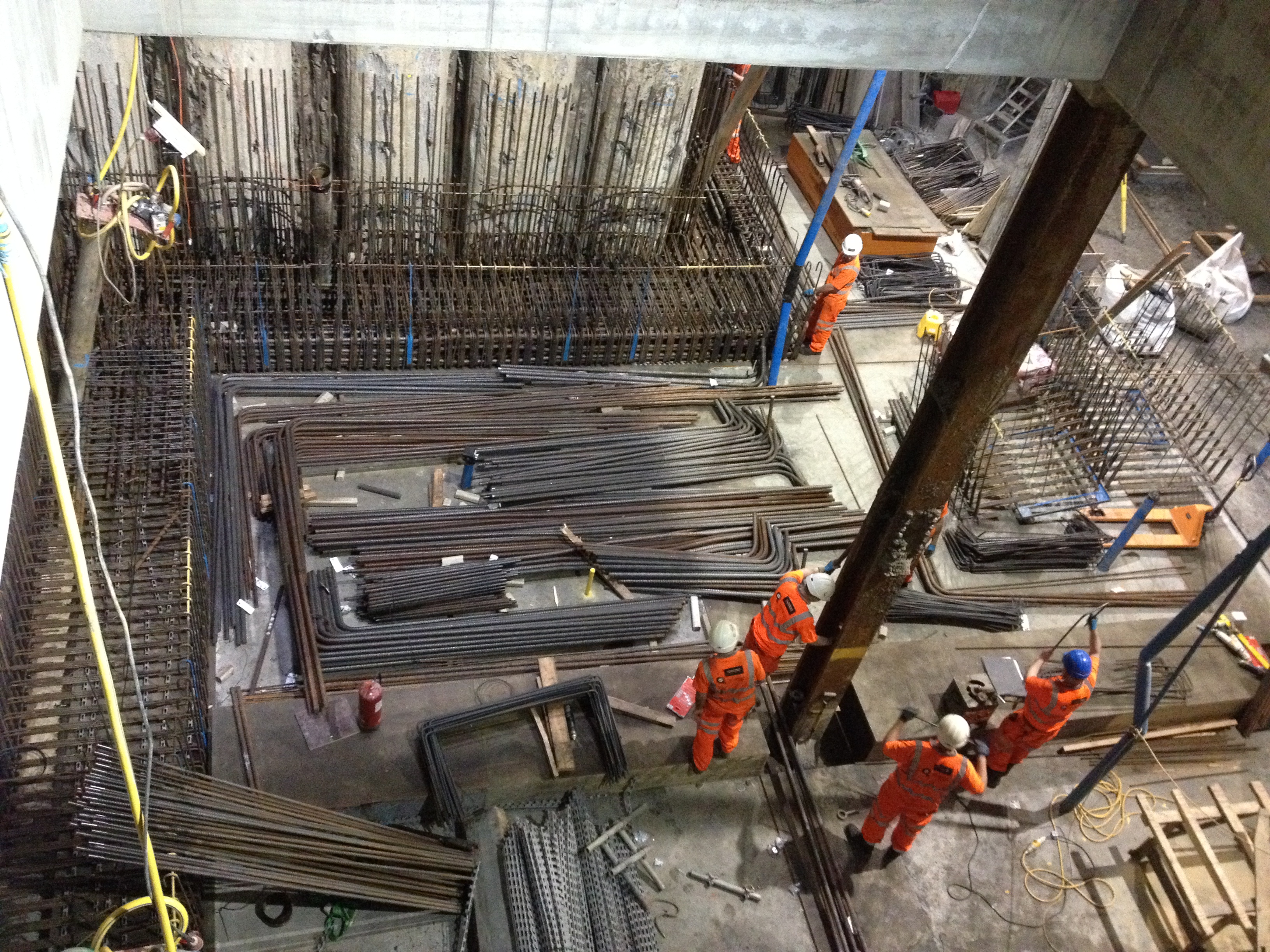
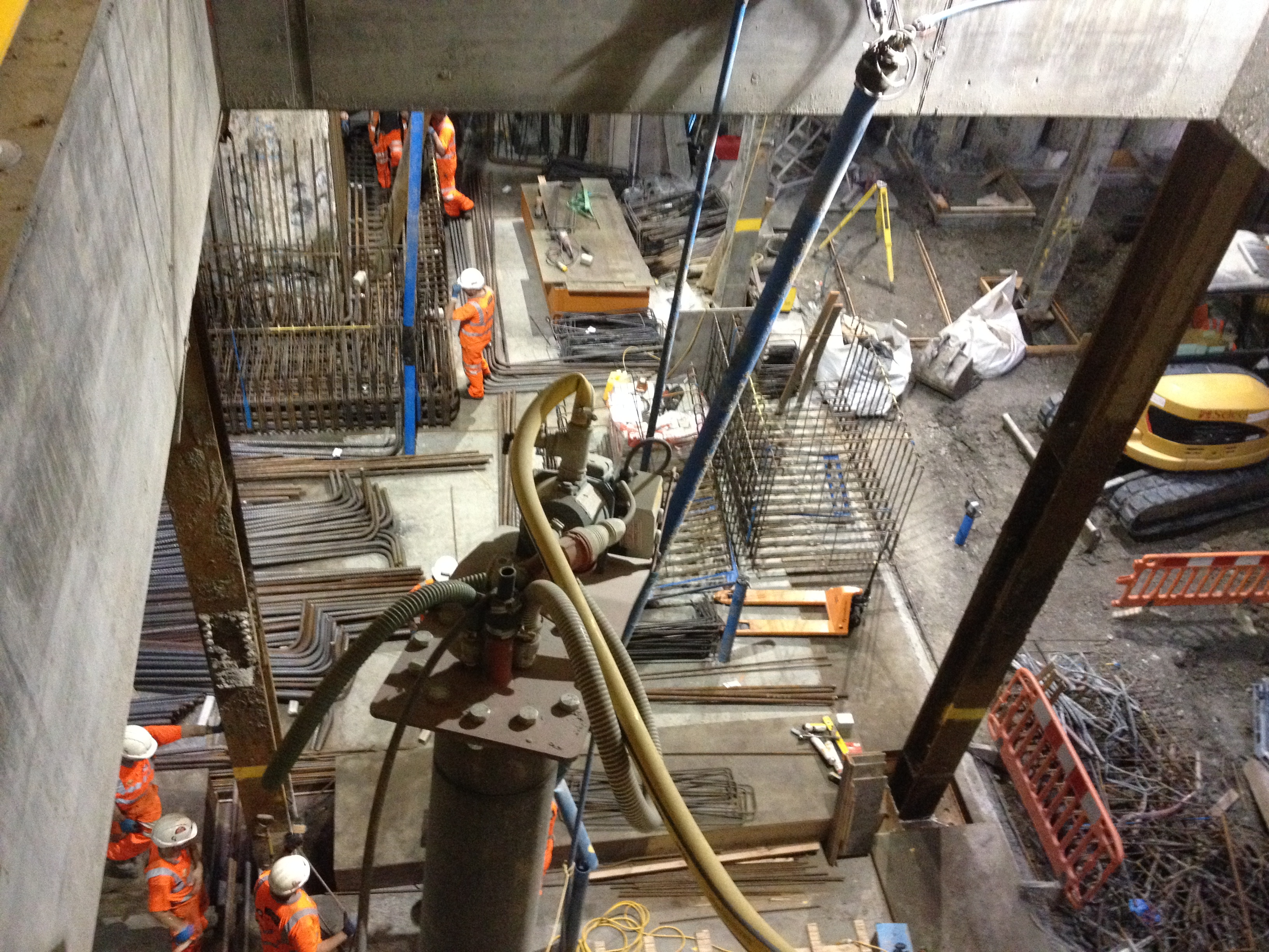
Installing steel at the penuletimate slab level & view of the running tunnels adjacent to site
Depressurisations wells. My part completed wells installed, working and a steady decline of the pore pressure had allowed the cessation of works to be lifted and the excavation to continue. Having now entered the Lambeth Groups of soils and with the wells firmly in the course grain gravelly layers the amount of water being pumped had dramatically increased from 200-300litres per day to20,000 per day. All was going well up until my last day when we arrived at work to discover the site flooded from an over flowing settlement tank, the cause turned out to be that the contract excavating the tunnels adjacent to our site had turned their dewatering system off on the Monday and it had taken a week for the recharge of the ground water to reach our site. Although the wells we had installed were capable of pumping the increased amount of water we did not have sufficient storage capacity. It also turned out that the young apprentice responsible for monitoring the flow rate had neglected to do this and so the increase in water flow had not been picked up.
Installing the depressurisation wells & the well head of the vacuum edjector depresssurissation system
Precast Concrete. Leading the charge for Laing O’Rourke I had at the time of leaving managed to secure my greatest legacy to the Liverpool Street site, the use of precast concrete sections to complete the Northern Wall of Blomfield box. Through the use of negotiation skills, professional engineering judgment, coercion and by being a deviousness and sneaky bustard I coordinated efforts and produced the Value Engineering proposal that convinced Crossrail Engineers that the use of Precast Concrete was in fact the best option in terms of engineering risk, H&S and commercial risk.
The complicating factor in the design of the precast concrete sections was Crossrails insistence that as they would be required to take structural design responsibility then they would design the wall sections and inter wall connections. As the wall is to be next to live LU track and undercover the wall must have little to no maintenance burden and cannot use any materials that release toxic fumes when burnt. As a result Crossrail had designed the walls connections as an insitu concrete stitch creating two problems for us as the contractor to overcome; Firstly this insitu stich requires the reinforcement within the wall to be tied to the structural frame of the building and then concrete poured between the steel to join the wall and structural frame together to form what engineers have described as a monolithic structure. Secondly how do we turn and ten support the wall sections during construction. The walls have a long slender overhanging nose section that cannot be used to support the wall during fixing and pouring. With the temporary works team we had developed a rough scheme of manoeuvre using Perri Strong backs to create legs to support the wall. These legs then had to be offset from the wall sections to allow the site operatives access to fix steel and pour concrete. As a result at my time of departure I was working with the temporary works team to model the loads on the connections. At the time of departure we were on the 6th iteration of concept designs from the design consultants Motts….
I have now moved to Arup, London office without a speck of mud insight. I am now surrounded by a mix intellectual geeks and glamorous Europeans. I have discovered the free lunches that accompany the lunch time CPD sessions and have attended two this week already. The festive season has already started with a wear your s***test shirt to work day and festive if not geeky pub quizzes…John I am sorry to disappoint but my team came last at the geotechnical Christmas quiz…….
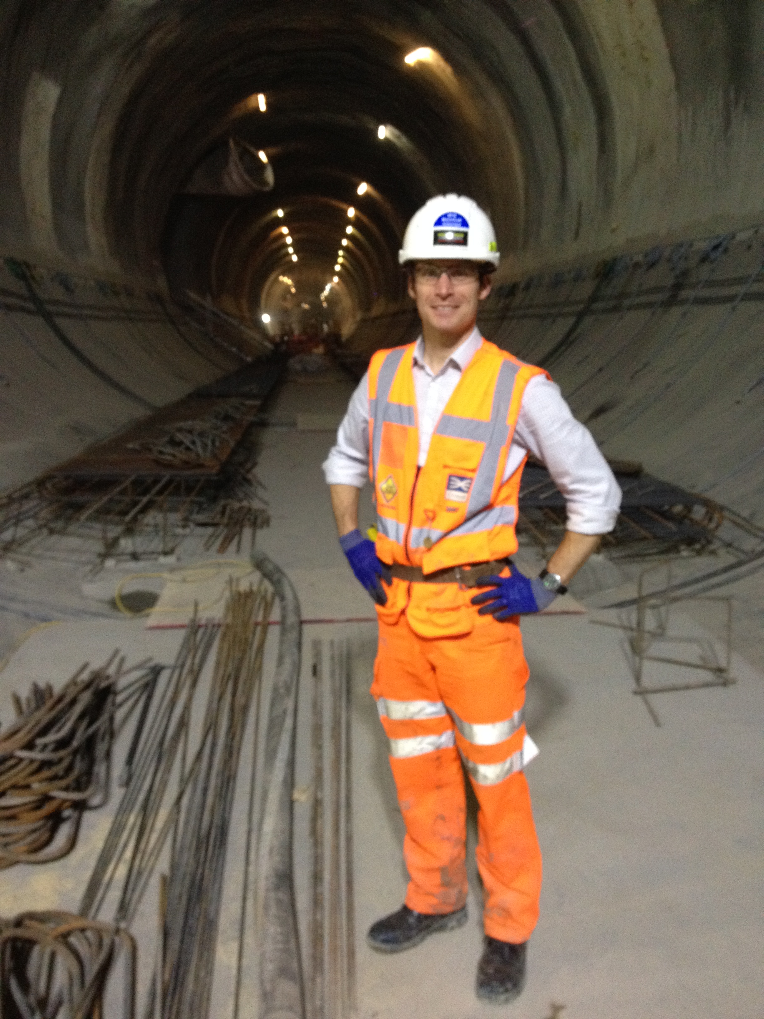
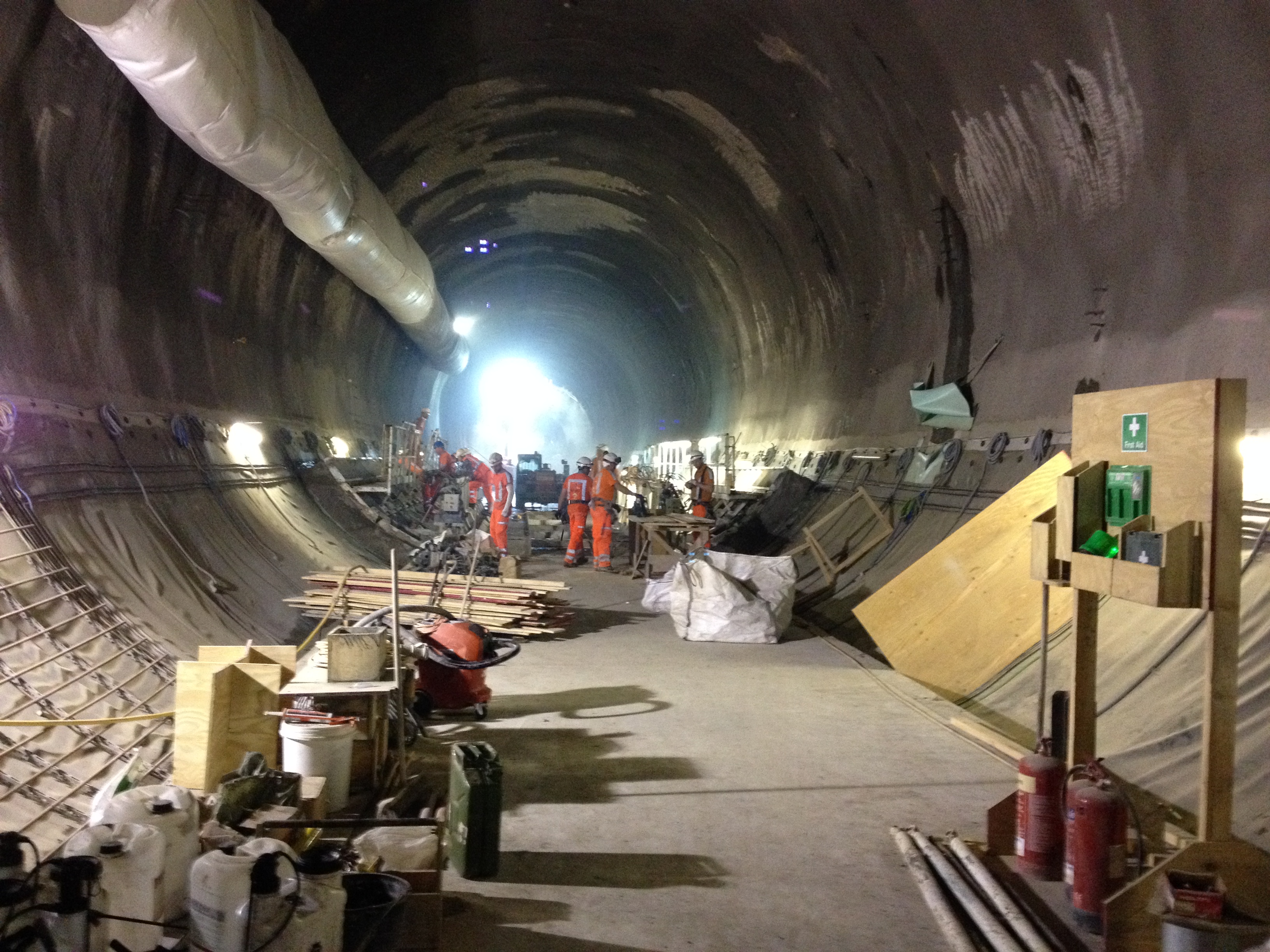
My final walk in the tunnels and on site
Risk Assessments
Risk.
Asked to conduct a survey of a capping beam i looked to install a suitable access via a ladder and then use a harness to secure myself to the outside edge of the capping beam. At this point I was told that this was considered dangerous and that should Crossrail spot me i would be asked to leave site. The Junior engineer told me that we should wait until Saturday when it would be quiet and no one would see me accessing the capping beam. I entered a short argument during which I pointed out. The survey would take a maximum of 5 mins and that the two approaches that the other site engineers wanted to take were wrong.

View of capping beam. Survey required of right edge, acces via broken ground behind orange pipe next to exposed scafold bars
The Options
Overly Safe. The option considered safe was to construct a scaffold tower access to the capping beam area. To which i pointed out:
1. It would take longer to construct the scaffold platform then it would take to conduct the survey
2. The risk that the scaffolders would be exposed too during the construction of the platform were the same as those that I would be exposed to during my survey. However they would be exposed to them for longer, thus increasing the risk.
Unsafe Option. The preferred option by the other engineers was to turn a blind eye and then climb onto the capping beam at the weekend without a RA. This I pointed out was possibly worse. This showed no planning of the task at hand no consideration of the risk and how to mitigate against them.
My solution seemed to be breaking new boundaries of risk acceptance and planning. I simple planned to secure a ladder to the bottom of the capping beam and midway using scaffold bars, thus preventing it from moving and then to wear a work restraint harness to prevent me from working to close to the edge. Risk assessment filled out i then presented my case to the project manager and won the argument. Survey completed and i am still alive to write this rather dull blog.
However the point I later made to my project manager is one that I have made time and time again. The aversion to risk causes engineers and operatives on site to take greater risks without proper planning. The requirement for engineers to write task sheets and method statements for all tasks on site means they are constrained by unnecessary paperwork. Having written a task sheet and risk assessment they then brief the operatives, but then fail to ask question 4 once on site ‘has the situation changed?’. To which can always be answered yes!. Task sheets and risk assessments are never updated and in effect the engineers are then working illegally, should there be an accident the RA would be void and there would be no evidence of a RA to cover the works at the time of the accident despite all the paper work that had gone before.
Has anyone else had issues like this???
What?? Mass Water In My Shaft & A Little Base Heave
Mass water in the shaft.
Although the UK has had what has been dubbed a mini heatwave the bottom of the shaft has only this week been dried out after a mass water ingress into the site.
Given that I have argued that mass water ingress was not the main risk on site how had nearly 6inches of water entered the site. Well this turned out to be quite a simple. Given that we have open a hole in the ground 25m deep but in a soil with very low permeability the source of the water was in fact the sky in the form of rain. Having not factored Mother Nature’s other elements into my engineers risk assessment we have been faced with removing the water over the height f the shaft. Without having planned for such an incident we did not have a suitable pump in site with sufficient lift to remove the water. In the short term I resorted to using puddle pumps to pump the water in to the depressurisation well heads and using the depressurisation wells to remove the water. This however required negotiations with Crossrail and the monitoring team as the excess water would and did affect the ground water and ground pore pressure readings. After three days of using the depressurisation well system we were able to install a more suitable system that will remain in place over the reminder of the build to deal with future anticipated down pours as we head in to the winter months.
Base heave and a ‘little I told you so’
Issue. After this small embarrassment I was able to redeem myself with sound reasoning for what I recognised as base heave and not incorrect levelling by the junior engineers. The blinding had been poured in sections and over the course of the current basement level (84.60SSL) there were found to be variations in the levels of between 25-100mm and in places severe cracking. The cracking was initial assumed due to the drilling rig moving over the blinding layer and the incorrect levels was blamed on the junior engineers incorrectly setting the level for the concrete. On inspection of the EDMs the levels set were confirmed as correct and consistent at 83.260SSL.
Cause. Given the high pore pressures and the requirement to reduce the pore pressure below the limits set by the design authority (C138, Motts MacDonald) it would seem reasonable that we have experienced a level of base heave. This has shown that the temporary state of the soil in this case can be as little 4 weeks.
Result. The end result has been the removal of the blinding layer and the re-pour of the blinding working platform before construction of the next slab can commence. Having been behind the programme by 2 weeks due to the requirement to install further de-pressurisation the project will now be a further week behind once pouring has been completed.
Depressurisation Wells
Depressurisation Wells.
During the course of the week I have been overseeing the installation of 16 depressurisation wells. From my previous blog the purpose of depressurisation wells as appose to dewatering wells is to reduce the pore water pressure, rather than stop mass water ingress into the excavation.
Situation. Although open to debate the exact reason for not completing a full depressurisation system prior to starting the excavation is not entirely clear. However the design authority (C138 Mott MacDonald) had stated the required pore pressure required before excavating below each level. From my last blog C502 (primary contractor Laing O’Rourke) are now having to install the depressurisation system 25m below the surface with only 6m clearance between the working platform and the bottom of the 89 slab level. To make the drilling more complicated, 12 of the 16 wells need the well tip outside of the contiguous pile wall, but avoiding the new crossrail tunnels running adjacent to the Blomfield Box being constructed by C510.
Soil. The soil characteristics are typical of London Clay and the Lambeth Group, over consolidated fine grain soil with laminations of course grain soils. Primarily a low permeability soil with a low voids ratio the soil is very stiff with high shear strength as a result it is extremely difficult to excavate. Added to this it is believed that at 25-30m below the current slab level (83 SSL) are the chalk and silt layers of the Lambeth Group. The risk here is the believed 40m head of the artisan water below within the chalk. Penetrating this would result in a mass water ingress and flooding of the Blomfield box, a potential risk to the project and to life.
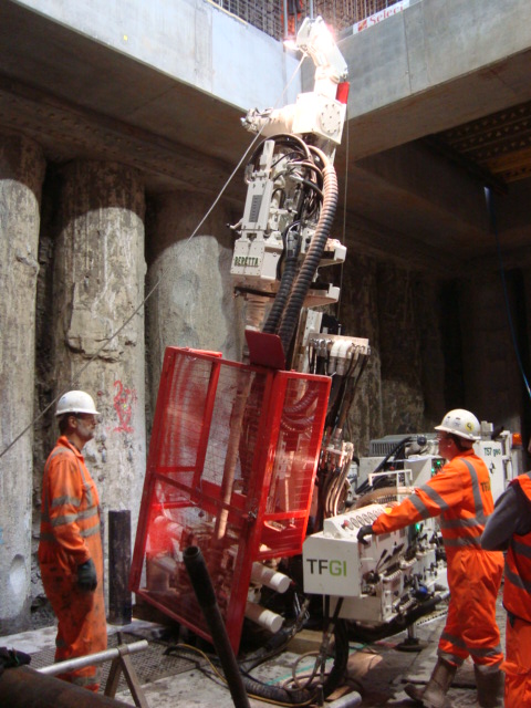
Drilling Rig. The drilling rig being used is a Berretta T 57 Geo, which usually has a 10.5 m fixed mast. Given the high strength of the soil, the possibility of pile overspill the drill and the restricted head room the drill was modified rather than use smaller drilling rig with insufficient power to penetrate the soil efficiently. In addition the drilling rig would need to be articulated in order that it could drill at an angle to allow the well tips to be outside of the pile wall. As a result the drilling rig had a smaller mast at 5.5m and hydraulic rams to adjust the drilling angle fitted, all of this was completed in Italy at the expense of C502.
Depressurisation Wells
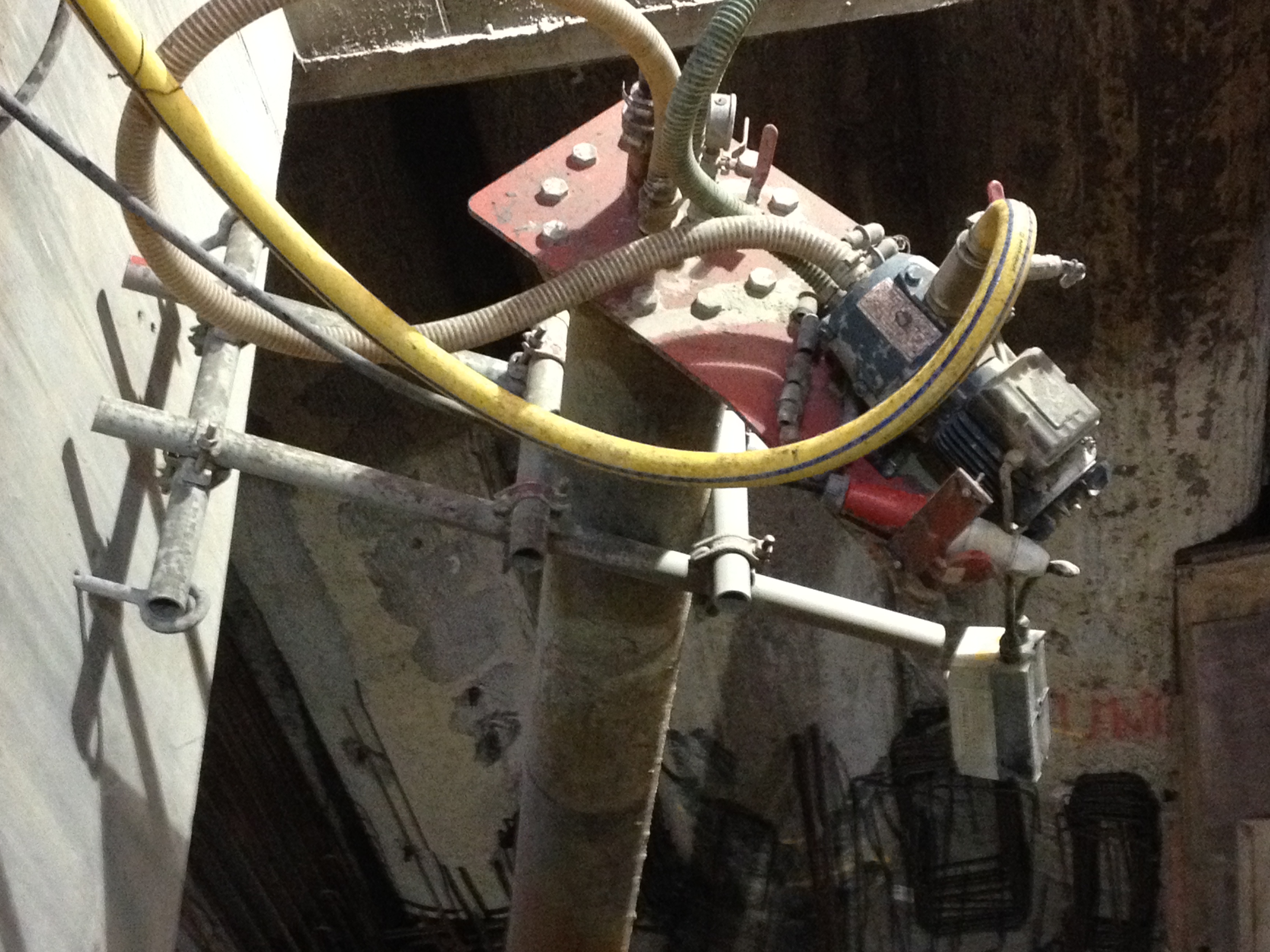
The well system being used is an ejector system that uses a vacuum to reduce the pressure within the well to set up a artificial low pressure and hydraulic gradient which is intended to draw the porewater from the soil and reduce the pore pressure. The low permeability of the soil means that the seepage rate of the soil is not sufficient to lower the porewater pressure to the required levels set by C138. Unlike an air induced vacuum as used on deep well systems the ejector system induces a vacuum by pumping water into the ejector well tip which sets up a venturi vacuum. The amount of water that is extracted must account for the water pump through the ejector to set up the ventral vacuum.
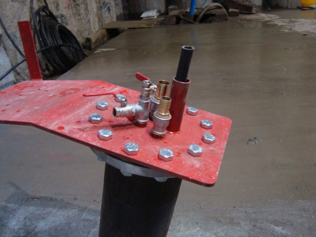
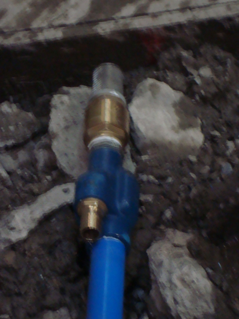
Pictures Right to Left, Well head showoing water inlet and outlet, ejector pump head, water injected through left connection, water removed from main blue pipe.
Drilling Operation.
Angle of Attack. In order to place the wells outside of the pile wall we determined the end location of the wells at 65m, and the location of the C510 running tunnels at 72/73m. This gave us a angle of between 15-20o and at a distance of 2.2m from the pile face.
Drill Setup. As the engineer overseeing the drilling I have been setting up the drilling points and then confirming the drill is at the correct angle prior to drilling. This has been done by using the EDM to determine the Easting and Height of two points on the mast, then using Trig to determine the angle of the mast.
Drilling speed . The speed of drilling is governed not by how fast the drill can be forced through the soil but how quickly the cuttings can be cleared from the well. The drill uses a drilling tip and drilling rods using drilling mud to bring the cuttings to the surface, not an auger.
Drilling Mud. Drilling mud is a mixture of water and additive to create watery slurry. The type of additive used is dependent on the soil type. The drilling mud acts as; a lubricant for the drilling tip, as a well filler similar to bentonite to maintain horizontal pressure to keep the well open and as medium to carry the cuttings clear of the well. Drilling mud is pumped through the centre of the drilling string to the tip, it then picks up cuttings and is forced to the surface. The drilling mud then passes through a series of settlement tanks and then recycled. The types of addictive for different soil types are not an area that I have a great deal of information at this time.
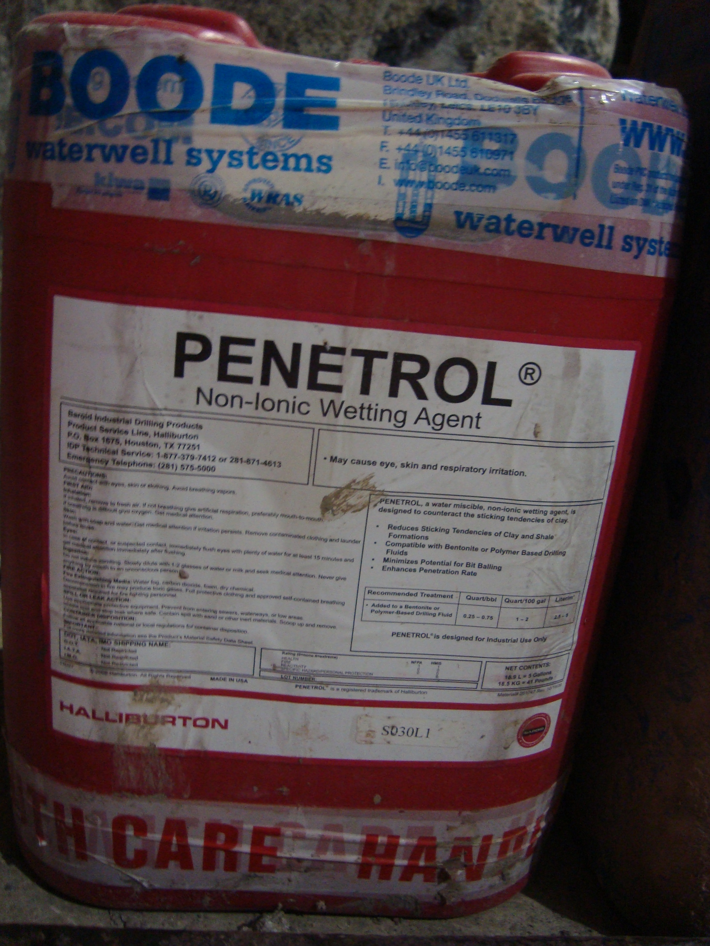

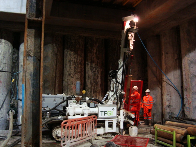
Pictures Right to Left, Drililng mud additive, Drilling rig set at 15 degrees, drilling rig
Understanding the risk in depressurisation well design
Blomfield Box Depressurisation Design.
Situation General. A review of the ground water monitoring was carried out earlier this month by the design authority (Mott McDonald) following concerns raised over the effectiveness of the current and the future depressurisation designs proposed by the primary contractor (Laing O’Rourke). The design authority highlighted its concerns over the proposed equipment and methods to be used to depressurise the sand and silt layers within the Lambeth Group of soils, on which London and much of the South East of the UK based.
Ground Investigation. There wasn’t one. Prior to ground works commencing on site the site was occupied by a building. The handover of the site was delayed. On the handover of site piling works commenced and no site specific ground investigation was completed, considered to be a luxury rather than necessity given the delays already against the programme and the potential financial implications of further programme delays. Despite the lack of a ground investigation the ground was assessed and has subsequently been proven during the excavation to follow the form typical for London Clay overlying the Lambeth Group of soils.
Engineering Risk .In the case of C502, the engineering risk is not asses to be the ingress of water to the excavation but the risk is due to the high pore pressure within the soil increasing the risk of base heave at the base of the excavation and shear failure of the exposed soil between the contiguous pile wall. In order to design against this risk the requirement is reduce the pore water pressure in order to increase the effective stress and thus the strength of the soil at the base of the excavation. Whereas water ingress is a property of a high permeability soil, high pore water pressure is a result of low permeability soil and as such the two conditions require different well designs to address the riskAdditional risks are identified as programme delays whilst works are halted pending the approval and implementation of an appropriate depressurisation system.
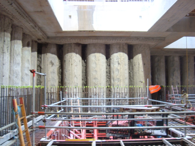
Contiguous pile wall with gaps exposing soil.
Current Depressurisation. The C502 contract and site (Liverpool Street) is in close proximity to the running tunnels being constructed adjacent and beneath the C502 site by the C510 contract. The nature of tunnelling has required C510 to have carried out depressurisation of the ground and since Aug 2013 C510 have been pumping at a rate of 300 to 600 l/hour from a system of ejector well points. The well points have been located in the sand / silt horizons identified during the C510 ground investigation. The ground investigation had shown that the pore water pressure was above the accepted levels specified by Crossrail. Following pumping by C510 the pore water pressure was demonstrated to have been reduced through the monitoring of a network of piezometors. In contrast C502 had adopted a deep large diameter well system with submersible pumps that are situated beneath the sand and silt layers within the Lambeth group of soils and have only achieved 100 to 200 per day. The two concerns that have been raised are:
1. C502 does not appear to have taken into account the effect of the depressurisation effect of the C510 ejector pump system in artificially lowering the pore water pressure. On completion of the running tunnels parallel to the C502 site, C502 will no longer be able to rely on the effects of C510 pumping.
2. The use of submersible pumps within the Lambeth group of soils will not be efficient enough in lowering the pore water pressure to within the acceptable levels due to the low permeability of the sands and silts.
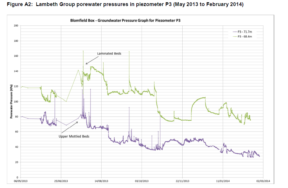
In the case of C502, I have assessed that the current depressurisation system that has been employed is not appropriate for addressing the actual risk posed to the project. The above graph clearly shows the impact of the c510 ejector pumps on the porewater pressure with a steady decline in the pressure, althoug it still remains above the Amber levels set by Crossrail. Over the period of Dec 13 C510 stopped pumping during a pause in works. Over this period C502 continued to pump however the porewater pressure rapidly rose within the laminated beds. Then steadily reduced once C510 recommenced pumping, but still remaining aboe the amber levels. This is clear evidence that the current well design is insufficient to address the risk of high porewater pressure.
Well Design. Although further research is required to understand the details of the plethora of different well systems available currently, it is important to ensure that the correct system is employed to address the identified risk. The systems can loosely be categorised as Deep Well system or Vacuum assisted systems
Vacuum Assisted Wells. The basic principle of a vacuum system is that by generating a vacuum within the well an area of low pressure is formed which in turn lowers the porewater pressure. These systems are best employed in soils of low permeability in which pore water does not freely flow and must be drawn out of the soil to lower the overall porewater pressure.
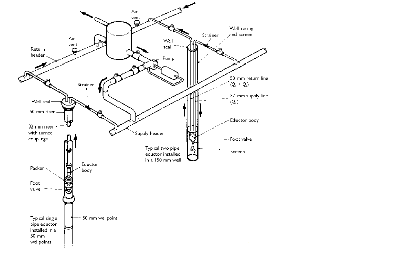
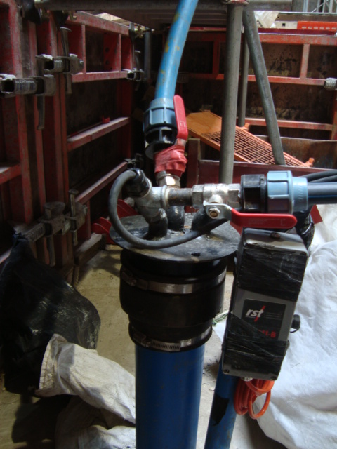

Diagram showing layout of vacuum well system & Onsite Vacuum well
Submersible Pump Wells. A submersible large diameter well relies on a high permeability soil to create an area of low pressure and to establish a hydraulic gradient. These well systems are suited to high water flow and are used to address the risk of ground water ingress to a site.
Diagram showing submersible well system
Conclusion The publication of a report from Crossrail that has required C502 to revise their depressurisation system has caused a level of disagreement on site with many of the engineers seemingly missing what the actual risk. There appears to be a common misconception amongst the site engineers that high volumes of ground water ar symptomatic of high pore water pressure and the risk of base heave. As a result many do not share the Crossrail concerns of high pore pressure posing the risk of base heave and are appose to utilising a vacuum system that will delay the programme and cost ultimately more to install and run.
I can hear Johns words once again” never assume anyone really knows what they are talking about”
Engineering is not the only risk.
Situation.
The northern wall of the Blomfield Box Superstructure runs parallel to the London Underground District line. A heavy duty fence had been erected to provide the required barrier between the two sites and to protect both personnel working on site and trains from construction activity. Concerns over safety and constructability of the current design of an insitu RC wall and aluminium rain screen cladding.
Build-ability: With the heavy duty hording in place there is no means to access the other side of any formwork to strike the formwork once the concrete has been poured. Left in place form work was looked at to overcome this issue but the issue of affixing the rain screen cladding would still be a problem.
H&S: In order to construct the rc wall and cladding access from the track side would be required to erect formwork and to fix the rain screen. Due to the live track this would only be achievable during engineering hours (0100-0500 daily) during which time the track is in places still live other than those sections that work is taking place.
Commercial: The closure of the line and works completed during engineering hours is very expensive with cost payable to both London Underground for line closure and in overtime for the Laing O’Rourke operatives. It would also have a knock on effect of additional labour cost as those working over night would not be available to work the next day shift, therefore additional operatives required to ensure the day work is not affected.
The proposed solution was to use a precast concrete cladding section that could be lowered into place and fixed from the inside to remove the problem of live track side working and to reduce the need to work in engineering hours. The requirement for the precast is as per the Project Managers Instruction below:
1 Change the cladding arrangement at Blomfield Box North Elevation from the current “aluminium rain
screen on RC/ Blockwork substrate”, to single skin Pre Cast concrete plank spanning vertically as per
a. Liaise with C138 – Peter Churton, and agree: 1) Loading; 2) Fixing restraint requirements; 3) Any
changes required to the concrete profiles; all to be subsequently recorded and agreed in an ICD.
b. Design, detail, manufacture and install cladding in such a manner that the works can be achieved
without the need for temporary access/disruptions to the railway face of the building.
c. The joints in the PC planks to be detailed with solid mortar/ grout infill with adjacent planks locked
together by interlocking rebar detail, generally as provisionally agreed with C138/ CRL during visit to
Explore this winter.
The issue that has now arisen is that the PMI was issued having not consulted all departments and has been to constraining in its direction and has resulted in a period of abortive works that have subsequently lead to compensation proceedings.
The new issues:
Non Structural: the precast wall is now to be a cladding/fascade and not a structural wall. This means all connections must not become load pathways and load the wall. As the superstructure will now be acting as canterlever and we have been told to assume a 20mm deflection the connections must be flexible enough to account for this.
Fixed grout connections: The connections have been stipulated as grouted. This has given us a number of issues: Firstly the grouting of joints means that there will be no flexibility in the joints, therefore the panels will need to be stacked on top of each other and that the 20mm deflection will need to be accounted for in the connection between the superstructure and the precast panel and not between the panels themselves. Secondly the purpose of using precast panels was to remove the requirement to access from the LU live track side. The use of grout to seal the connections still requires some form work to prevent the grout flowing out of the connection during pouring and then the form work would have to be struck from the track side.
Architecture and planning: the accepted precast drawings by the architects and the planners show the precast panels fixed externally to the superstructure. This however requires that the precast panels are fixed to the original rc wall location as there is no structural plinth directly at the base of the precast panels new location.
Heavy duty fence line: Having set off down a proposed method of affixing the precast panels to the superstructure and having though we had resolved the structural and architectural issues I thought I would just check the fence alignment. One survey and painful lesson in using AutoCad I discovered that the space between the heavy duty fence and the precast panels would only leave 40mm of space in which to manoeuvre the panels into place. Time spent in reconnaissance and all that….In during my investigation of the heavy duty fence line I raised concerns that should we proceed with installing any wall be it RC or Precast once fixed in place there would not be room between the electrical cable rails and the new wall to access the fence to allow for its removal. As a result the fence would become a permanent feature. This I knew to be unacceptable to LU.
M&E: The show stopper however has come in the form of permanent services. The original design of the services was hard against the RC wall. The new precast panels once fixed external to the superstructure would only leave 200mm gap. This presents a maintenance issue as the connections would have to be exposed in order to account for any deflection and would therefore require inspection and maintenance. Having raised this with Crossrail and that we would need alterations to the M&E it soon transpired that this was not possible without incurring huge redesign costs. IN addition the possibility to use access hatches through the M&E ducts to conduct future inspections and maintenance would also cause large commercial issue in the future. The ducting is to be used to provide ventilation to the shaft, station platform and running tunnels. Any interruption to the ventilation would result in the closure of the station. As a commercial business this requirement for periodic station closure to maintain the precast panel connections is not acceptable by Crossrail.
Conclusion:This fire and forget approach is becoming a bit of a theme on site with departments and individuals reacting to issues and concerns raised without fully working through the consequences. While in this case it was for us to resolve the issue the constraints placed on the changes allowed little room for manoeuvre. After all the design changes and arguments over the structural design of the panels and waterproof connections the elephant it the room turned out to be the heavy duty fencing. Originally proposed as a means to avoid live track side works the precast panels still require the fence to be removed and this can only be done live track side.
We are back to square one, the PMI has been retracted and we have been instructed to now propose a new solution or accept the original designs and the risk that are associated with this. The abortive works that have been completed have now been passed to the commercial team to proceed with compensation proceedings against Crossrail and all for a getting out of the office and fully understanding the situation on the ground. This episode harks back to John and his lessons on retaining walls in that the designs only show the wall in place but if temporary situation won’t allow you the path to the permanent state then you may need to rethink the permanent state. And a lesson from myself in that sometimes the temporary and permanent conditions must consider not only the engineering risk but also the commercial and other department risks.
Not playing nice….
As part of the Liverpool street station the northern wall of the Blomfield box which will create the interface between the Blomfield superstructure and the London Underground (LU) Circle and District line was due to be an RC pour insitu wall with aluminium rain screen cladding. Well not any more. Following extensive campaigning by Laing O’Rourke since 2012 to produce this wall in precast and countless rejections Crossrail finally agreed to completing the wall in precast concrete, however this has left Laing O’Rourke only 4 weeks in which to turn the designs around in time for the next design review which is critical to the 3D modelling.
The Issue.
Build-ability. The original wall and cladding were due to form the interface between the LU and the permanent structure of the Blomfield Vent Relief Shaft. Between the LU and the construction site is a temporary heavy duty hording. The space between the hording and the back of the RC wall was only 350-400mm, which given the size of the form work sections required to pour it would prove difficult to fix in place and even harder to then remove.
H&S. The only means to remove the formwork would be to remove the heavy duty hording. This presented a considerable H&S concern due to working next to live track.
Commercial. Working track side could only be achieved during track closure (engineering hours, 0200-0500). Working during engineering hours would present considerable time constraints and incur additional cost.
The Proposal.
Replace the RC wall with a precast twin wall. Precast twin wall could be constructed off site and the lowered into place reducing construction time and also negating the need to work track side (when constructing the wall). The overall cost for the wall could be reduced with reduced working hours, reduced transport cost of only transporting the twin wall rather than rebar deliveries and concrete pouring deliveries.
The Actual Project managers instruction
The RC wall and cladding are both to be replaced by architectural grade single skin precast wall. Of which LOR are to take design responsibility (actual instruction a little more indetail)
Having been given the responsibility to deliver the precast facade as it is now known as it is doing the job and the cladding but is not structural I have become embroiled in the dirty world of commercial and design responsibility. While i have very little engineering input with respect to design the facade for loading but I have all the responsibility of coordinating the effort of the architects and engineers from Crossrail, LOR and Arup. Lessons learnt to date.
Open to Interpretation. The PMI was written in such a way that Crossrail believe that it allows us the scope to think outside of the box and come up with our own design. As LOR do not have in house architects or detailed design teams we have had to employee Arup to complete architect designs while LOR would use its subsidiary company ‘Expanded’ to complete structural designs of the precast facade panels. The vagueness of the PMI has resulted in each stakeholders understanding of what is required being different and therefore what the facade is suppose to achieve what loads if any it is to carry and how it will look.
Design responsibility. The vagueness of the PMI has also resulted in endless wrangling over who owns what design responsibility. The architects claiming that they cant design the facade overall appearance unless they know how it is to be constructed fixed and loads transferred to the superstructure and the engineers from Explore claim that until they know how the facade is to interface with the superstructure they can’t design the internal rebar and how the loads are to be carried. At present there is no clause in any contract apportioning design responsibility either in the Crossrail contract, the PMI or the LOR to Arup subcontract. Until this is assigned then designs will not progress.
Ground Truth. The discussions were further stalled by the realisation that the as built drawings that were being worked to by the architects from Arup and engineers from Explore were in fact wrong. This was only picked up during a meeting when I noticed that the drawings that were being used and assumed did not match with my knowledge of ground truth. Lesson here always check that as built actually reflect what has been built and not what people want others to believe has been built to avoid penalties.
Commercial Knowledge. As John has often stated do not assume that others know what they are taking about. This goes for contracts as much as engineering principles. Members from the Crossrail team had been stating a claim that I found out later to be false; Cross rail claimed that Laing O’Rourke were responsible for removing the heavy duty hording. This turned out to not be in the scope of works and is important as it removes the problem of removing a concrete plinth that would once expose a section of the superstructure not covered by cladding. Not the end of the world structurally but for Crossrail and the architects a disaster. As we do not need to remove it the problem of extending the facade beyond the concrete plinth goes away.
Relationships RA and foresight. There appears to be an approach in the industry that its not my problem i don’t need to consider it. The original proposal state a twin wall to replace only the RC wall on H&S grounds and build-ability grounds. When the PMI was issued complaints were made that it was not inline with the proposal, however the engineers and construction managers (who are the guardians of RAs) had failed to note that simply replacing the RC wall did not remove the risk posed to a further sub contractor who would then be required to install the aluminium rains screen cladding. This should have been picked up at the design stage but then again by LOR. If the risk is too great for your own work force why pass on the risk to a further organisation, why not eliminate the risk for all. The replacement of the RC wall and aluminium rain screen with the single precast facade does just this.
Conclusion
The whole contractor, designer and client relationship is crucial and I am not convinced that many in the industry understand that. A client and their designers must make use of ground truths and experience from the coal face as much as the coalface must understand the designers and clients intent. When designs change and there is an opportunity to pass the buck to someone else people will take it, and architect and engineers just aren’t capable of playing nice.
