Archive
Charity Engineering Development
Early in my in my attachment volunteered to take part in a charity cycle ride from London to Paris, of course wanting to prove my physical prowess I instantly said yes with little knowledge of really how far it was or what the charity did. The weekend just gone was the date set for the cycle ride and I’m pleased to say the team of carefully selected office athletes set of from outside of Liverpool street station on Friday morning and arrived under the Eiffel tower late Sunday afternoon. Having now completed the cycle ride and having hounded others within the office for sponsorship I thought I better really understand what it was i raised money for, i knew it was for third world development but what was the money actually for…
The charity is called Engineers For Overseas Development (EFOD) and is a voluntary organisation that aims to enhances the training of young professionals by challenging them to deliver development projects overseas. Over the last 13 years EFOD have delivered a diverse number of projects to communities in central Africa (Uganda, Zambia and Ghana) .
Examples of past projects include:
• A medical waste incinerator at Kumi Hospital, Uganda (EFOD North-West);
• The design and construction of a footbridge over the Kanakantapa river in Zambia (EFOD Wales);
• The Sewing School in Kpone Saduasi, Ghana (EFOD South-West); and
• A community centre for a women’s co-operative farming group in Koutulai, Uganda (EFOD West Midlands).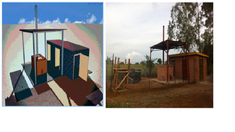
Designed and Completed Incinerator, Kumi Hospital
This year’s project is the improvement of infrastructure critical to the running of a hospital in Kuma, Uganda. The scope of the project for 2014 is; to improve the water pump, currently a broken diesel pump, to improve supply to the hospital, construction of more sustainable and hygienic latrines, improving the laundry facilities within the hospital.
The projects looks to utilise and practice junior engineers in applying engineering principles to design both structures and M&E services. The junior engineers are also responsible for the commercial process and al other aspects of managing the project from concept through to final handover. While not all the engineers will travel to Uganda all will contribute to the project. Having had a little experience of delivering engineering projects within Kenya and Afghanistan i was asked if I might be able to assist by means of reviewing projects and imparting any advice to the junior engineers on project managing such a project.
During the two short periods that I attended with the EFOD engineers and during the review of their initial designs and concepts the key themes that I feel I helped to develop area as follows:
Sustainable – considering environmental impacts, future community needs, and the longevity of the design
Buildable – with local resources, taking into account local knowledge, available expertise and skill levels
Maintainable – using a maintenance scheme appropriate to local skills, which are strengthened through EFOD provided training
Affordable – delivering required outcomes with the funds raised
Ground reality – H&S regs will not be to the UK standards and would be very hard to enforce, therefore work with what is acceptable risk and implement measures where possible.
Stop Stop Stop
As part of the piling proprietary works we were required to remove sections of a reinforced concrete slab with the old Boradgate ticket hall. The slab level that requires breaking sits 108 SSL (street level 112 SSL) and in order to facilitate piling the substation is due to be filled with foamed concrete and clay fill. The purpose of the fill and foamed concrete is to bring the ground level up to street level in order that the piling mattress and piling rig are not working over a suspended slab with a void some 4-5m deep beneath them.
The breaking out of the sections of the 108 slab is to allow remove any obstructions to the piling that may cause the piles to kick and become misaligned. To facilitate the break out we hired a machine called a Brokk which is a small remotely operated breaker and excavator. The great advantage of these machines is that they are able to access confined spaces and break out areas overhead while removing the risks associated with construction workers (operative) operating within these environments. Although there remains a risk of damage to the machine, considered much less of a risk then injury or death to an operative.
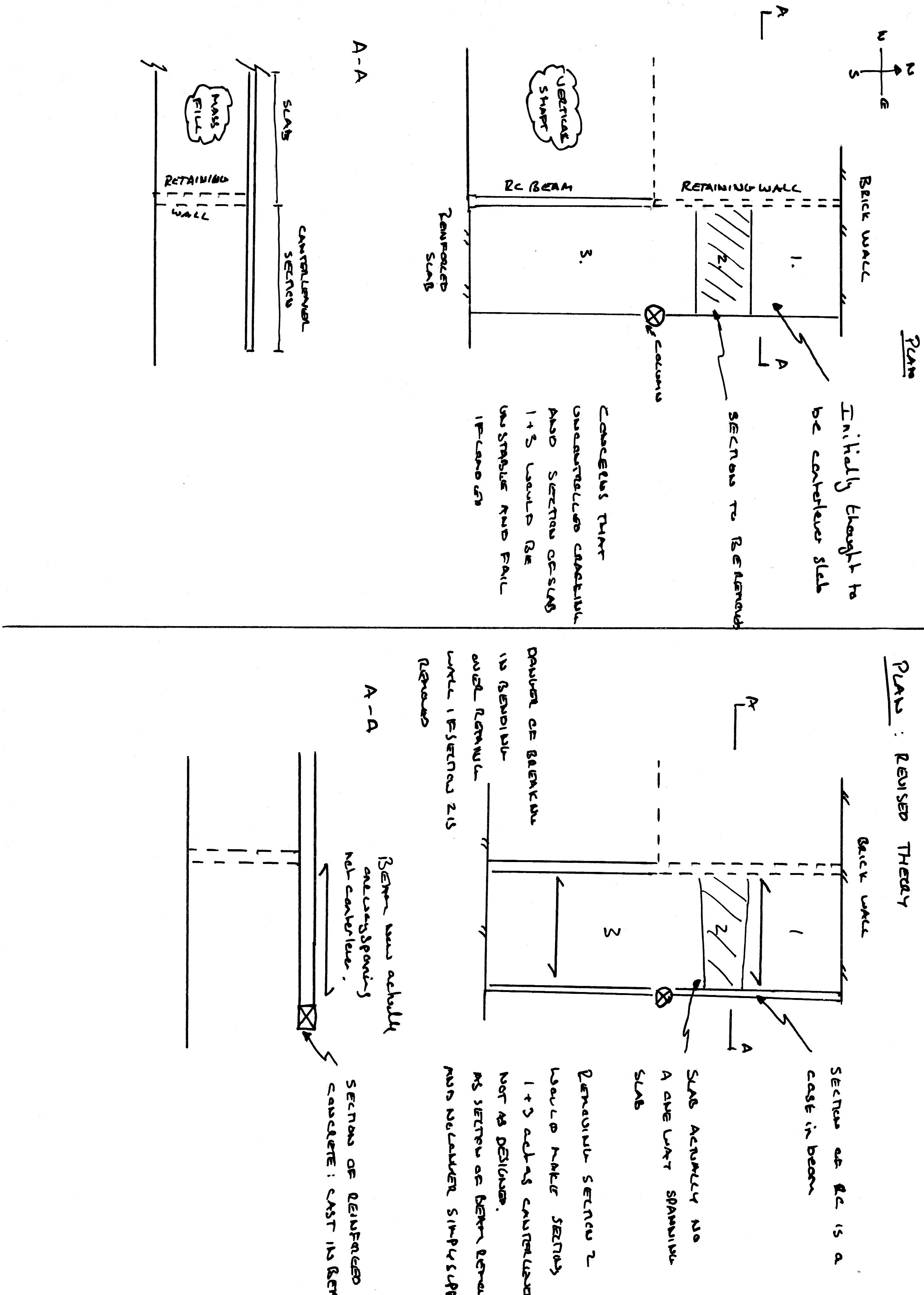
Having successfully remove all but one of the sections of the slab the project manager was pushing to remove the final section but I raised a concern over it appearing to be a canter leaver slab and that we had no way of knowing how the remaining part of the canter lever slab would react to a section being removed. Warnings ignored our project manager continued to push forward with the break out and I found myself with only a limited amount of time to come up with a convincing argument as to why we should not break the slab and an alternative solution.
The area of slab to be removed as a 1.5 x 1.5m section. The section of slab appears to be cantilevered over a small retaining wall with the canter lever wall reaching west to east. The area that appeared to be canter levered is tied into a brick wall at the northern end and then merely sits on top of the connecting flange of a cast iron column at mid-section and then tied into a reinforced concrete slab at the southern end. Between the Column and the northern wall there is only one small supporting strut. Between the column and the southern end the small retaining wall ceases and a vertical shaft opens beneath the slab. My concern was/is that the breaking out of the section would/could result in unpredictable cracking and the failure of the slab presenting a risk of injury or death if loaded. A phone call to the rear guard for some further advice deduced the following:
The area that at first appears to be acting as a canter lever may in fact be acting as a simply supported slab, with hidden cast in beam that spans from the northern wall to the column and then to the southern slab. This would then allow for a one way spanning slab from the retaining wall to the beam. If this is the case then removing a section of the slab would then make the slab work in a way it was not design too with the potential to fail un predictable if loaded. This is of course only a theory, as I have no way of knowing if the edge of the slab is indeed a simply supported beam and I also do not know the make up of the steel with in the slab.
Initial recommendations:
- Remove a larger section of the slab to the north of the column. This would then allow the southern section to act in isolation. Any area north of the column that may have been unsupported and pose a risk of unpredictable failure would be removed.
- Find another way of completing the work.
Final solution:
As a further part of the works we are required to fill the void beneath the 108 slab with foamed concrete. By filling the void first and then breaking out the section of the 108 slab the risk of failure has been completely removed. The order for the works is not important as neither the foamed concrete nor the break out are dependent on the other.
In the words of the great orator “never assume anyone else knows what they are doing” in this case after presenting my theories and recommendations and with no one else having either come up with a recommendation or even being able to prove me wrong we were forced into working to my recommendation. So I hope it all works. May I recommend that should any of you find yourselves in the future be travelling on Crossrail, I recommend that you do not get off at Liverpool street as i have hand in guiding the build…
Rejected concrete
Saturday 3rd May has become a dark day on the progress of the Liverpool street station. Following on from the success of the level 106 slab the level 101 slab should have been more straight forward. The amount of concrete to be poured for the 101 level was calculated at 220m3 which was 100m3 less than the 106 level. In addition the steel fixers had work extra shifts to ensure that all the steel was in place prior to the pour, the 106 level had seen steel fixers completing the steel as the concrete was being poured.
With all this in place the pour should have taken only six hours however 8hrs after starting, the pour was not complete. The principle delay to the pour was due to the poor standard of concrete that arrived at site and a miscalculation in the quantity required, with a further 7 loads having to ordered.
At the pre pour meeting on the Friday I had raised my concern over the fact that the previous pour had seen concrete being pumped into form work before the slump tests were complete. If any of the slump test had failed dramatically we would have had severe difficulties in removing the failed concrete or even identifying were it had been poured. In my mind this would have meant the entire slab would have not met the required strength. With my concerns aired I found myself armed with the clip board and in charge of the slump test. Unfortunately this would result in me being struck of many a Christmas card list. The concrete supplier, Cemex, had won the contract based on price. Although I don’t have the exact contract comparison details, I have been informed that Cemex use their own brand of additives to keep cost down however this would seem to have disastrous consequences on their mix.
The concrete specified was a C50/60 mix and the slump was specified between 580 – 620 average diameters. The first delivery of the day managed a less than impressive 520mm. A discussion with the site engineer saw the concrete accepted. However the second delivery spilled off the slump testing board managing a estimated diameter of 680-700mm. Further discussion with the site engineer and the Cemex technician saw the concrete accepted with promises of improvements in the mix. However this inconsistency was set to continue and of 34 loads (full load 7.6m3) of concrete on order I ended up rejecting 6 loads with the majority of the remaining loads being highly questionable. Many of the questionable loads that were accepted were overly loose rather than stiff. Despite failing the slump test they were accepted on the basis of perceived risk of the concrete reaching the required strength against the risk of creating a cold joint.
A cold joint is formed when the time between concrete loads is sufficient to allow the curing of the poured concrete to be different to that of the next load, ultimately creating a concrete joint. As the position of this joint can’t be controlled this can result in a weakness as this may be at a steel reinforcement lap joint or an area of steel without the required anchorage to achieve the required tensile stress.
The risk was transferred to Cemex with verbal and written confirmation that the concrete will reach the required strength. Despite this reassurance from Cemex this does not sit easy in my mind as the question that was not addressed was whether the concrete strength would be reached in time to allow us to strike the formwork and then to excavate.
In addition to the structural issues the loose concrete also prevented the power floating of the surface to achieve the required smooth finish. Power floating requires the concrete to be firm enough to be stood on with enough flex to allow the power float to smooth the surface. Three hours after completing the pour the concrete was to loose to power float and a paddle finish had to be used to complete.
This has thrown up a number of contractual issues concerning the strength and finish of the concrete. The concrete was required to meet 30Mpa cube strength in 24hrs, however this took over 48hrs to achieve. The delay has had the knock on result of delaying the excavation through the 101 level to the 95 level. With over 3000m3 of soil to remove the two week excavation to working level is now going to be very tight with very little scope for further delays due to unforeseen ground conditions. The finish surface of the concrete is to be exposed the paddle finish applied as power floating could not be achieved has had to be raised a s a ‘Non Compliance Report’ and negotiations with the client and designers have continued throughout the week to seek a resolution and to avoid arbitration.
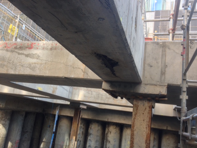
Concrete beam supported on 26mm bar……WHAT??
Having been working on the RC detailing drawings it wasn’t until I saw the shear quantity of steel and the congestion that I realised the magnitude of the work faced by the steel fixers. I noticed too that the interface between the pile s and the ring beam was by a poxey couple of 26mm bars. This has got me thinking that the next level of concrete is not held up by the connection between the piles and the ring beam.
In this case my thoughts are that the ring beam is in fact a whaler beam and the intermediate beams are acting as props. In this case the whaler beams are being loaded by the deformation of the piles and is acting like a compression ring. The load is then transferred into the beams axially loading them and putting them in to compression rather then acting as first thought purely in bending.
This theory is supported by the pile shape arrays (monitoring system) clearly showing that the piles are in bending and have in fact deformed by up to 6mm in some cases. In addition when looking at the distribution of the steel through the beams the steel is fairly evenly spaced. My thoughts are that the top and bottom steel is in fact designed to act in tension and compression in order that they can be axially loaded and resist buckling upwards or downwards. All comments, thoughts and pearls always welcome.
Honey Comb Concrete
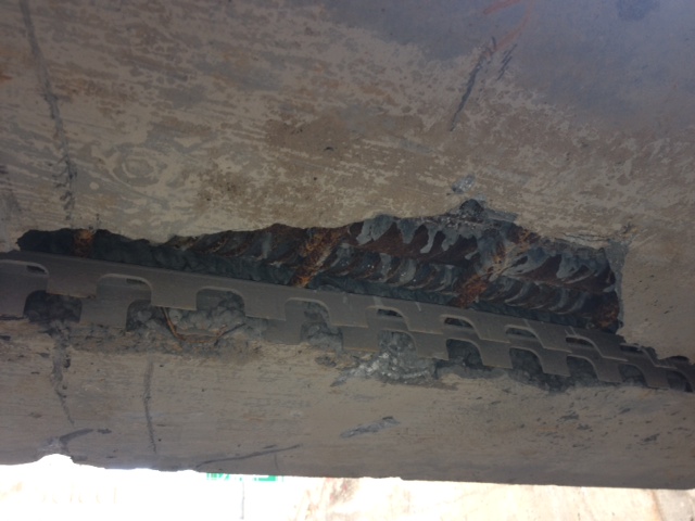
I have learnt today that this week that the term “Honey Combing” on a construction site has nothing to do with the thick sweet substance that Ryan pours on his porridge in the morning. Honey Combing is in fact the term given to poorly Lid concrete that results in voids in the finished surface of concrete.
Removing the form work during the excavation revealed a large area of steel rebar that the concrete had failed to cover. The cause was determined to be number of factors:
1. The operatives were instructed not to compact, vibrate and tamp the concrete excessively during the pour as the beam in question contained Geo Thermal pipes that were at risk of being damaged.
2. The concrete mix was not loose enough to allow it to flow around the steel to fill the void. In fact some of the slump test during the pour revelled stiffer then required concrete. The slump had been determined at an average diameter of 550mm and we had loads that varied between 650 and 400mm. The result was the expected dismissal of the concrete and a reshow for the concrete contractor it was a case of working the concrete a little harder. This was principally due to the fact that the concrete was already being pumped by the time a slump had been completed. Poor practice in my mind.
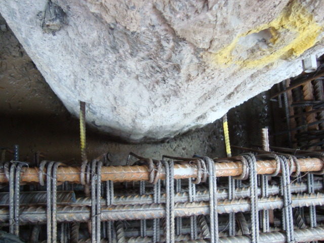
3. However ultimately I feel that pour steel fixing was the principal cause, although it is not a theory accepted among the entire site and principally not by the steel fixers. The pictures below clearly show that steel bars are packed too tightly and have prevented any concrete from passing between the bars to fill the void. The steel should in fact be lapped one bar on top of the other with the use of a cranked bar. In this case the bars were allowed to lie next to each other.
The upshot of all of this has been not and engineering problem more of a contractual problem. The making good of this void would seem fairly straight forward. The use of a fast setting cementitous mortar although it must reach the same strength or better then the surrounding concrete. My fag packet engineering behind why I feel this is a minor engineering issue is that the missing area of concrete is in fact only cover concrete and that the concrete within this region is concrete in tension with and in fact it is the steel that is carrying the load. Given that the beam is a rectangular section the area of concrete that could be removed would be half the depth of the concrete as all below the centroid would be in tension. The greater issue is that this section is typical in terms of steel across the site. A more worrying concern is that there may be more voids that can’t be seen. If a void is within the compressive section of the beam, typically here it would be the upper half of the beams, this would significantly reduce the load that could be carried across the beams. The quality control during the steel fixing was fairly stringent and while most of the team on site are confident that there would not be any further voids I looked into how one might determine if there were any further voids . The solution that I had come up with was the use of a ground penetrating radar. These appear to be fairly available for hire by many companies on line and are a very simple non invasive method of detection. Unfortunately the confidence of the team and the reluctance of the expense and delays to the programme means that we won’t be playing with any GPR systems and a non compliance report has been raised, once the making good has been completed the case will be closed.
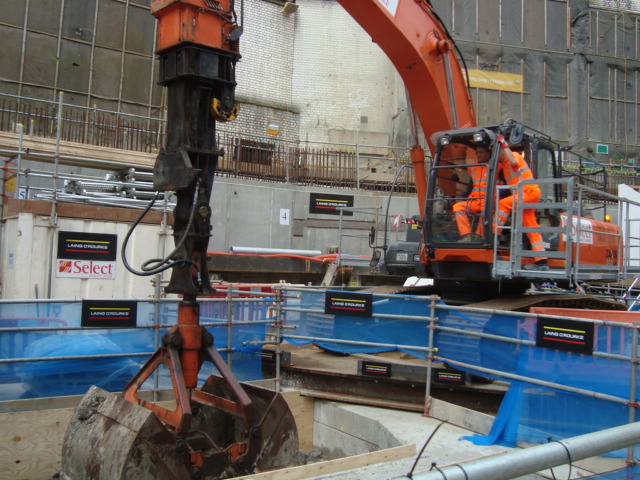
Concrete Bicuits and Big Cheeses
Monday began with the breaking ground ceremony with a veritable smorgasbord of big cheeses in attendance all vying to be in the seat of the clamshell excavator for the corporate picture. When instructed to put up “loads of signs” on the site the lads took this to the extreme and I invite you to count the number of Lain O’Rourke signs in the picture.
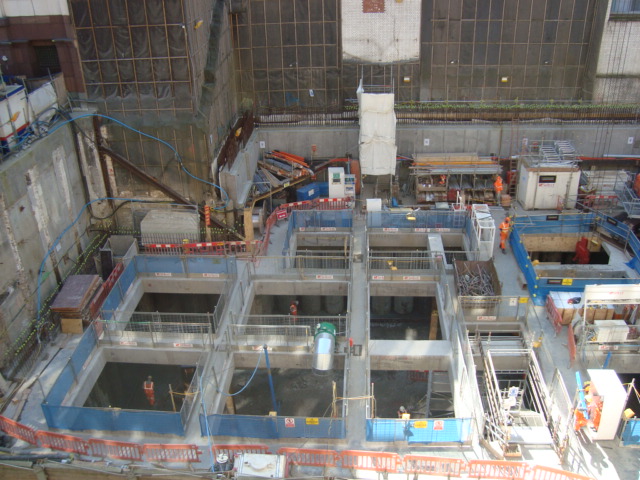
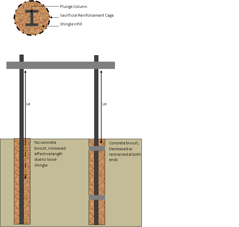
I feel it is probably an appropriate time to explain the construction method and some issues that I/we will face with the construction. The Blomfield box is a top down build. In this case a contiguous pile wall has been augured and poured to a depth of 70ish metres. The first main slab was poured two weeks ago and we are now excavating beneath the slab. Each subsequent slab and excavation will be complete in the same sequence; excavate, pour working surface, fabricate reinforcement cages, pour concrete slab and beams and then excavate through and beneath to the next level. No columns or walls will be constructed until the final level is completed at the 71SSL. All walls and columns will then be constructed working backwards towards the surface. As a result the slab and beams are required to span a gap of 25-30m in places. With no columns or walls beneath the beams the entire slab will be in tension throughout the duration of the excavation. In order to reduce the span steel plunge columns were cast into a steel cage and then backed filled with shingle. The 40m plunge columns act as intermediate supports for the slab during the excavation and then will be cast into concrete when the remaining walls and columns are constructed. During the excavation the steel plunge columns are to be exposed and are then at risk of becoming slender columns and buckling. In order to overcome this two mitigation methods have been applied firstly the max load on the slab has been limited to 5kPa and secondly the steel columns have had concrete biscuits cast in to reduce their effective length during excavation.
The drawing below shows each level of excavation, approximately 6-7m and the columns once exposed between levels and prior to the construction of the slab are considered to be slender columns if not restrained. In order to overcome the problem that over excavation and to ensure the column is restrained concrete biscuits 1200mm deep were cast around the plunge column thus reducing the effective length and making the columns stocky. Problem solved.
Opps it don’t fit!
This week I have been treated to a short city break to Birmingham to attend the in house 3 day Lain O’Rourke surveying course. The course was an excellent opportunity to brush up on surveying knowledge and proved to be more challenging then I first thought and it has helped to cement in my mind that surveying needs to be taught over a greater period then is afforded to Margret and her team in the PET course programme. Whilst much of the theory is understood by many on the course the practical application and use of a total station is a little less well understood. I would even go as far to say non existent as I struggled to find the big red on button on the latest version of the Leica total stations we were using. Having found the on button and now successfully navigated myself around the menu system I feel a little more confident in the use of a total station but a skill I fear will easily be lost if not put to use fairly quickly.
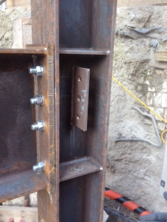
On returning to Liverpool street on Thursday I was faced with an issue of buildabiltiy. A steel structure designed to be robust and provide protection to personnel operating within its perimeter from incensed plant operators swing excavator buckets about was in fact so robust it couldn’t be built……..WTF. It had only taken 3 months to complete the designs and have it specially fabricated by a steel structures specialist and now we were going to be defeated by our own designs.
The issue was that were two I beams connected one end plate to another’s flange the designer had incorporated two web stiffeners top and bottom. This then prevented the perpendicular I beam from being lowered into position by the web stiffener. A morning of discussions ensued during which it was discussed about removing the top stiffener and replacing it, or completely removing it. Given that the purpose of the web stiffener in is to stiffen the web against buckling due to the compression of the flange and that in this case both web stiffeners would be required. The real issue was that the detailed calcs that supported the design were less detailed than one of my design exercise calcs and no one could seem to agree on the loading that the structure would have to resist, both permanent, imposed and accidental. Prophesising over all likely laods was brought to an abrupt halt as I gazed out of the window to watch the sub contractor bending one of the columns over to allow the beam to fit. Given that time was/is against us the requirement of the web stiffener suddenly became less of an issue and we turned our attention to managing the problem, and if I remember my lecture with the great orator this could have been avoided had we managed the engineering at the start. Your thoughts please.

A little Passive and no Active Pressure
The area on site known as the grout box is due to be handed over from ourselves Laing O’Rourke working on the C502 contract to another contractor working on the c510 contract. The C510 contract is responsible for tunnelling through to the Liverpool street station ticket halls. As part of their contract they are required to carry out ground stabilisation through the use of injection grouting. The area requiring grouting is accessed from the C502 site and as a result we have been busy excavating a shaft and preparing the area for them. The grout that is to be injected behind the pile shaft wall first has to be piped into the grout box and this required the removal of a pile. The removal of the pile threw up a number of questions around the stability of the pile and ground given that it would effectively be suspended and relying on skin friction to stop it moving downwards and closing the gap. In addition and probably more importantly the pile would have no active pressure that it could use to resist the passive pressure of the soil and water behind the pile. To overcome this a reinforced concrete beam was cast into the piles to act as a whaler beam and fix the now free end of the pile. The task of organising the team to cut the pile and remove the concrete was given to the new boy (only once tea making duties were completed). After a period of scratching my head, I decided that the best means to attack the pile would be to get my old friend the diamond core drill and to stich cut the top and bottom of the pile and then to use the 3T excavator to break up the concrete in situ to then be removed in smaller pieces. First question to myself “where is the risk” and from what I could deduce it was more of a question of “where wasn’t the risk”. Working underground, confined space, removing a reinforced concrete pile section, pile failure, recent weather and ground conditions significant water ingress never mind the crushing injuries to persons operating in the shaft. As this was my first major task I felt a little military precision (oh the oxymoron) was required and not the John Moran approach of hitting everything with a stick. Following a detailed planning period during which the task was planned, risks assessed and planned out, reduced to acceptable levels and residual risk communicated, team briefs rehearsals completed the team was ready to go…. And it was then called off as C510 decided it wasn’t required.
In other news I have enclosed my fag packet calcs for those interested from the inclinometer drilling. While useful to plead my case with other engineers on site that the Heath Robinson clutch system was not sufficient I would not rely on them in court. Ultimately this proved to be a project contract and management issue as the contractor was summoned to prove calcs that proved his system worked and as he couldn’t the drilling was stopped and we have gone back out to tender for another contractor to complete the works.
Outside of work I have signed up to cycle London to Paris for some charity or other, more details to follow and I have been invited to sit on the board of a charity of a board called Engineers for Overseas development. The charity challenges young engineers to use their skills to design resource and construct a development projects overseas. The chairman felt that I might have a little bit of experience that would be useful…well you know I just might…pull up a sand bag and I’ll tell you all about it.
A Friday Hospital Pass
This week on site the steel fixers have been getting the reinforcement bar ready for the big pour this weekend. So it was hands to the pumps for a 630am start on saturday. Not to happy but a good opportunity to expand my knowledge and collection of concrete photos that only engineering pests would appreciate…Rich I will send you some copies.
The arrival of the diamond core drilling subcontractor on Friday, who I shall call Heath & Robinson caused me a little brain ache and just reminded me of my role and its not to with the guys wielding petrol saws. The issue, during the pouring of the concrete piles that form the shaft perimeter, steel tubes were cast into the pile to allow sonic testers to be lowered into the centre of the pile to test the integrity of the pile and then for inclinometers to be emplaced to monitor ground movement. During the pouring the tubes connections failed and the concrete blocked the tubes so now neither sonic testing or inclinometers may be lowered into the piles. The decision was taken to diamond core the piles to clear the blockage and having had nothing to do with the entire planning of this operation I was suddenly handed a hospital pass yesterday to approve the method statement by this morning. The method statement was sound part from one small detail which was their improvised clutch. The purpose of the clutch is to clamp the diamond cores whilst they further cores are added or removed from the drilling rig.
he proposal was to use a couple of bits of wood and threaded bar to clamp the cores, all seemed fine until I performed a “fag packet calc” (Moran 2013) to determine the vertical load that the improvised clutch had to resist being in the region of 1.5T. Cue the alarm bells!!! Not convinced that two bits of 2”x4” could resist this I decided to panic the men early in order to stall for time and to try and determine if my theory was right. Being the only person in the office who had any idea that timber calcs had many K factors that needed to be considered and that the vertical force we could potentially be facing would have to be resisted by a horizontal force that would need to generate sufficient friction to prevent the diamond cores descending to middle earth, from which I think even Bilbo and his band of merry midgets would have difficulty in retreating them. Quick phone call to Richard in the rear guard to confirm my theory and to gain further guidance and I am now set to carry out the “fag packet calcs” (to follow for those interested.) This whole episode goes to prove another of the great orator’s theories that “you should never assume anyone knows more then you” as they quite clearly don’t. To be continued…
Similar…..Only Bigger
At the end of the second week I find myself in a similar situation to Ryan as I too am now fully immersed in Cross Rail although we have yet to truly establish who’s shaft is truly bigger.
I am attached to Lain O’Rourke team working on the C502 Contract which is the construction of the Liverpool Street Station ventilation and services shaft at present but is due to expand to include the Liverpool Street and Moorgate Cross rail ticket halls in the near future. I will not repeat Ryan’s intro to the Cross Rail act but would refer you to his last blog if you are interested.
The Liverpool Street Station ventilation shaft is a top down build comprising of 12 levels over a depth of 52 metres. The shafts purpose is to provided ventilation, maintenance access to platforms for E&M services and to act as emergency access and egress from the Cross Rail tunnels.
At time of arriving on site all piling work has been completed and the capping beam had been cast. A working surface for the first mass concrete pour had been constructed and the steel fixers and carpenters were commencing fitting of the first reinforcement cages in preparation for the pouring of the first slab of the main build.
Following a comprehensive week of induction and Health and Safety last week I have finally been set to work and given the responsibility for rebar detailing for the future slabs, columns and beams as the project progresses. Key to this role is a clear understanding of the construction sequence and understanding how the various structural elements of the shaft will be tied together. Neither of which I am fully up to speed with just yet….some more reading required.
In addition I have been made responsible for a temporary shaft from which another Cross Rail will injection grout in order to stabilise the ground for tunnels that will run next to the site. At time of arrival the main slab had been poured and the excavation beneath the slab had almost been completed. First task has been to break out the concrete in the piles to find the couplers from which the bottom slab rebar will be connected. The couplers were put in place with the reinforcement cage through a bentanite slurry and then concrete poured to form the piles. It was not a surprise to discover that some of the couplers were either missing in action or misaligned. For these the concrete piles have been drilled and rebar starter bars have been resin fixed into the piles. Begs the question why not drill and resin fix all starter bars to avoid breaking out the concrete piles….answers on a post card.
