Archive
The importance of definitions
Following a few recent blogs regarding H&S incidents I thought I’d share these little cartoons we found depicting the different terminology for various incident types.
The first image seems particularly relevant for both Mark’s and Al’s recent experience with lifting equipment. From reading the blogs it sounds to me like Al’s site experienced and unsafe act when a worker was seen under an unsupported load. Mark experienced an unsafe condition (the poor slinging technique) which led to a near miss (the thing actually fell but no one was hurt).
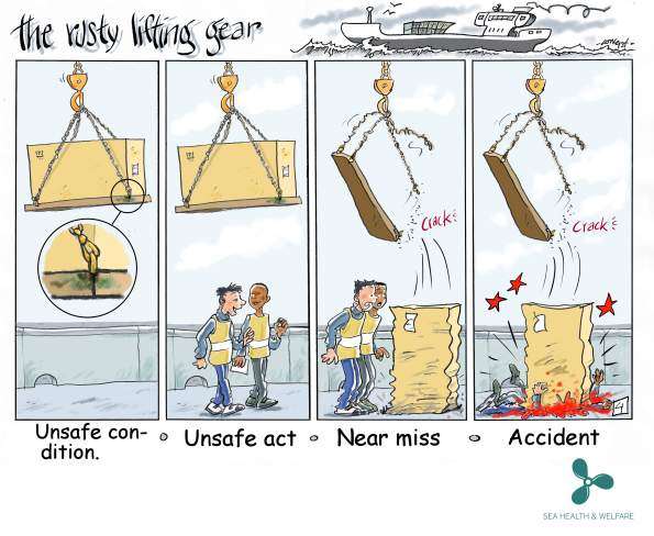
While of course all of these incident types should be properly addressed, and all have degrees of severity within them, the terminology used can be quite important.
Take, for example, our ever-troublesome scaffolders who failed to properly enforce an exclusion zone on a public-access pavement beneath their work area. They were spotted and the situation was corrected but was this a near miss? Nothing was dropped onto the pavement and no one was injured but the potential was there. This was reported as an unsafe condition (working overhead without edge protection). Had it been labelled a near miss (with the potential to impact the public) we would have had a world of problems.
This may sound like opportunistic word play but it is an important delineation. From a safety point of view it was a very serious occurrence, and was treated as such by all involved, but contractually the wording is vital, similar I suppose to John Holland’s 1P rating in addition to the strict H&S term. The irony of the situation is they were up there erecting a scaffold fan to protect pedestrians from falling objects!
A great deal of fallout resulted of course (revisiting method statements, tool box talks, safety briefings, etc) but the point of this blog was the importance of definitions in contractual communication, and not just in H&S.
Structural clash detection using 3D modelling and point cloud survey
One of the less helpful outcomes of the acrimonious handover of my site from Mace to McAlpine has proven to be the lack of accurate site condition data. Without the ability to survey the site before taking possession we have been left playing catch up on a number of important issues.
The 14 large-diameter bored piles, installed by Mace, are to receive base plates with pre-fabricated column starters and reinforcement cages. These units are limited in size by the capacity of our tower cranes but still come in at up to 18T per piece. This single unit is then to be lifted into place within the pile casing without clashing with any of the existing pile reinforcement. The plan is then to top up the concrete/grout beneath the base plate. The many risks in process can wait for another time because the first problem came with the site handover.

Revit model of the column base plate in the pile casing
On inspection of the pile heads the existing reinforcement on one of the piles was visibly wonky (technical term). This raised concerns over the global positioning of the pile, was it the rebar or the pile sleeve that was wonky, what is the design tolerance for position and verticality, which was in the right position, who surveyed it for the as-builts and how, etc, etc but the key question was simply can we get the base plate in in the right place without clashing with what is already there.
Having satisfied ourselves that the base plate would fit inside the pile sleeve we set out to identify any clashes with the rebar. In collusion with our geospacial team and BIM manager we superimposed the structural model onto a point cloud survey and ran clash detection between the two. This quickly showed the extent of our problems and has allowed for mitigation measures.

Model vs point cloud clash detection, red indicating clashes.
Of the clashes, in red on the image above, some could be removed on site (e.g. the anchors you can make out beneath the main steel shear key plates were cut down) but there was to be no damage to any of the existing pile reinforcement (the outer ring of vertical H50 bar, in grey on the image). Instead the structural engineer instructed that the base plate be re-worked off-site by cutting and re-welding the base re-bar.

Diagram showing base plate rebar to be cut and move inboard to avoid clashes.
This use of 3D modelling and clash detection software was able to identify a serious clash before the key components were delivered to site. Being as the fabricator is in Bury and the work required could not be easily done on site, this early notification prevented an expensive, time consuming and awkward clash on site.
Sustainable Generator Fuel Trials
In an effort to minimise CO2 emissions and disturbance to the local community we are trialling the use of two hydrogenated vegetable oil generators. These are required to power the tower cranes over a two week period while we move a sub-station connection and transfer from low to high voltage supply.
The ‘Green D+’ fuel is made exclusively from waste products comprising a mix of vegetable oils and animal/fish fats. Unlike regular diesel hydrogen is used as a catalyst in the process instead of methanol. This is therefore a sustainable fuel source which saves one tonne of carbon for every 350 litres of fuel burned. We are expecting to save 68.5 tonnes of carbon from this trial – equivalent to roughly 14 personal flights from London to Sydney.
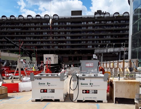
Beyond its carbon benefit, it also achieves a 29% reduction in Nitrogen Oxide (NOx) emissions and a 77% reduction in airborne particulates compared to red diesel, and therefore reduces air pollution to the local community. The high cetane value of the fuel (70+) also reduces combustion noise, sometimes referred to as ‘knocking’ noise, which is so often associated with the running of a generator on site.
Downsides are a marginal increase in cost of the fuel and the whole site smells faintly like a chip shop. But we’re saving the planet.
Environmental benefits:
- Reduction in carbon emissions
- Use of waste materials
- Reduction in noise and air pollution
Business benefits:
- Stakeholder engagement (community and City of London)
- Small trial of potentially beneficial technology
How to pile through a railway station
As we aren’t able to add pictures to the replies, this is a quick post to answer Richard’s questions about the pile heads.
First things first – the time lapse camera looks west, from the ‘back’ of the site into the narrowest end. The view in my first blog An engineer without a site… for now. shows the remnants of a considerable amount of steel. This steel was formerly a piling grillage which can be made out below.

August 2018 – piling from the grillage at 21 Moorfields
The retained deck (RD),a composite steel beam and RC deck which is both the ground floor of this site and the roof of Moorgate station, is only rated for 10kPa UDLs so could not bear the weight of piling rigs. To get these rigs on site a grillage scheme was installed (3000T of steel – more impressive temporary works!) on plinths tied into hard-points on the RD.

Piling model showing grillage, RD, rail platform, pile casing and soil strata
From this platform a steel casing was driven through the grillage, through the Moorgate platforms, through the made earth, through the gravel and into the London clay. The piles were then bored, from the grillage into the Lambeth beds, to depths of up to 57m.
The upper part of the pile acts a column through the station platform level and the casing remains in place. The piles are heavily reinforced in the upper sections in order to transfer moments imparted at the head by the base plate connections. The steel columns are fixed to the pile heads and tied into the reinforcing cage at the head.

Pile function
Moments are ultimately transferred by the piles to the ground beneath platform level as shown in the sketch above.

A smaller 1.8m diameter pile (with engineer for scale). Total 12 No 2.4m dia piles and 4 No 1.8m dia
The piles have also been fitted with fibre optic strain gauges and grout tubes. The 5×4 anchor grid (seen below) was used to connect 4 No piles as reaction piles to the test rig for preliminary testing of a 1.2m pile. Axial design load on a 2.4m pile is 58MN.

Pile reinforcement (28 No H50 longitudinal bars with H16 links at 150mm centres), fibre optics and grout tubes.
An engineer without a site… for now.
21 Moorfields will be a 17-storey office and commercial building, ear marked to become the London HQ of Deutsche Bank, in the heart of the City of London. It is a fascinating project that pushes the boundaries of light-weight steel structural design and threads the needle, in some cases quite literally, through the maze of site constraints. The project is estimated to cost upwards of £350M and is scheduled for practical completion in 2022.
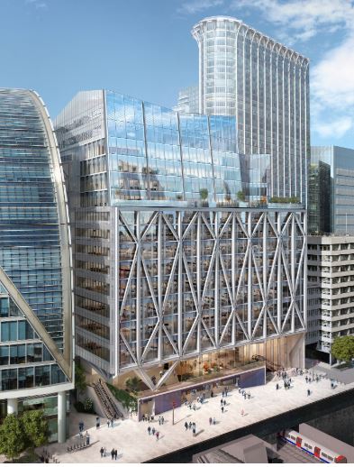
The East Face above the Crossrail station entrance
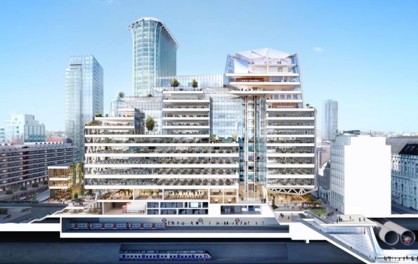
The development spans over the 6 live London Underground (LU) lines running into Moorgate Station and is immediately above the western ticket hall and access shaft for the London Liverpool Street Crossrail (CRL) station. The ‘ground floor’ of the site is also the roof of Moorgate Station and is a composite steel beam and RC slab deck supported on a series of piled columns known as the retained deck (RD).
Architects impression showing the two LU lines and the Crossrail running tunnels – piling through this lot was literally threading the needle.
The steel superstructure spans 55m across the retained deck between two parallel rows of giant piles (the largest of which is 2.5m diameter and 57m long). Each pair of piles supports a 10-storey arch and truss to span the gap with a number of temporary works stages to ensure stability of the structure through to completion.

Truss and arch system with cantilevered East Face Truss
I have been assigned to manage the superstructure concrete package, starting with the pile heads, steel base plates and mezzanine deck, moving onto deck and beam work at every level.
All very good but there is one small problem… we aren’t allowed on site.
The early works contractor (Mace), failed to secure the second-stage (i.e. superstructure) contract and so are vacating the site – slowly. Until they do so (the end of this week) we are sitting in an office down the road with only the high camera for site updates. To complicate this, the D&B contract between McAlpine’s (my lot) and the client (Land Securities) has yet to be signed so when works do start on Monday no one will be under contract to anyone else.

The closest any one can get to site until Monday
This enforced exile has given me ample opportunity to read into my works package and spend time with the QS team to fully understand their processes. I have also already experienced almost every type of contractual arrangement I can recall from PPO and PCM – we have PCSA, Letters of Intent, Contract Administrators Instructions, Frameworks and, hopefully soon, a JCT D&B contract.
Come Monday I can sharpen my stadia rod and don my finest hi-vis vest for a bit of Engineers in the Wild excitement on site. Until then I’m back to my bills and quotes, spreadsheets and delivery notes.
