Archive
Analysis Software
There’s been quite a bit of discussion recently regarding what analysis software is being used in various design offices. There are a wide range of options and the practice I am with have developed some loose guidance on which structural analysis software should be used for different design problems as outlined in the figure below.
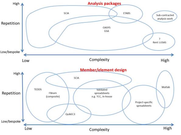
So far I have used SCIA, TEDDS and bespoke excel spreadsheets. It has been a steep learning curve to get to understand some of this software, during which time I’ve been very grateful for YouTube. There are some really great examples to follow. Expedition have also published a useful table on their internal website listing which members of staff you should speak to for advice on different packages – this has proven extremely useful.
I was initially frustrated that we use STAAD at PEW as it now seems very simplistic and doesn’t cover the complexity or design options of some of the other software. However, I think it is useful to demonstrate the process of modelling and analysis, and I suppose no matter which software you choose you can’t cover all the options. I think it may be worth looking at TEDDS if a replacement is ever sought. TEDDS for Word is very powerful and would prove useful during design exercises.
One thing that has really surprised me is the use of simpler software to check software output rather than hand calcs. It seems that there is so much familiarity and confidence in simple software like TEDDS that people are confident they won’t make the input errors. However, I don’t have that intuitive understanding of TEDDS yet so I don’t feel comfortable doing that. CIRIA technical note 133 is a useful guide to checking computer analysis.
My level of confidence with the software remains low, but this is improving as I build up an understanding of the design options that can be applied and how these change the model.
Free Champagne
So here’s the deal, the blogs recently have been pretty boring and long (thanks E&Ms). I’ve been to a couple of presentations on BIM recently and that’s also a long boring subject. I’m not likely to have to buy Champagne in the mess for any celebratory reasons in the foreseeable future so i’ll buy a bottle when we get back to Chatham for the first current STUDENT to translate all the TLA buzzwords below. Staff or former students feel free to play along separately for your own for personal pride/shame. I’m guessing this is going to be won by an E&M as this is their level of boring.
In the event of any disputes my scribbled notes are final.
PAS, CDE, PQQ, BEP, LOI, IM, CIC, EIR, LOD, MPDT, PIP, BIM.
Steel Connection Failure
I remember with joy the moments in the Phase 1 lectures when the Lecturers outline various design approaches (let’s call them easy, complicated and devilish), and then tell us to draw a line through complicated and devilish, “you’re a fool if you choose those options, we’ll focus on the simple option for this tutorial”. Brilliant news.
Looking back through my Steel connection notes this is exactly what I’ve done and all of my Ex Steel joints were designed as simple connections (i.e not moment connections). However, it’s not always possible to draw a line through the difficult options.
One of the projects I’m working on over the next few weeks is the back analysis of steel connections in a building which has experienced a failure during use (a loud bang at night as one of the connections failed). I’ve still got a lot of work to do but below are my initial musings from SCI P207/95.

Figure 1 – Failure of B33 to C13 connection
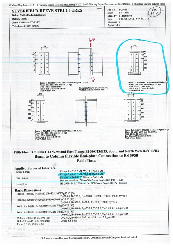
Figure 2 – Steelwork contractor calculation output
The frame was designed by my consultancy and a steelwork contractor designed the connections. The design of the connections was carried out using Masterkey software to BS 5950. The BS states that when the design is handed from a Structural Engineer to a Steelwork Contractor the contract documents and design drawings must adequately define the design requirement for the connections. Further guidance within the National Structural Steelwork Specification for Building Construction states this information should include:
- Design concept
- Member schedule and drawings
- Design standard to be used – in this case BS 5950
- Forces, moments and combinations at each connection – some raking/angled beams also have an axial force to consider.
- Factored or unfactored loads used
- Restrictions on joint details
My task is to back analyse the connections designed by the Steelwork Contractor, using the same software in order to check their connections for revised actions. The reason the actions have been revised is because regardless of whether the connections were designed as simple or moment connections (the two simpler design approaches), the reality is that there will be a degree of deformation at the connection, therefore the joint will really be acting as semi rigid with some degree of rotational deformation. If the connections is partially deforming then part of the moment will be transferred into the adjacent beam, in the case of a double beam to column connection, and part into the column.

Figure 3 – Classification of moment connections as per SCI P207/95
Initial investigations have shown that some of the “simple” connections may be too robust to act as a simple connection, and will in reality transfer some of the moment through the connection. Take note McClure – you shouldn’t always go big early.
Temporary Works Inspections
The Temporary Works Design Manager thinks that I was appointed as the Temporary Works Supervisor (TWS) a couple of months ago, but in fact I refused to sign the appointment letter because I’m not wet behind the ears and I recognise a hospital pass when I see one. Apparently all of his underlings have refused to tell him this though. Regardless of the formalities I have in fact been fulfilling the role of TWC and TWS (the temporary works department are woefully under resourced) since we started on site.
The temporary works implementation process has now been issued so I have defined roles and responsibilities to discharge and am happy to take up my appointment (for the few weeks I have left on site). My first task was to formalise the temporary works inspection register, in accordance with the process that I helped draft, and to produce a template for other sites within the project to use.
Most of our work is managed by one main subcontractor (Volker Stevin or VSL) therefore we have stipulated that they submit their own inspection records to me and I will review their records and conduct spot checks on their paperwork and their temporary works elements on site.
As luck would have it I’ve poked a bit of a hornets nest with the first item that I chose to review, namely the access gangways that they use between shore and the jack up barges. The proprietary system used is shown on the pdf. They have improvised a fixing detail to the ancient timber on top of the jetty wall and have made no allowance within the design for any horizontal actions despite the gangways being used at an angle.
When I queried this with VSL they initially tried the “proprietary system” defence from personnel of increasing seniority (Senior Engineer, TWC, then Site Agent), followed by the “but we’ve only got it on site for a few more weeks” defence, followed by the submission of random bits of information that don’t actually answer the question I’ve asked them.
As “prove to me that this is safe” wasn’t working I have asked them for confirmation of what specification has been given for the fixing detail, what it should be fixed to, maximum angle of the gangway, restraint against sliding, detail of connections between gangways, and whether accidental actions been considered. Unsurprisingly the site team could answer none of these questions and have farmed them out to their designers. Which leaves me with the interesting question of what to do in the meantime, as no-one apart from me really seems to want to push the issue for fear it may delay the works.
Note: The image below is actually an earlier image where the gangway spanned from shore to barge and there were no issues with the use of the gangway. Currently the JUB is further out and one gangway spans from the jetty to the inner pile line (sloping down as the piles are lower than the jetty) and another gangway from the piles up to the JUB. I will upload a more recent picture when I can get back up in the cage, and also a close up of the improvised fixing detail on the jetty. [Picture updated 11/11/16]


Implementation of Compensation Events (CEs)
I start my Phase 3 attachment on 5/12/16 at Expedition Engineering (http://expedition.uk.com/). This is conveniently close to my current site, which will allow me to come back and investigate anything interesting, hopefully mitigating the few months I was waiting around for works to start on site. Whilst Expedition are content that they can easily provide the right experience in most of my attribute fields, they have asked me to focus on achieving experience in commercial and quality areas before I leave site, as this will be harder for them to deliver for me in Phase 3.
To achieve this before Phase 3, on the commercial side I will be working with one of the QSs to review subcontractor notified compensation events (SNCEs). On the quality side I will be managing the Inspection and Test Plan (ITP) for the tie rod installation within the cofferdam, and I have set up the temporary works inspection register for the PC and sub-contractors across all Tideway East sites. This blog will provide an update on the commercial side.
Volker Stevin (VSL), the marine subcontractor, have been sitting on a backlog of around 60 CEs (values between 1,500 and 190,000), and having boosted their QS numbers recently they are now looking to progress as many of these as possible. VSL have reportedly confessed to under quoting their works (although not deliberately), but had I not known this already it would be obvious from their CE quotations, where they have attempted to double (even triple or quadruple) bill their own labour, and S/C labour and plant across multiple CEs and their original tender.
The majority of the CEs have arisen from an Instruction to Subcontractor (ITS) or Instruction to Submit Quotation (ISQ) issued by the CVB to VSL. To speed up the process of reviewing and implementing the CEs we agreed the following process with VSL:
- CE Quotation submitted by VSL to CVB. Quotation to include:
- Excel copy of the quotation so I can add the CVB assessment
- Any relevant sub-sub-contractor quotations
- Any time/ sheets or record sheets- signed.
- Any relevant delivery tickets/ transfer notes
You may have noted that some of these are records – as VSL have allowed a backlog to accumulate then CVB are in the fortunate position of having these records available as some of the work has already happened. However, this is not usually the case with a CE quotation which is normally made in advance as a forecast. This could arguably be an unfair advantage to CVB, but CVB have allowed additional time for the quotations to be submitted, and not submitted their own assessment after the 21 day period allowed.
- One round of questioning. My comments are fed to the S/C through the QS.
- Following response to the questions hold a CE meeting to agree the terms for implementation of the CE. The quotation for the CE is then added to the project target cost, with a 50/50 pain gain.
The CE assessments are slightly complicated by the need to constantly cross reference against a CE for delayed access to site. This stems from the delayed handover due to the overrun of the enabling works PC.
The key points so far are:
- Designers can get carried away with creating the best “X” the world has ever seen, without thinking about who is paying for it. I have had to go back to designers to clarify where requests for changes came from to establish if it is additional instructed works that we are then eligible to submit a quotation for. So what – a PMI from the Client we can go back to back on the CE quotations, if it’s something that we missed in brief to the S/C then CVB foot the bill.
- VSL are more than happy to waste my time by double/treble/quadruple billing in the hope that one will make it through to implementation. So what – I have asked the QS to keep a log of the staff allocation to the CEs we are implementing so we can reduce double billing, and to compare all CEs to the back to back CE for delayed access to site.
- There is an agreed schedule of rates for staff billing, but not agreed productivity rates – so what – I can ignore the hourly rates and focus on the seniority of staff and the tasks they say they will be conducting (such as Site Agent supposedly setting out formwork and supervising the works, and the forecast of 20 hours of welding for welding tie rods to two metal plates). [Update 11/11/16 – Following my enquiry about productivity rates for staff and tasks the Senior QS has now instructed that we capture the precedents in the CEs that we are implementing to ensure that we apply them consistently. This will also help with policing the SNCEs we review and improve the consistency of VSLs QSs, as one is currently much more realistic than the other.]
- VSL want to implement the highest CE quotation possible so they have a chance at a large gain share. You might think that CVB would welcome this as we get a share too, but there is the risk that the Client will implement a lower sum and CVB could have to foot the difference.
- We need to come up with a policy for accounting for overheads for items not required on site, but for which the sub sub contractor will still be paying for as a result of the CE. For example – the fencing gang is on site longer as a result of a CE, they have a van which is not allowed on site due to the Works Information, but they are still paying hire charges on the van and would be using it if they were not still on site as a result of the CE. We’re still working on this one and are keen to get it right as it will set a precedent for some significant amounts in some of the CEs. Any suggestions?
The next blog will cover the quality and temporary works elements.
(Update
Poo Pipes
I learnt a few things about drainage last week.
Firstly – When Richard Farmer said that you need to plan your drainage and external levels before you build the structure, he was actually right.
Secondly – No-one in the office knows anything about designing drainage layouts other than reciting age old rules of thumb.
Thirdly – Never admit to having done a module on something unless you’re prepared for it to come your way.
Finally – Never trust Thames Water.
The problem
The new office at Chambers Wharf consists of a three storey stack of 96 cabins. The internal layout for this was practically written up on a fag packet for approvals purposes and not really looked at since. No designs were ever completed for the outside of the offices so the drainage runs, street furniture, steps and ramps, and access control now need to be shoehorned into a small gap between the office and the hoarding. Rather than working from 1 level, these features must tie in between external footpath level, internal FFL, and new office threshold level. The office must open on 31 October or 200 people will have nowhere to work.
We have also just learnt that the manhole that the site has been pumping it’s waste into for the last 2 years, and for which we have a discharge consent from Thames Water, is not, and never has been connected to the main sewer, but has been flowing back into site through an abandoned connection.
With less than a month to opening the office, everyone has just decided that they have a crucial requirement for the outside of the office (including bike racks, money gates, artist studio, and parking), and that now is a reasonable time to request it, although they don’t quite have all the details yet.
The solution
It seems impossible to keep everyone happy but turning to my trusty copy of Civil Engineering Procedure and the Joint Board of Moderators guidance (2009), it seems that I have a chance to use this to “demonstrate an ability to cope with the uncertainties of a multitude of factors making up the design brief.”
I’ve prioritised the things that we need to provide for office opening. Namely access and drainage. All of the other stuff is important but we can still occupy the office without it.
The drainage pipe had already been specified (by rule of thumb) as 150mm. Being a competent engineer I knew that using a rule of thumb was risky so I spent a morning looking into the Building Regs and speaking to the cabin manufacturers, and calculated the required pipe diameter. Turns out we need a 150mm pipe. Unfortunately there is no plan for greywater recycling. This would have greatly reduced the load on the system.
I then designed the external drainage runs (see attached pdf) and access points in accordance with the guidance in Part H, and the surrounding floor levels will be set to suit. Some compromises have had to be made. Most notable that in some areas the pipe will be laid with less than the recommended backfill, and in others it will be on the surface and boxed in. But that’s what you get for not thinking about it beforehand.
After a number of investigations, Thames Water have finally accepted that it’s their fault we’ve been draining our poo into an abandoned manhole and have agreed to make a connection, but the timescale is uncertain. In the meantime we will be installing a new manhole inside the site and if they can’t meet our timescales then we can install a macerator pump within the manhole to pump our sewage around the site to an alternative discharge point.
Now I just need to hope the showers don’t fill with poo before I go to Phase 3.
Moving to Site
Over the course of the last week it has been clear that 75% of the “Engineers” on this project are fixed by the processes around gaining permissions and submitting notices in order to comply with the Development Consent Order and Works Information. Consequently a lot of the detail for our move to site has gone unexamined, good for me in terms of the experience I’ll get, but potentially bad for the project because they actually seemed to have believed the rubbish I put in my CV.
My team assembles on Monday to start the early works and the figure below shows some of the frictions that we will have to deal with.
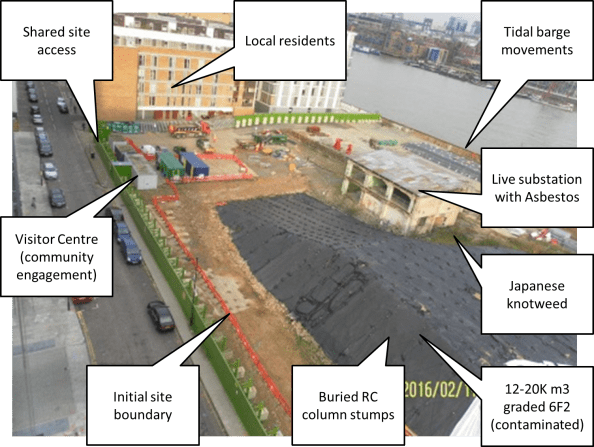
Figure 1. Site “Frictions”
Liaison with Neighbouring Works
This looks like it could be pretty messy. The initial CVB site boundary will roughly follow the line of the orange Chapter 8 fencing, CVB will control site access from the road and are responsible for security to the entire perimeter (including the parts within others PCs areas. As the stockpile is reduced we will expand our site (land/insurance permissions will take at least a week to be circulated before I can move a fence). Eventually we will get enough land mass to start work on the foundations for our office block (in the location where the green and blue containers are).
Local Residents
There are a number of restrictions on site activities owing to the clauses within the DCO. Noise planning and emissions will be closely monitored for all site activities. Residents have a 24hr hotline number to call if they have any issues with noise. We also have to maintain a visitor centre on site which we man on Wednesday evenings, and hold fortnightly Community Liaison Working Group (CLWG) meetings. The surrounding area is 50% expensive river front properties owned by influential characters (rumoured to include Captain Jean Luc Picard), and 50% social housing with a number of residents that are shift workers or unemployed and therefore in the property during working hours.
Stockpile Removal
Another contractor is responsible for removing the 6F2 stockpile from the earlier (2009) demolition works. Initially they had planned to load a 1000T barge each day, then changed this to two 500T barges. In the test run they managed to load most of a 500T barge within the tidal window before a hydraulic line burst. Consequently the estimate has been revised to one 500T barge per day. The works were further slowed by the discovery of suspected asbestos. Works to remove the stockpile have been halted since last Thursday whilst we await confirmation. Perhaps a coincidence but the asbestos was found by the contractor appointed to remove the spoil, and it could significantly increase their fee if the waste was reclassified as containing asbestos.
Concrete column stumps
The contractor also discovered that the stockpile is hiding a number of concrete column stumps (approx. 600mm sq). The removal of these is currently within ‘a scope gap’ between the different PCs, however if it falls to CVB to remove they will have to try and do it ‘quietly’, due to the restrictions of the DCO by progressively drilling and injecting an expanding composite to break down the concrete in layers.
Japanese Knotweed
An area of Japanese knotweed was discovered previously and has been receiving regular treatments, although it cannot be completely eradicated. This will eventually need t be removed to facilitate our new site access prior to the office foundations being constructed.
All of the above are fairly standard site issues within London, but nevertheless should generate some valuable learning over the next few weeks, and as I commented on Jo’s post, a lot of potential for neighbouring contracts to impact on our works. I should add that we receive a brief on the Contract Execution Plan on Friday so I hope to explore how we might deal with any delays caused to our project as a result of delayed enabling works under a separate contract.
Chambers Wharf
I wanted to do a blog about the issues that we’ve discovered on site, but then I realised that I haven’t actually written a blog to orientate people to the site. Therefore I’ll do two smaller blogs. I’m not planning on orientating people to the tunnel in general, unless people have specific questions, as it’s covered on the internet here http://www.tideway.london/the-tunnel/construction-sites/.
This blog will briefly introduce the site, and the following one will look at some of the issues in detail. This has the added benefit of not boring everyone too much, and boosting my blog numbers so that I can compete with Holtham and Nelson for the ‘Most Prolific Blogger Prize’.
I am attached to CVB JV (Costain, Vinci G.P. and Bachy Soletanche) who are delivering the Eastern section of the Thames Tideway Tunnel (TTT). I will be based on the main drive site located at Chambers Wharf and my first task is to coordinate the initial site works, to establish site and the temporary (until 2023) office and welfare facilities. The initial works will include utility diversions, demolition of structures including an existing substation, installation of welfare facilities (to be delivered by barge), installation of the cofferdam and demolition of the existing RC jetty. Once these works are underway we’ll have time to focus on the shaft excavation for the TBM.
Within the site boundary there are 2 other Principal Contractors currently working. One to clear the site following demolition works conducted in 2009, and the other to divert existing services and to install services for the Tunnel Boring Machine (TBM).
The phasing and integration of the different work packages works well on paper (figures 1 and 2 show how it is meant to work), but having attended two integration meetings it is clear that the programme appears to be moving towards one long critical path. The other PCs packages have been delayed by asbestos, noise and vibration complaints, and barge issues, and is starting to impact on the phasing of our works. I will expand on these site issues in my next blog. In the meantime, if our works are delayed due to other PCs failings I expect there will be some interesting contractual issues, but I will have to wait until the Contract Execution Plan is released before I can comment on this in more detail.
As the plan stands we will be establishing our own site on 21 Mar 16. Further than this, our progress is dependant entirely on the neighbouring contractors spoil removal, but with a good wind we will soon be starting works to the hoarding which is a not insignificant 3.6 – 5m structure supported by kentledge or posts, and excavating for the foundations for the modular office building.
The office modules are due to start arriving by barge on 21 Apr 16 and will be offloaded by a 100T crane, and then lifted in to place by a 200T crane. Simples!
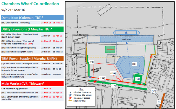
Figure 1. Site Integration w/c 21 Mar 16
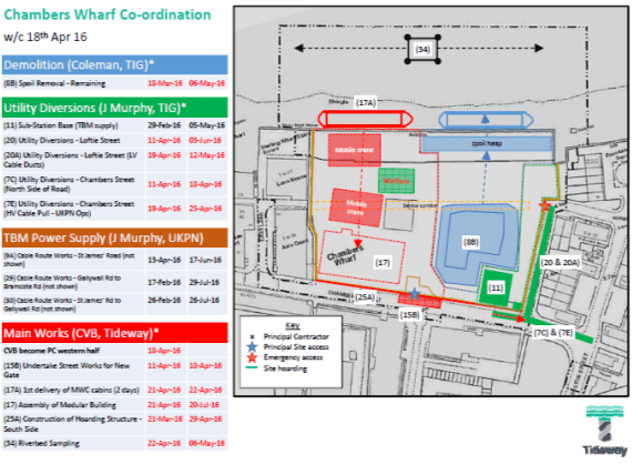
Figure 2. Site Integration w/c 18 Apr 16
