Archive
Trouble in paradise/Slough
The UK construction industry experienced the biggest contractor collapse since Carillion, when ISG Ltd entered administration in September (LINK). ISG, the UKs 6th biggest building firm, were the Principal Contractor on Yondr’s data centre campus, working on 9-figure design-and-build contracts on 2 of the 3 buildings. ISG bosses blamed loss-making contracts adopted prior to COVID-19. Overnight, 2200 jobs were lost and a multitude of military, prison, school and more government projects were thrown into chaos. As well as the brutal impact to ISG staff, there is of course the crippling knock-on effect to the supply chain, in which their sub-contractors across the portfolio may be forced to foot the bill for as-yet unpaid works.
In the immediate aftermath on our site, all works ceased and site was closed. Any access to the site office was on strict permit, and access to the dormant construction area required a specific RAMS. Yondr, a data centre developer acting as the CDM client, decided to self-deliver the remainder of the project. Administrators had begun taking control of ISG’s sites and so Yondr had to act rapidly, establishing a separate legal entity to act as the principal contractor – enter Yondr PC.
Back to square one
The following actions were then taken to begin re-mobilisation.
F10: A new F10 had to be opened with HSE and the site ownership formally changed to Yondr PC.
Novation: The now-defunct D&B contract meant the sub-contractors could essentially be novated, in their current structure, across to Yondr PC. This was of course far more complex than it sounds, with different works packages at different levels of completion, therefore different appetites for which (and how much) of ISG’s bills should be picked up. Also key to this – instilling confidence in the supply chain to continue procurement/production so that delays aren’t compounded.
Retention: There was a lot of experience, knowledge and talent in the ISG project management team. Yondr moved quickly to hire critical staff (under Yondr PC) previously involved with the project to keep the ball rolling, rather than a lengthy recruitment and project-familiarisation process.
Inductions: Safe systems of work, H&S and all manner of Principal Contractor responsibilities became Yondr PCs remit. A lot of paperwork behind the scenes and notably, re-inducting every one of the 100’s of employees on site.
Licenses: Re-establishing software licenses may seem a minor point, though it was extremely impactful. Data exchange platforms (e.g. for drawing submittals), site access scanners, project tracking software and much more were all managed under an ISG license and could not be ‘novated’. Salvaging documents and details with mass-downloads ensued prior to the old licenses being revoked, though this is likely to cause version control issues down the line.
Managerial processes: Establishing managerial processes with the novated sub-contractors was important – this essentially provided a clean slate for how business is to be conducted. This included meeting beat-rates, submission procedures, RFI process flows and many more.
Re-baselining: The stand-down period caused a significant delay, and post-re-mobilisation required some getting back up to speed, such as re-assembling workforces that had been sent home and maintaining/re-calibrating kit that had been left dormant on site for weeks. Once site was back up and running, an all-hands workshop was held to re-baseline the programme and confirm a new timeline.
2 months later
There may well be unforeseen issues that arise, with site not long re-opened. However, the early mood music is positive. Re-mobilising had the potential to be complete chaos; Yondr acted decisively and with a clear plan to control that chaos. The project moves forward and any delays have been well-absorbed within individual packages. The key lesson from this experience: ‘war-gaming’ in construction is a necessity. The company had an idea of what could go wrong and ideas to mitigate ahead of time, despite no forewarning of the collapse. That ensured this project was pulled back from the brink of disaster.
Reinforced Timber in Construction
Having written a TMR on Low Carbon Concrete and the difficulties of specifying it on site, I was invited to attend a MECLA (Materials and Embodied Carbon Leaders’ Alliance) event at the University of New South Wales (UNSW). MECLA are an Australian Government think-tank, combining industry, academic and government professionals, and as part of the conference were reviewing the latest research at the University. Part of this, that I thought would be interesting to the wider course, was research into reinforced timber using prefabricated composite elements by Prof Hamid Valipour. The intent is that these can be used as structural members in mid-rise structures (4-5 storeys).
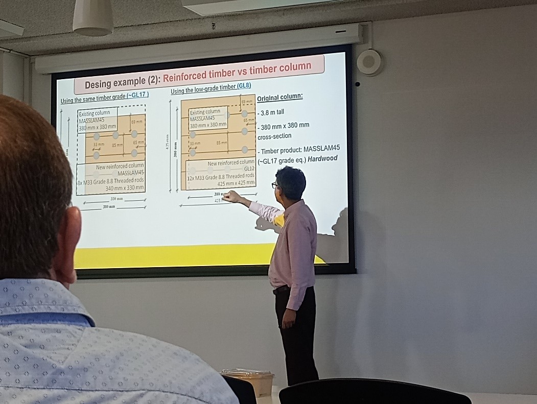
One benefit of the research was that a timber member could be replaced with the same quality timber containing steel reinforcing, leading to a significant reduction in required cross-section to resist load. However, the main sustainability benefit was that high quality timber could be replaced with low-grade timber, such as Douglas Fir. When reinforced with steel rebar, this low-grade timber would still have a smaller cross-section than significantly higher quality timber used on its own and allow lower quality, faster growing timber to be used for structural purposes.
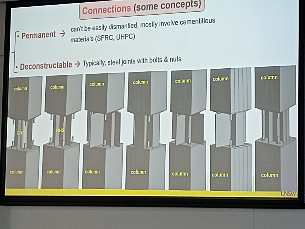
Connections could be de-constructable, created using steel plates (as shown above). These are bolted onto the end of the threaded rebar (the same bars as used in concrete) that protruded from the timber members, allowing the joints and structure to be dismantled at the end of its life. Alternatively, for more permanent structures ultra-high strength concrete, that cured within 48hrs to over 100MPa, was used to connect members, allowing the structure to be load bearing and built in a short period of time, as well as protecting joints from fire.
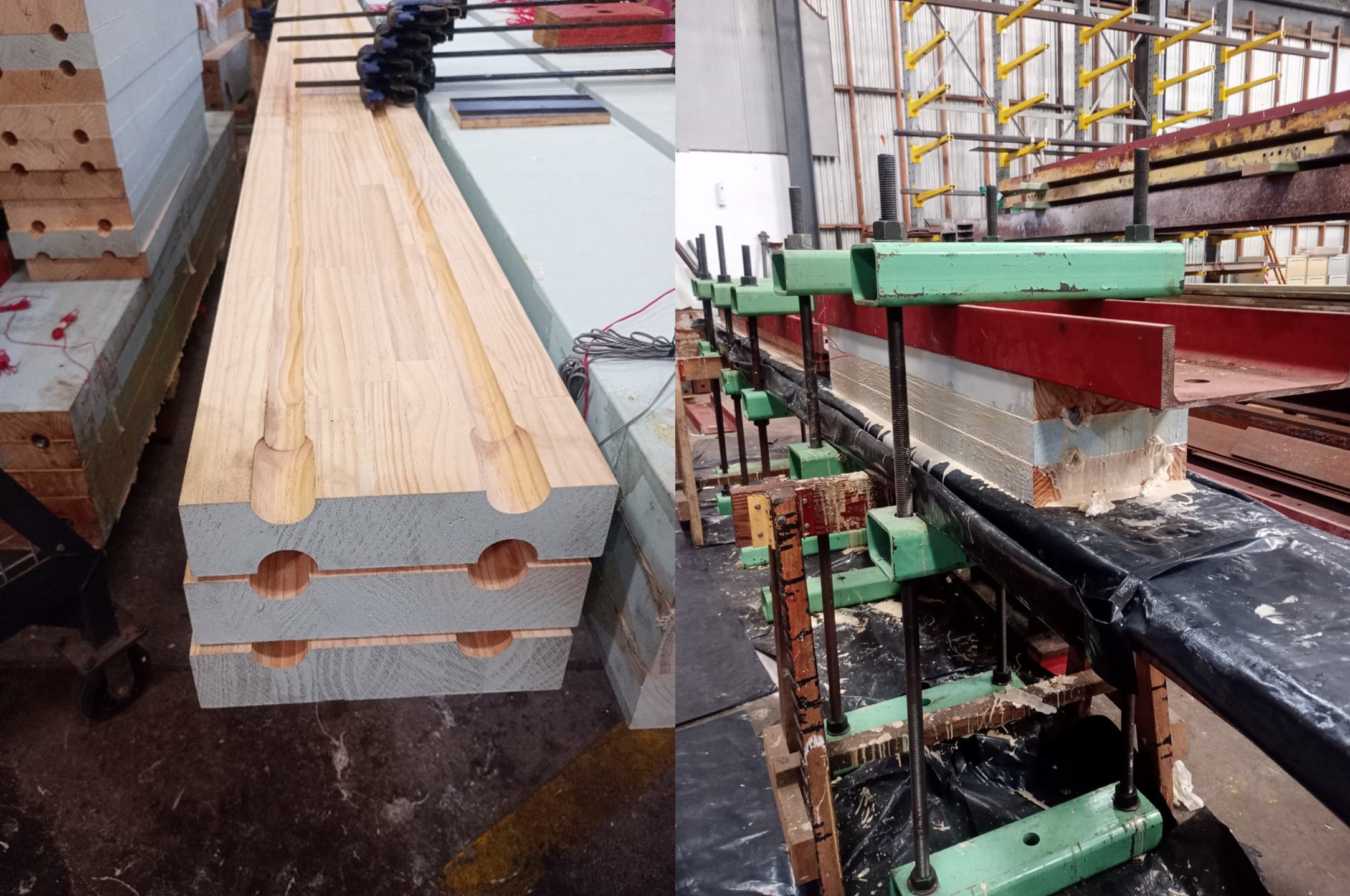
The members themselves are created form beams of glue-laminated timber with grooves cut into them using a router table. The steel reinforcement bar is then placed inside and a glue is poured into the joints to bond the bars and timbers together. These are then clamped and held in compression for 48hrs. Not only are the members very strong, but due to the steel being encased inside the timber, they also have a high resistance to fire.
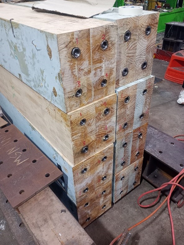
The rebar can either be threaded to be a male or female end as required. They can then be rapidly assembled on site.
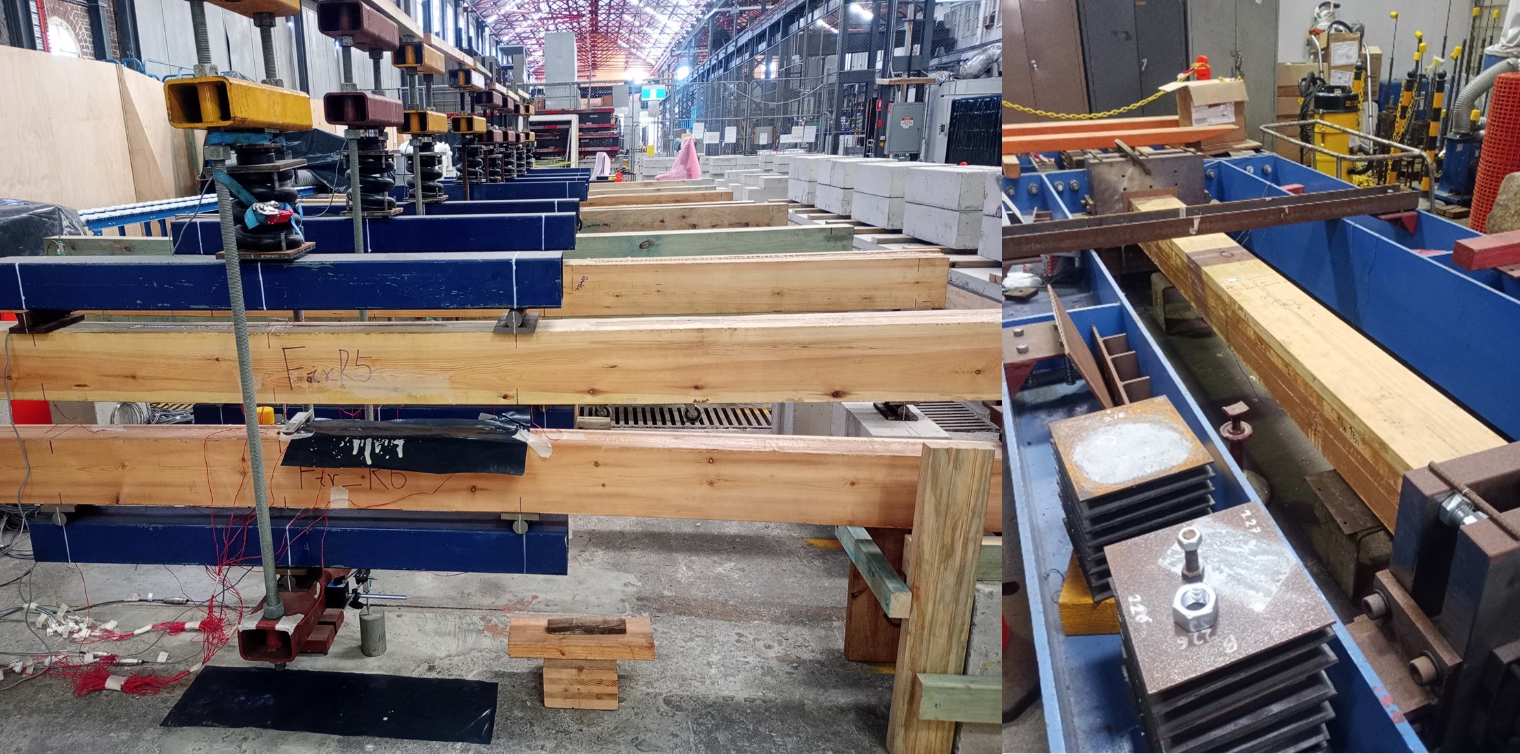
Using this method, beams and columns have been tested with some being left for up to two years to measure creep and verify the quality of the bonds. Beams were also tested for vibration and deflection. It was found that once beam spans were limited to 8.5-9m before vibration and deflection became the constraining factors.
The beams have also been tested as a composite in conjunction with concrete slabs to produce floors. One key consideration when used in this manner was that a membrane needed to be placed between the concrete and timber when the concrete was poured. This was because the concrete would chemically attack the timber, reducing strength by around 1/3.
So far, the project has been a resounding success and Prof Valipour is trying to ensure that all of these members meet existing timber codes to allow a rapid transition into use. However, he did state that it will come down to design consultants to hold the risk of utilising them in design and identifying whether they can meet required design lives (the irony was not lost on me). This further demonstrates the difficulty of utilising new research and techniques in industry but may be something we are able to work with in the near future.
Are your briefings understood?
We had an incident on site last week where a 9 tonne dumper rolled over. The driver was OK, he escaped with a broken wrist and collar bone. The initial, unofficial, assessment is that this was a simple case of driver error as it appears that he reversed off of the haul road. However, as often seems to be the case in situations like this, there is always more than meets the eye. It turns out that the supervisor has only just joined the job and was authorised as a ‘competent person’ by the project director just 6 days before the incident. The usual foreman was off on holiday and was not providing the same amount of supervision as is normally applied in the area. (I should stress that this is routine business; if a foreman or supervisor is away on holiday, their workload is often shared between others of the same grade.) Finally, had the dumper driver understood the daily briefing?
Our labour (ground workers, excavator operators, multi-skilled operators etc) tend not to have English as their first language. Of the 19 gangs we have on site, only 3 have a supervisor where English is their first language. Adding to this complexity is the fact that the gangs are not made up of people who speak a common language, the language used on site to communicate is English. But how much does the Romanian ground worker understand the brief given by his Indian supervisor? What about the Pakistani dumper driver receiving instructions over the radio from his Albanian supervisor? Not only are we communicating in a language foreign to everyone, the language that is being used to communicate between them is being delivered by someone else who does not always have a good grasp of English.
This begs 2 questions; firstly, where is the British workforce? A ground worker earns £22/hour and many of them work 11 hours a day for 6 days a week. You do the maths, but this is a lucrative job for an unskilled labourer. The foreman are mainly from a British background, but that won’t be true for much longer if there is no one coming through.
Secondly, and more importantly, should we be adjusting our method of communication to ensure that everyone understands daily briefings? Should we be asking our supervisors to use a translating software so that the brief is input accurately by whoever is giving it and clearly understood by the one receiving it? Surely our responsibility is to ensure that everyone works safely and if we have to make allowances by changing our communication style, then we should be doing it!
Does anyone else have similar challenges? Has anyone already overcome this problem and is already doing briefings using a translating software?
Surrey based CPD – a tour of the M25/A3 Junction 10, Heathrow Airport and Data Warehouses
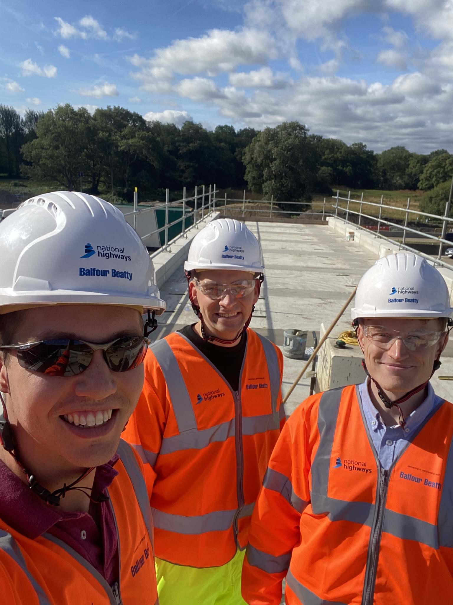
On Thursday 15th August, Capt Rich Swarbrick, Capt Joe Nield and I (Capt Joe Solway) managed to finally co-ordinate ourselves and spent the day taking turns to host each other on our respective sites. We started our journey in the M25/A3 Junction 10 traffic, before Rich gave us a flying tour airside of Heathrow and Joe took the after lunch shift in the data warehouses.
We started the day at Nutberry compound, the base location for the M25/A3 Junction 10 upgrade project where I showed Joe and Rich a 5 minute video put together by National Highways outlining the scheme. If you want to give the video a watch yourself, you can find it here: https://nationalhighways.co.uk/our-roads/south-east/m25-junction-10/#panel-id-41261b7e-591a-4f9d-bbd6-5ae9a9043c9f.
After the video we headed out to site to see a bridge that is being constructed alongside the M25 in a place called Buxton woods. The bridge is a composite bridge with 2 steel beams approximately 3m deep with a concrete deck. They deck had just finished being poured and we were able to climb up onto it to have a look further. I was responsible for constructing the working platform which was quite problematic (future blog post will provide further details) and also for constructing all of the platforms that will be used to move the bridge into place.
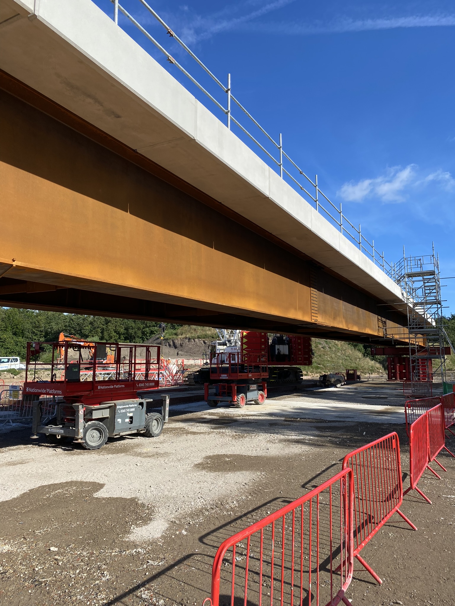
The bridge is being moved into location via a self-propelled modular transporter (SPMT) on a full road closure (currently booked for October for those in the local area!) where it will be driven out across the M25 and moved into position at Clearmount, about 100m away. Frustratingly, one of the platforms that was constructed for this has been dug up by the drainage sub-contractor, with new drainage laid right underneath where the bridge will be travelling. This is going to pose some challenges in the future, but hopefully nothing that will slow the project down even further! We discussed the challenges associated with sub-contractors and their own programmes and how sometimes construction appears to take place out of sequence and causes more problems than it solves!
At Heathrow Airport, we visited the various airside projects which Rich is involved in and discussed the unique challenges and risks associated with them.
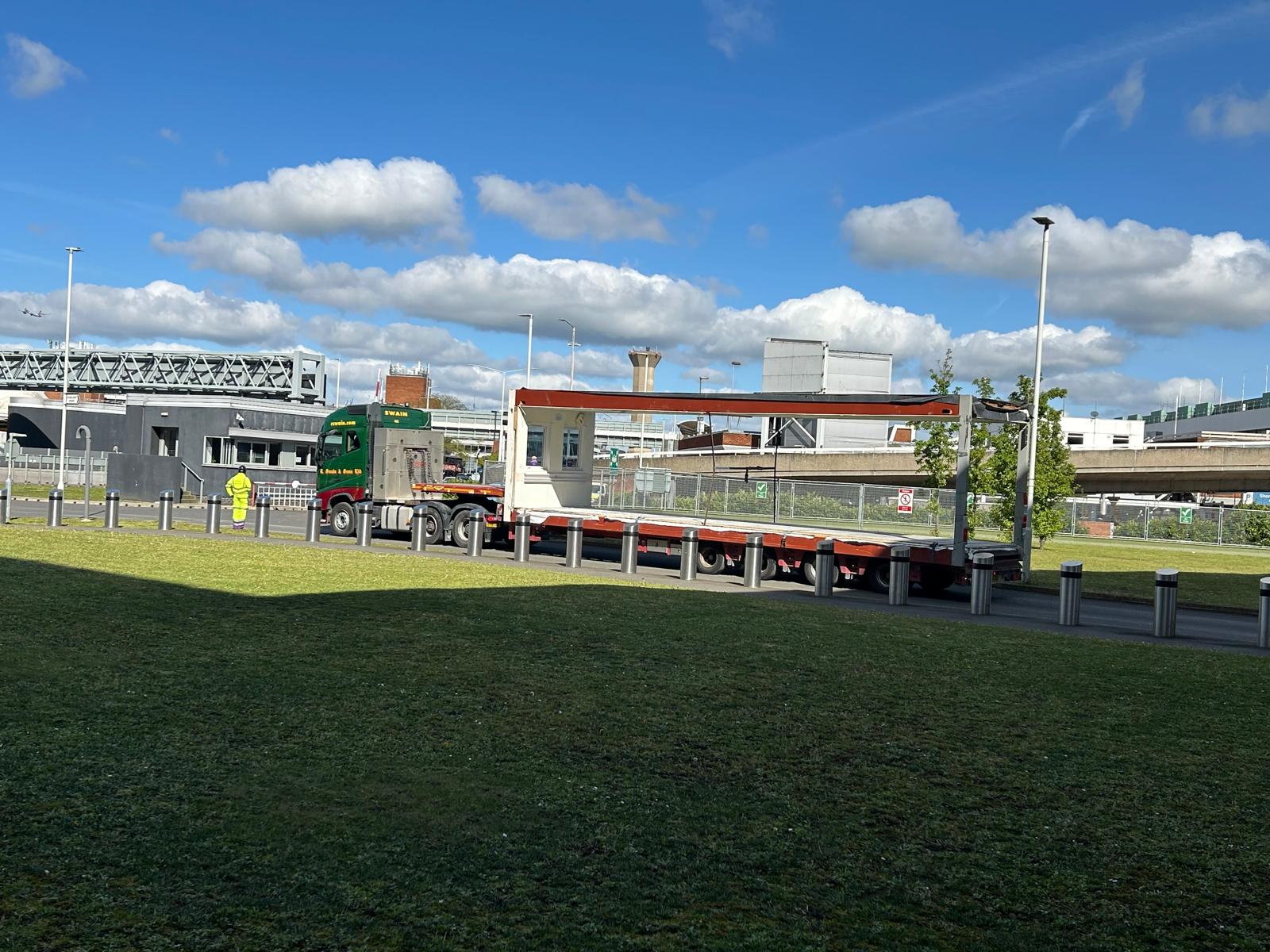
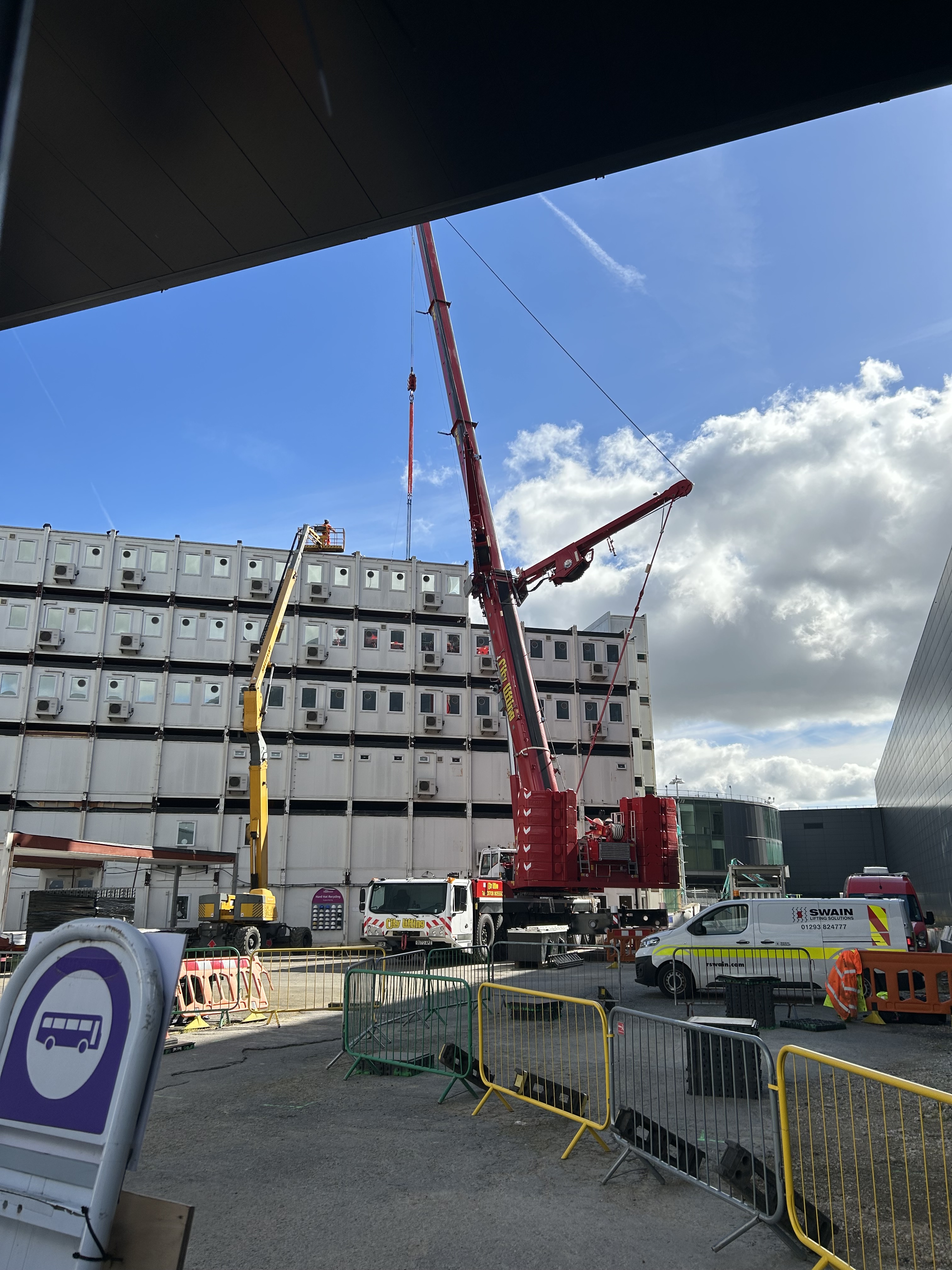
At Starlight Point, the topic of his TMR 1, the final crane lift had been successfully carried out earlier in the week. We discussed the logistical burden surrounding the dismantling and transport of large modular units through a congested Central Terminal Area, and how the risk of Foreign Object Debris has been mitigated.
We then discussed the challenges surrounding Reinforced Autoclaved Aerated Concrete (RAAC) at the airport, including how it is being managed, the research which is ongoing to better understand it’s properties as it reaches the end of design life, and how the risk is being managed with support from specialists within the engineering industry.
Next we looked at the moth-balled Terminal 1, due for full demolition over the next decade. Within the building are a multitude of services such as HV cables, security and data feeds which are still active and must be fully identified, and subsequently diverted or protected during any works.
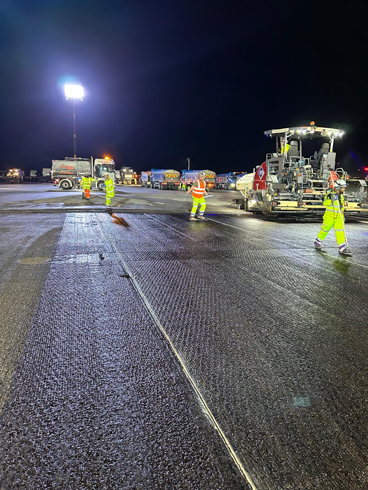
Finally, we visited the asphalt batching plants being used for the Southern Runway Rehabilitation project. We discussed the works which are being carried out overnight to plane and re-lay the top two layers of the runway, all within a short overnight working window, at massive risk to the airfield operation.
At the Yondr data centre campus, we visited a 3-storey 30MW building. That building alone utilises 26x 2400kW generators, 26x 904kW electrical plant rooms and 24x 1697kW chillers. The ongoing works included installation of chiller noise attenuation, low voltage cable pulling, cladding install and the relocation of site accommodation.
We discussed an ongoing challenge to route new underground services through a congested zone to supply the newest data centre, involving two different Principal Designers and Principal Contractors. A scope gap in the contracts meant there was a 30 metre (approx.) stretch that was undesigned by either team. This has been an important interface between civils and M&E specialists, trying to adhere to underground service code/regulations whilst carrying out considerable ground works.
We then looked at the considerable redundancy across a data centre, from diverse power streams (utility and generators) to chiller resilience (4n3 system, where 4 chillers cover each 3-chiller duty). This was most evident in the ‘technical corridor’ where many of the building services diverge. We ended with an introduction to hot-aisle containment, a common environmental control strategy within data centres. Fan wall units interact with the chilled water system to draw heat from the server racks, maintaining server integrity.
Value Engineering vs Joe
With three data centres on one campus, and residential properties approximately 50m away, the acoustic limits on site are very tight. With over 70x 2.4MW generators and 1.6MW chillers (amongst far more plant), the noise output is significant. We’re pretty much one shout away from our planning permission limits.
Load banks (LB) are required within data centres to test the generators on-load twice annually. Typically, the LB will be fixed in place and have busbar run to each generator, testing via the flick of a switch. Value engineering, in all it’s glory, led to the removal of a fixed LB for a far cheaper mobile unit, sat on a trailer and driven to each of the generators. The CAPEX savings are in the millions (though the OPEX is questionable). The issue with mobile LBs on this site is that the units can’t be routinely attenuated for noise, due to the centre of weight on the trailer and ventilation requirements.
The pertinent info for the mobile LB (not yet procured) is:
- 88dbA noise emissions, likely upwards.
- At least 2m space required to the sides to allow air intake.
- No cover above to allow exhaust of air (fire risk).
- Broadly 3.5x2x2.5m dimensions (HxWxL, on trailer).
From multiple vendors and data sheets, we will significantly breach noise limits. Some work with the acoustics team has shown that we need to reduce the dBA to 82@1m and 56@10m to the side. Modelling shows for the closest test location to the nearest noise receptor (residential), an acoustic screen would need to be over 7m tall, 2m away to the side, to screen the upwards trajectory of the noise emissions. This would then have to be wheeled around with the generator, stored, windproofed, etc… Highly unpractical.
I have also looked at:
- Procuring a compliant load bank. Tests show the load bank would need to emit 72dBA – a huge acoustical gap on a logarithmic scale.
- Buying the nearest receptor. Unsavoury and questions remain about breaching noise limits at other receptors.
- Screening the large fence line in front of the receptor – deemed ineffective, due to soundwave trajectory.
My preference and recommendation is to retrofit the fixed load bank and attenuate in place. A business case is being made elsewhere, but there may be no way back. So, keen to hear if anyone has any mobile acoustic solutions/suggestions to this kind of problem?
Glued Insulated Joints and Why Not to Use Metal Measuring Tapes
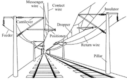
One for the E&Ms but explained in Civil speak! Many Australian trains are electric, particularly in urban areas. These are powered by overhead cables and a pantograph system. Electricity is provided to the train as 1500V, DC power and is converted through a rectifier and inverter to three-phase AC power to power the motors. The circuit is completed through the train wheels touching the steel rails which act as a return conductor to the nearest transformer.
Additionally, there is a second current in the tracks, at a different frequency and very low voltage, that is used for signaling. The wheels and axles of a train entering a track circuit connect and short circuit the two running rails together, causing the current to drop to zero. This provides information to the signal gantries, turning the lights red to tell other drivers that there is a train on the section of track ahead of them. This information is also fed to the control desk to allow the tracking of all trains in the network. The system is designed to make signals turn red everywhere if there is a power outage, but the voltage is so low that water pooling between the rails does not cause it to short.
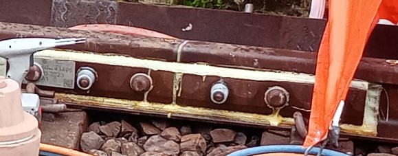
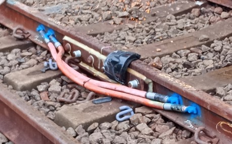
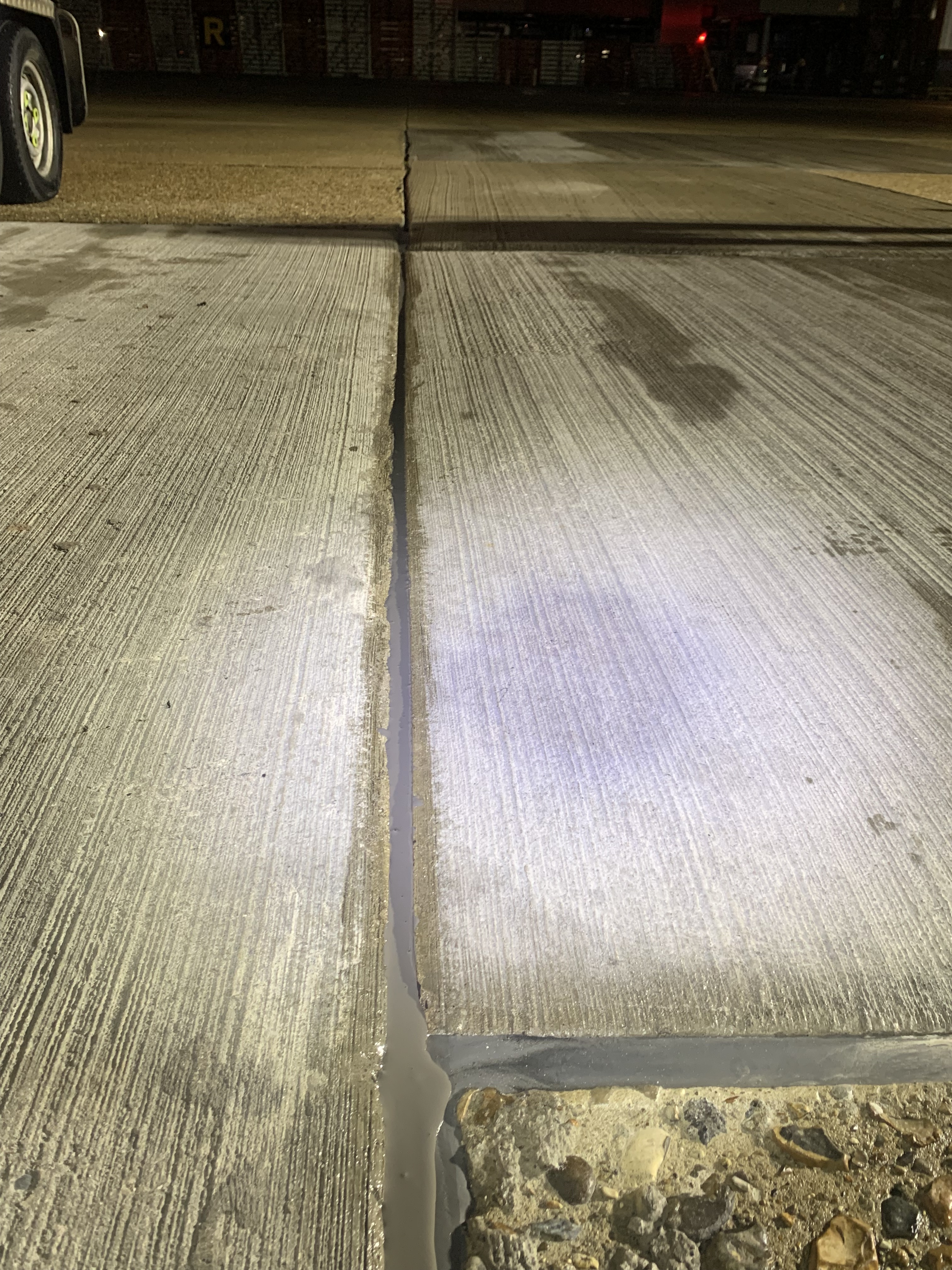
For these track circuits to work, sections of rail need to be broken up with insulated joints to allow more accurate location data to be provided. These are known as Glued Insulated Joints (GIJs), as shown in the picture below) and come prefabricated into a section of rail 3.43m or 4.57m long (or specially made if required). These are tested under factory conditions to ensure they function correctly. To fit them, a section of the existing rail has to be cut out and the new prefabricated section is welded into place. This falls to the civils team.
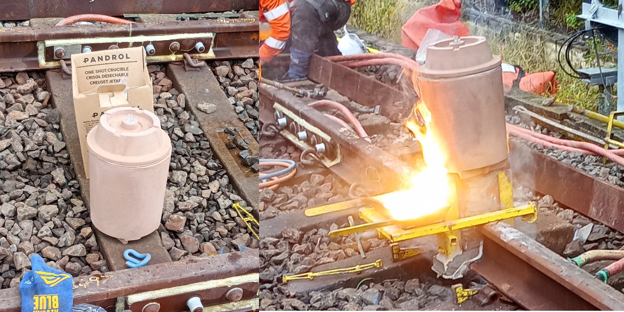
A single use mold is fitted over the gap in the rails and rubbed in place to shape it as closely as possible to their worn shape. It is then sealed with a clay mix and an oxyacetylene torch is used as a preheating flame to warm the rails that will be joined (to 1000 degrees) and to fire the clay.
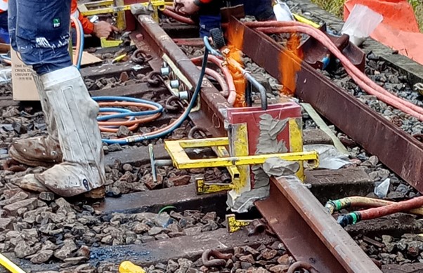
A single use crucible is then placed on top and ignited by sparking between the two prongs of an igniter fuse. The crucible’s filling consists of 37% aluminium, 13% steel, 37 % iron oxide and 13% alloying. This mixture is known as thermit and when ignited a reaction takes place that raises the temperature of the contents to 2500oC within 30 seconds. This reaction creates liquid steel which sinks to the bottom of the mold and liquid slag that rises and overflows into the slag tray.
This is then allowed to partially cool before a hydraulic trimmer is used to shear off excess material and break away the mould.
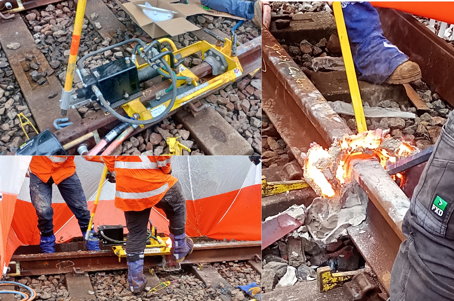
A rough grinding is then carried out using a spinning grinding stone that can be raised and lowered. The joint is then allowed to cool to ambient temperature and shrink completely before a finishing grind is carried out. This prevents a dip forming that would mean the joint has to be cut out and replaced (as the acceptable vertical tolerance across the joint is only 0.3-0.4mm across the two rails). This is checked using a straight edge.
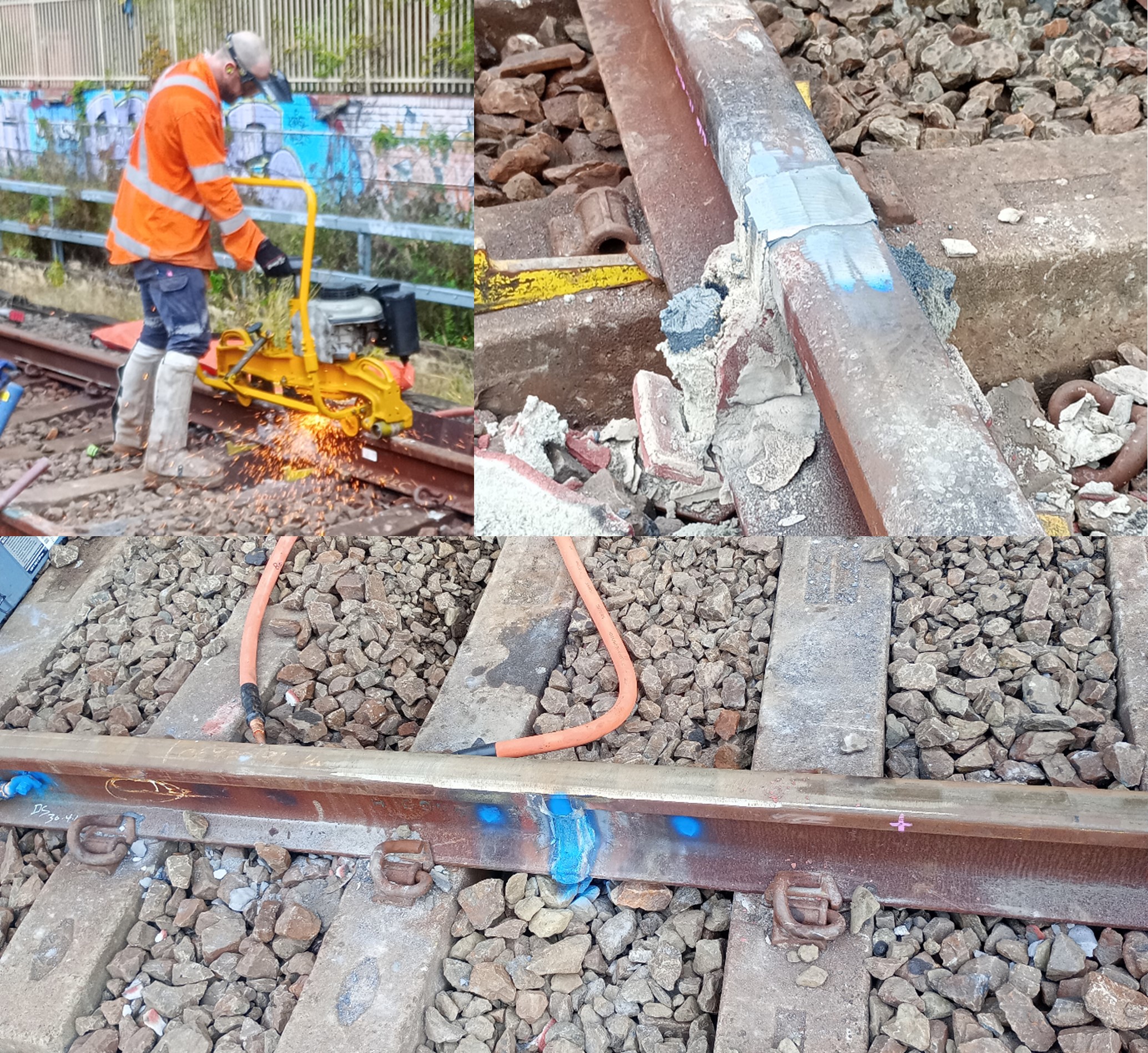
Cables are then welded either side of the GIJ. These are left bonded when it is not in use and will be removed once the signals have been commissioned.
Key takeaway
Rails may be live even if it the power lines are overhead and have been disconnected – no metal measuring tapes in the rail corridor!
More Trains More Services – Next Rail
For my Phase 2 placement, I am working as a Project Engineer for John Holland supporting the development of rail infrastructure in Sydney. This is as part of the More Trains More Services (MTMS) multi-billion-dollar programme and is focused on power upgrades, signalling, stabling facilities and station platform upgrades. This will deliver trains every two and a half minutes in peak hours on key corridors.
Key Project Stakeholders
John Holland Group (the Principal Contractor) is working in partnership with Transport for New South Wales (the Client) and Jacobs Engineering Group (the Principal Designer). The three groups have been combined as “Next Rail” and are described as an Incentivised Delivery Entity (IDE), with the intent of sharing any benefits/losses on completion of the programme. Additionally, Sydney Trains (a department of TfNSW) is the Operator/Maintainer and take a keen interest in works that are done. This partnership has created a complicated hierarchy and has already led to stakeholder engagement and expectation management being a key part of my role.
The Delivery Commissioning and Handover Team.
My initial work has largely consisted of closing snags and overseeing commissioning work. For example:
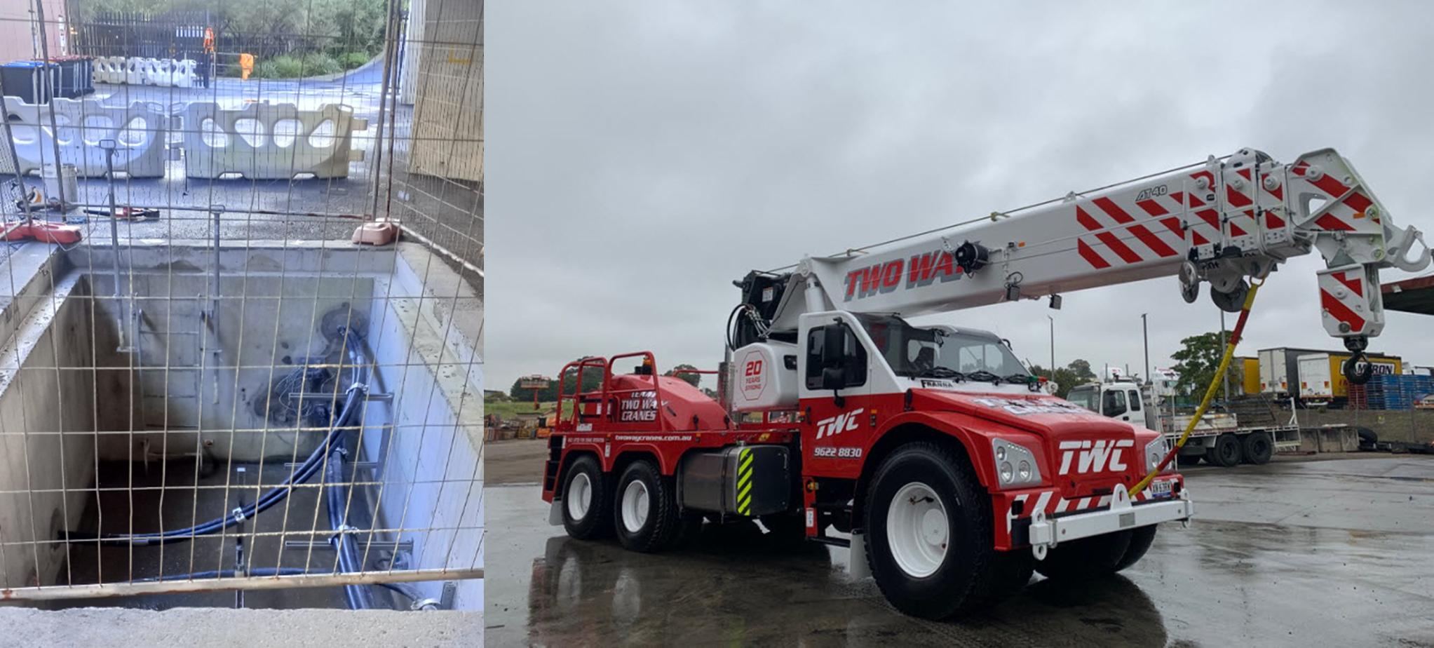
- Overseeing the commissioning of 11kV feeder cables from a new substation (to increase supply) and removing redundant ones. This was done during the early morning when electric trains were not running. It required use of a Franna crane to lift a cable pit cover (after the cables had been isolated) due to the overhead restrictions. This was a piece of equipment I had not seen before and was able to lift the 5.5ton lid with the boom in the lowered position (shown below).
- Replacement of sections of overhead wiring and strengthening overhead gantries to resist torsion. This was heavily delayed due to power leakage between lines – it is often difficult to isolate lines to below the 50V required for work to be allowed to take place. This causes significant delays and immense cost to Next Rail despite being out of their control. Other issues have been the need to vermin proof signalling boxes to prevent chewed cables!

Wolli Creek Demolition Task
The main task I am working towards is the demolition of some redundant assets and their replacement with an access road/long vehicle turning area. This will include importing fill from another site to raise the existing ground level and there is current discussion as to whether this can be ‘contaminated material’. The site is situated at a rail junction, between two rail corridors and an area of residential high-rise flats.
Key risks noted so far have been:
- Contaminated Ground. Rail corridors are often built on landfill and due to oil and waste leaks from locomotives, almost all the sites have been found to have contaminated ground during excavation (even asbestos panels encased in concrete). This has led to significant costs and delays that were not considered in the planning stages.
- Underground Services. As well as 1500V DC overhead cables, the site is surrounded by live underground services and a high-pressure gas main. In Australia, “positive identification” and “positive location” is required, meaning that any excavation is likely to require a suction excavator.
A Developer Secondment – Best of Both Worlds?
Three weeks into working for a Data Centre (DC) developer, it is clear that the experience won’t follow the typical ‘blueprint’ of a PET course secondment. The developer can identify opportunities for clients, initiate a project and create concept designs, before a Release for Proposal (RFP) for detailed design and then construction contractors. They are then responsible for overall project planning and management, scheduling, budgeting, risk management and quality. In the world of DCs, they are the specialist link between Contractor and Client.
The typical secondment of 7 months with the contractor followed by 7 months in the design office is tried and tested, providing the site experience necessary to lead engineering works and the technical knowledge to oversee technical designs. The developer space, on the other hand, appears considerably more fluid. Depending on the relationship with the employer, there are links to the contractor, the designer, the commercial team, legal, H&S, QA and more throughout the project. Earlier exposure to the ‘bigger picture’ and the wider stakeholders can present an opportunity to pick and choose challenges to tailor the experience.
My experience will primarily be within the DC developer design team, with a focus on a construction in Slough. There are 3 different buildings on site at different RIBA stages (commissioning, construction and technical design). Placement within a developer team appears to present significant opportunities and challenges for gaining the required experience against UKSPEC standards, discussed below.
Opportunities:
- The developer has significant commercial involvement throughout, from routine client and contractor management to OFCI (Owner furnished, Contractor installed) equipment procurement.
- The developers are the specialists; the contractor may not be. This forces an intimate understanding of the design to facilitate construction, in order to meet the unique client requirements. Design, development and engineering problem solving (Comp B) opportunities are everywhere you look.
- RFI and change management – the developer will manage principle designers and contractors through the RFI and change process. This presents considerable opportunity to develop technical knowledge (Comp A) across the project life cycle.
- This ensures a unique, holistic project experience throughout, with design input through to quality assurance and commissioning responsibilities.
Challenges:
- There isn’t the same concentrated site experience that would be achieved with a contractor. Developer project management is done at a high level (particularly the oversight of principle contractor), meaning the opportunities to lead and manage works are fewer (Comp C).
- Working for a multi-disciplinary specialist = a steep learning curve! Understanding the interfaces between M&E, Civil & Structural, Utilities and OFCI vendors in an unknown-to-you industry is a tall task.
- It isn’t the ‘proven route’. The experience isn’t on rails; you have to work hard to understand where opportunities exist and where you can add value.
The result is a fluid role that could mould to the required experience for the student. Provided that opportunities are exploited to lead on site, whether verifying ongoing works or carrying out H&S reviews, the work in the developer space should marry up with the UKSPEC competencies. For the PET course, this could provide an alternative path towards chartership in expanding, innovational industries.
Heathrow Airport Civils Phase 2
I am around 4 weeks into Phase 2, working in the Civil Engineering team within Technical Services at Heathrow Airport. The team owns, on behalf of the business, all civil and structural engineering assets at Heathrow including the two runways, five terminals, 65 bridges, 48 tunnels, 66 retaining structures, 150+ buildings and 200+ km of roads. We are involved throughout the whole asset life cycle; we ensure that new structures meet the correct requirements and regulations, we plan and implement the maintenance regimes, and we are involved in the end-of-life management such as decommissioning and demolition.
As we are quite a small team I am not solely aligned to one project, instead team members work together on areas of expertise or where capacity allows. However the major project I have been given to be technical lead on is the T2 Baggage Programme (T2B), and specifically within this the various demolition projects which are ongoing and scheduled. T2B is part of a £3.6 billion capital investment plan: it is a major programme at Heathrow with five tranches, each with their own projects, with civil engineering involved at every stage. The programme seeks to expand the T2 baggage handling system, which currently operates in the moth-balled T1. It will also (eventually) see the full demolition of T1, to be replaced by a whole new terminal. The programme must be completed without impacting current terminal capacity (i.e. provision of stands) and/or the efficiency, safety and resilience of the airfield operation in the vicinity of T1/T2.
Challenges at Heathrow:
The majority of the airport was built in the 1960s-1980s and this has created a variety of issues. Many of the terminals contain significant amounts of asbestos and RAAC (and sometimes RAAC coated in asbestos for extra risk). The RAAC has reached the end of its design life and in some areas is in poor condition and is undergoing regular inspections and maintenance to extend its safe use as much as possible, particularly where is it load- or end-bearing.
In addition, BIM and H&S files were unheard of when much of the infrastructure was built, meaning there are some assets with no recorded information such as calculations, drawings or maintenance schedules. One example is Calshott bridge, built at some point in the 1950s, which spans the main tunnel route into the central terminals – quite a risk if something were to go wrong. We have been tasked to conduct a loading assessment, but the bridge has been covered in cladding and services meaning that maintenance or even a proper visual inspection is impossible, and without any supporting documentation it is a real challenge.
Heathrow is under strict regulation by the Civil Aviation Authority and receives hefty fines for any delays or quality issues which affect the airlines. The first consideration on any engineering project is the impact on the operational effectiveness of the airport, meaning often the chosen solution is a ‘quick fix’ to extend the asset life rather than a permanent solution which could be disruptive and therefore costly.
Below are some photos from my time so far:
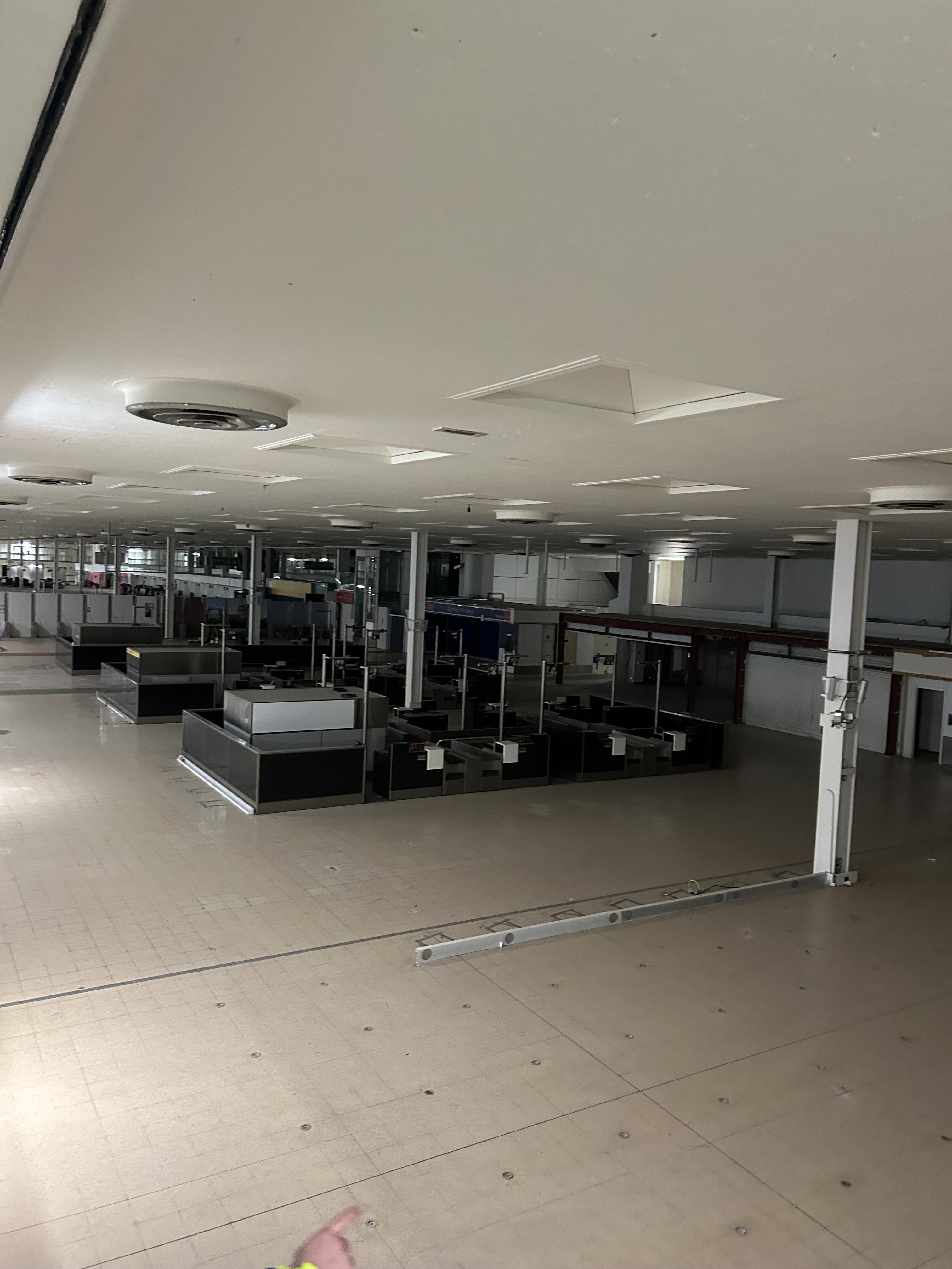
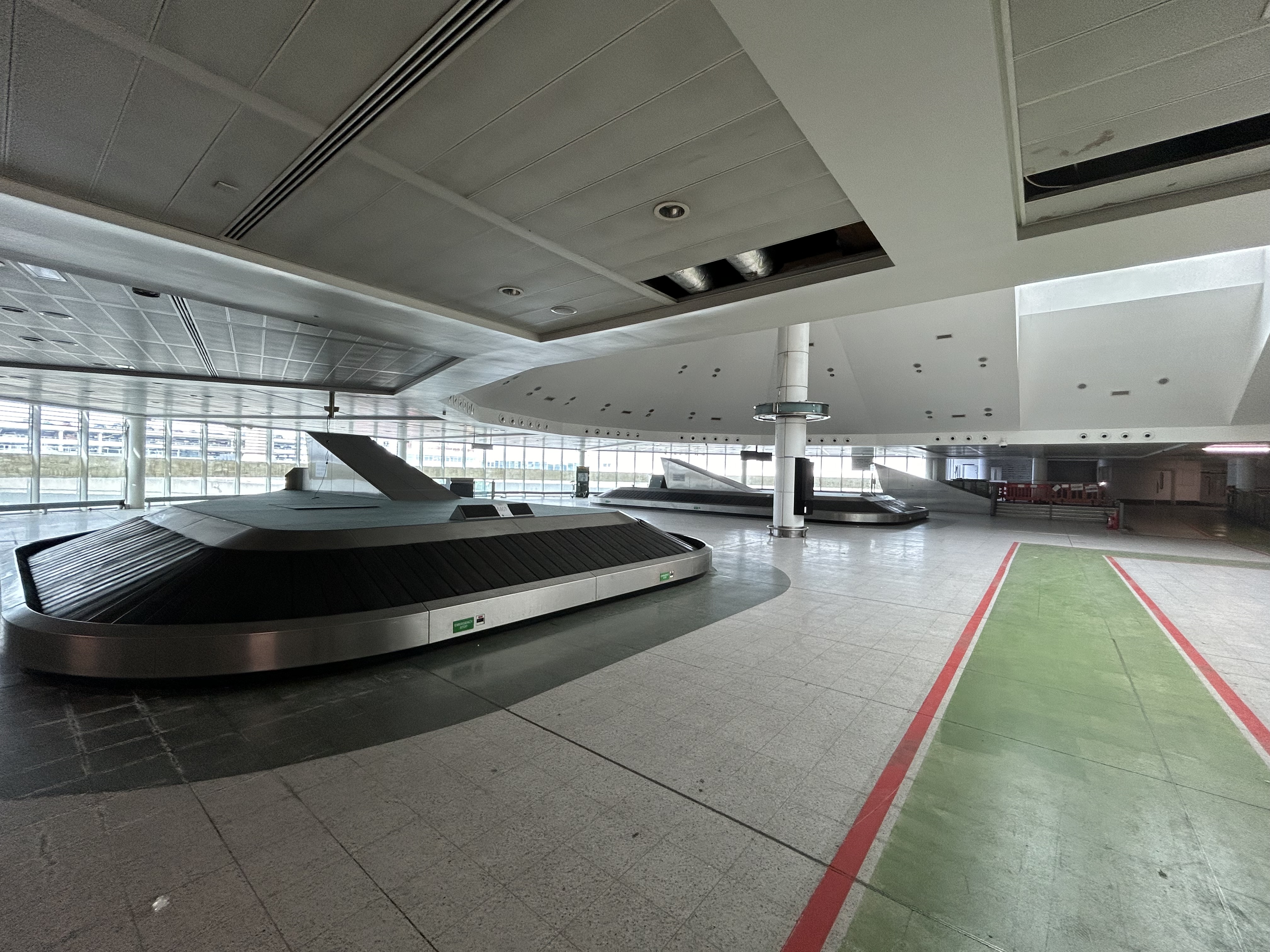
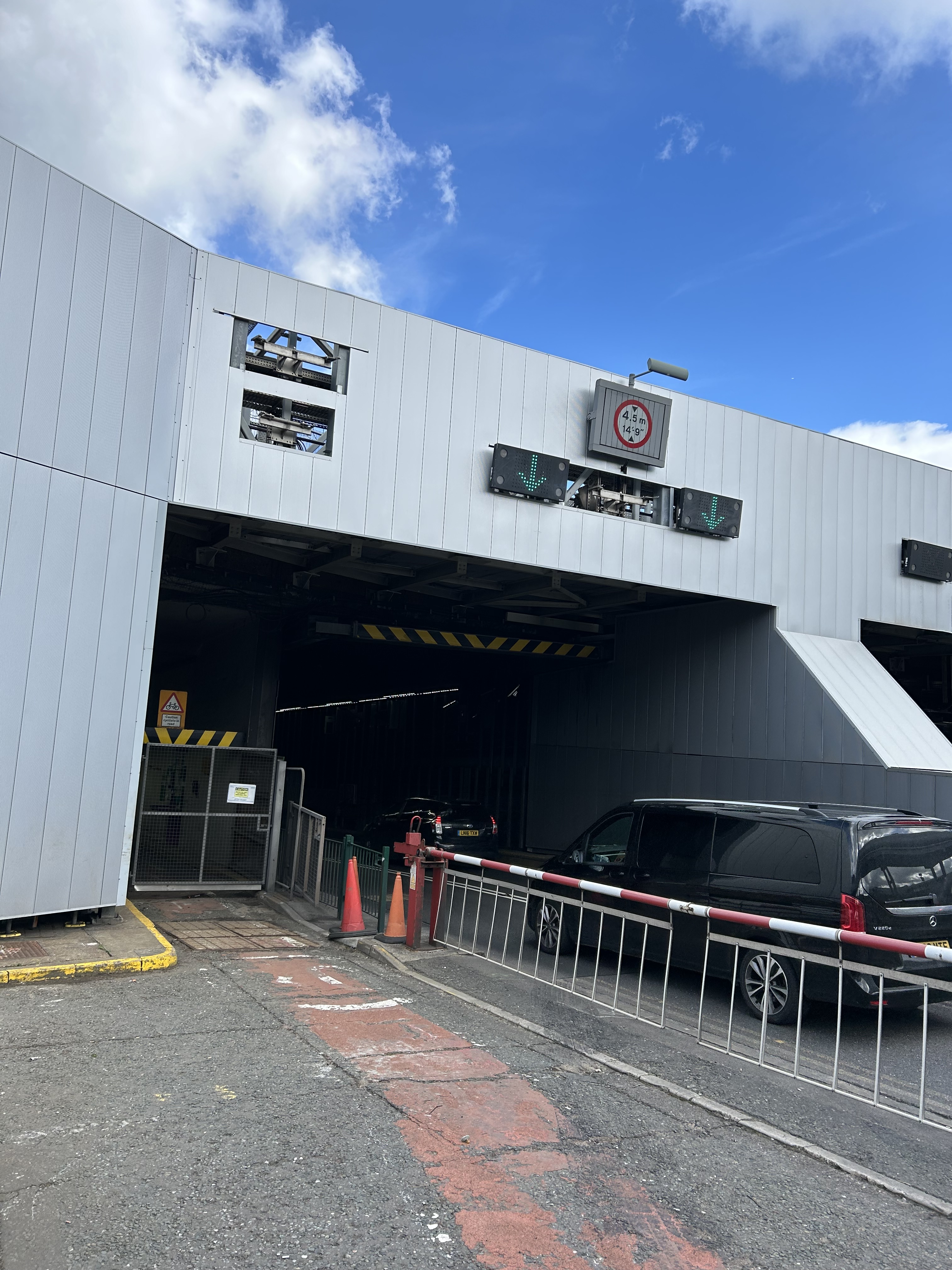
Inside the moth-balled Terminal 1. How do you safely demolish an entire terminal (full of asbestos) in the middle of the UK’s busiest airport?
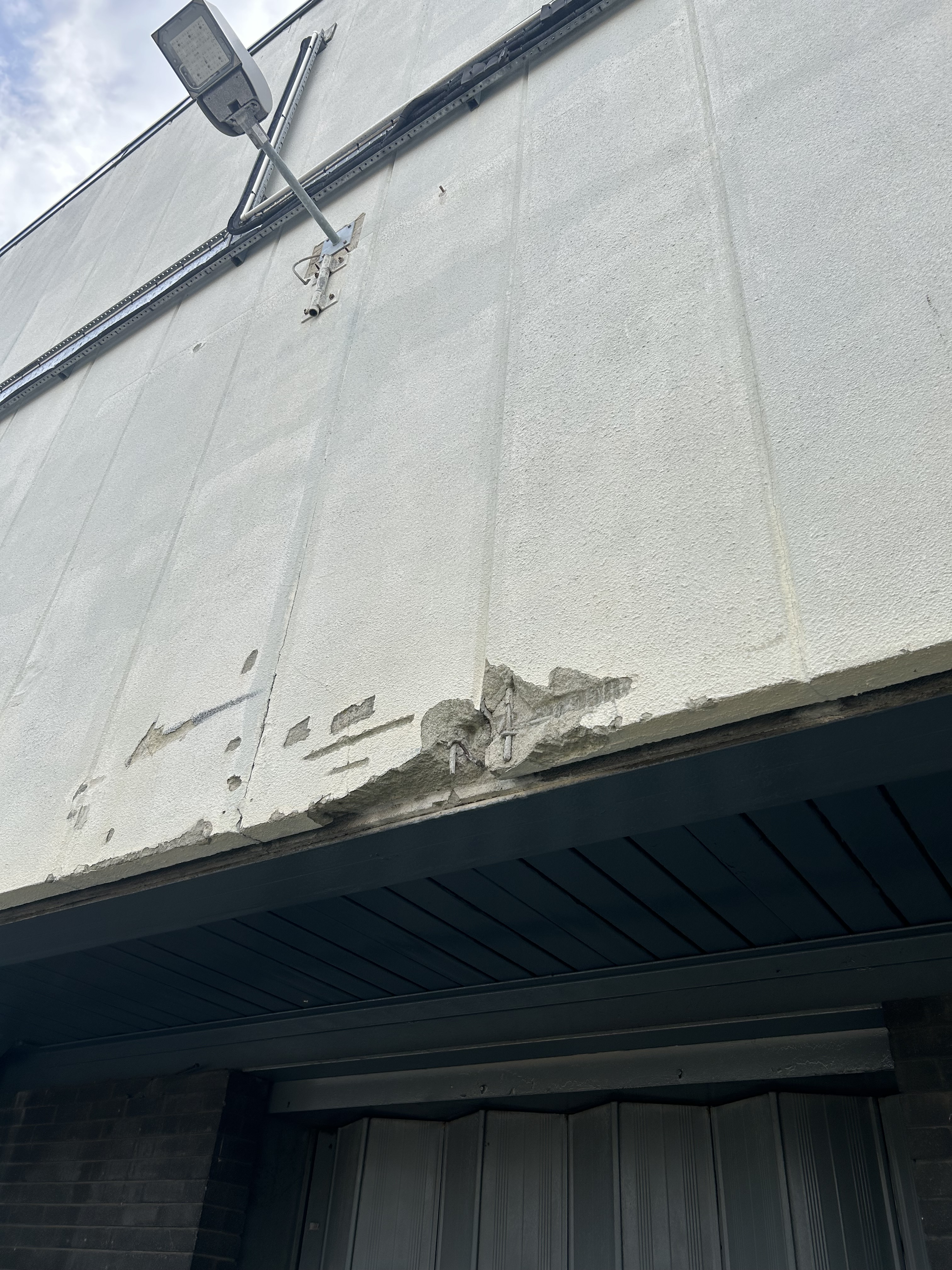
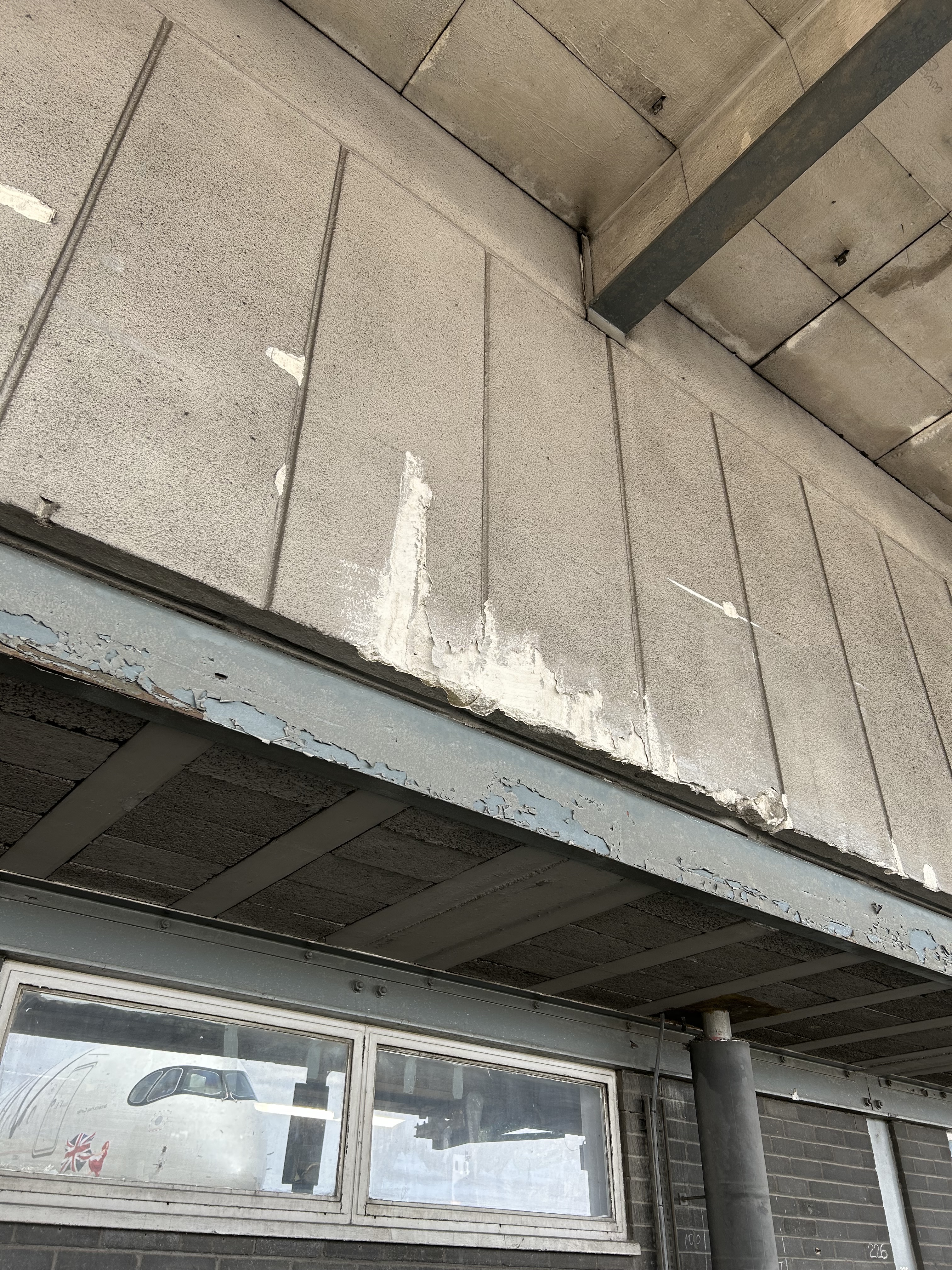
Damaged RAAC panels – not structural…
M25 Junction 10/ A3 Wisley Interchange Upgrade Project
I have recently started phase 2 of the PET course working as part of the earthworks team in Balfour Beatty who are delivering the M25 J10/A3 Wisley interchange upgrade. The project includes the widening of the A3, free flowing left hand turns at every corner, the widening of the existing interchange roundabout, an 8 mile long non-motorised user road and 8 new bridges. There is also an increase in the road furniture and a number of re-wilding projects to offset the impact of the removal of green space along the M25 and A3. A brief overview of the project is below.
Client: National Highways (formerly Highways England)
Contractor: JV between Balfour Beatty and Atkins
Budget: £317 million
Project Start: Summer 2022
Estimated Finish: Summer 2025
Website: M25 junction 10 – National Highways
The earthworks team is responsible for cut/fill, sub-base and temporary working platforms across the whole project. The cut/fill is occurring around sheet piling operations to remove excess material, after existing bridges have been demolished and back filling behind new bridge abutments. The temporary working platforms are used primarily for sheet piling operations, CFA installation and self-propelled modular transport (SPMT) bridge construction. The construction of the platforms to enable these operations is my primary focus at the moment. Some of the temporary working platforms will be used for enabling horizontal drilling operations for services, something that will become a blog post in the near future. Below is a selection of photos of my time on site so far:
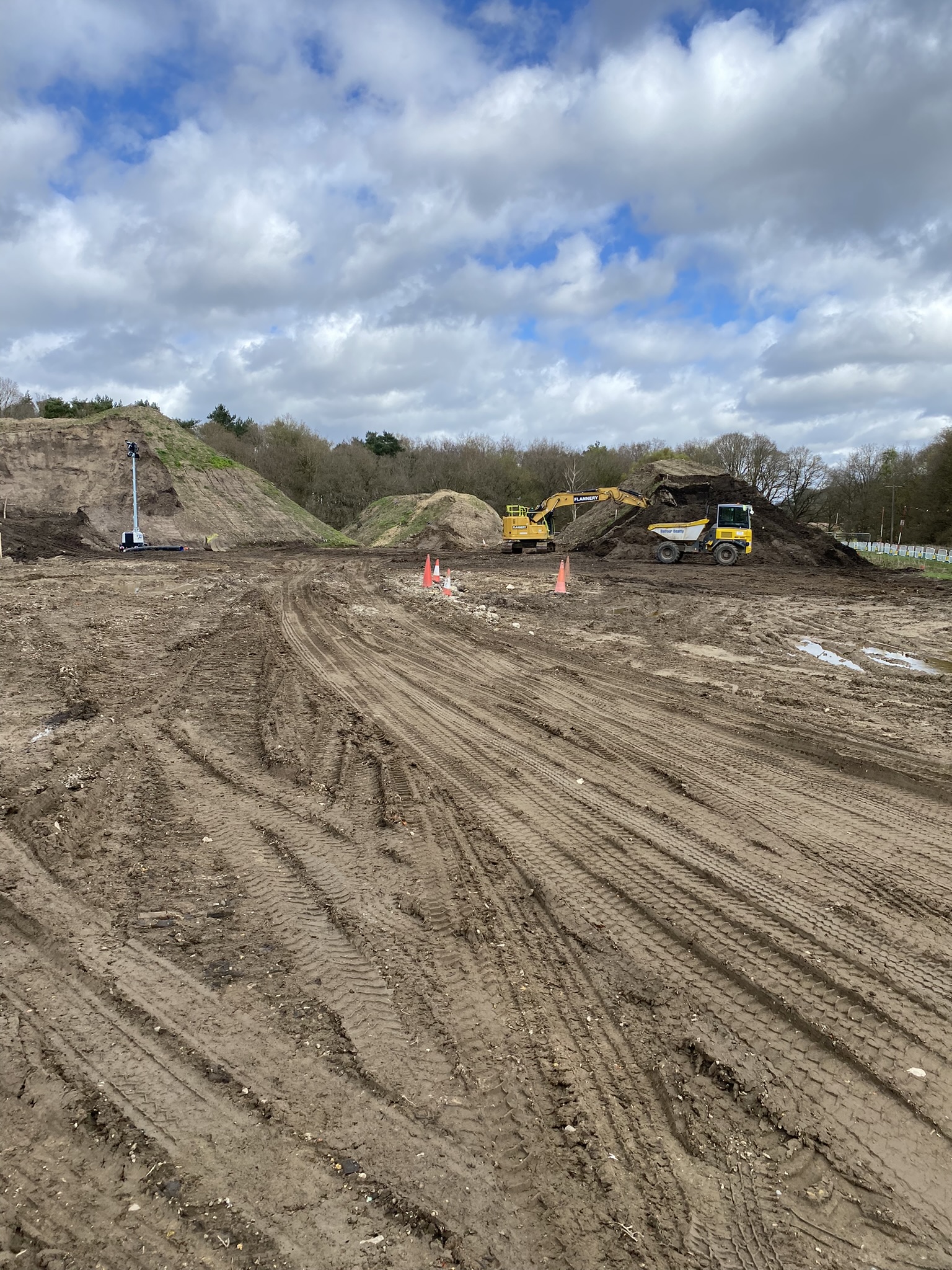

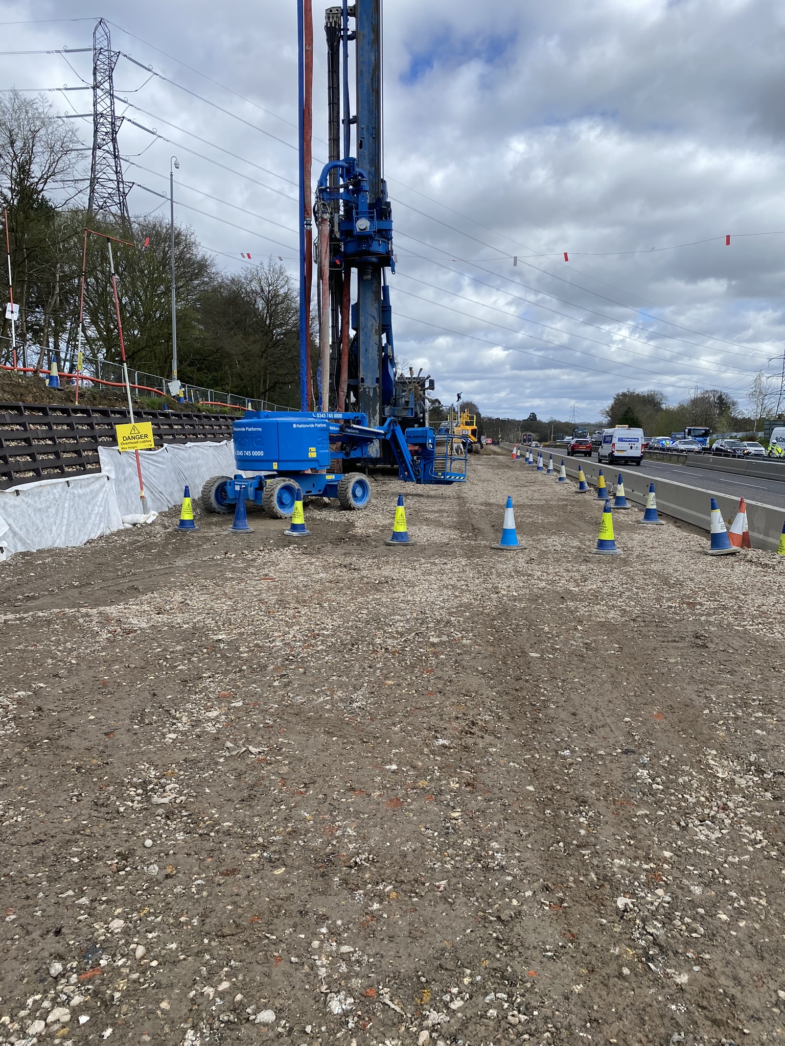
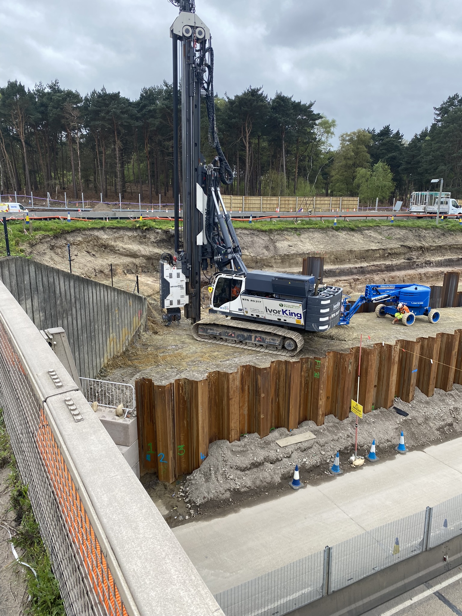
Note: all the photos are from different areas of site but demonstrate the amount and variety of temporary working platforms that are being installed. The sheet piling operations are all temporary works and are being conducted just to install some piled foundations for a bridge abutment. All of that work will be taken out once they have been installed.
A number of challenges have already become apparent on site. As often seems to be the case, there is a disconnect between the designers (who are not geographically co-located with the site team) and the reality on the ground. Some temporary working platforms have co-ordinates that place them in the middle of live traffic which is clearly not a workable solution. Others have half of the platform at the road level and the other half 5 or 6m higher with no scope to batter or step the slope due to site boundaries. When this occurs, a significant amount of time is then spent trying to establish what the designer is trying to achieve and how the platform is going to be used. This involves engagement with designers and sub-contractors so that we can construct something fit for purpose and in the right location.
I’m looking forward to getting more involved in the project; there is a lot going on and I hope to get involved with as much as I can. If you have any questions or would like to know more, please don’t hesitate to get in touch.
