Archive
VR just a matter of clicking the right buttons?
Nothing too in-depth in terms of engineering but this article might be of interest as an overview of where current consultant thinking is with VR.
Green Hydrogen
Clean, reliable and secure energy supply is a key requirement for the further development of the European economy. At the same time, the Paris Agreement and its aim to limit the global warming to well below 2°C call for a quick and significant reduction of CO2 emissions, including the energy sector. In the energy sector this can only be achieved by a significant increase of the share of renewable energy sources (RES). As the most abundant RES, wind and solar, are intermittent by nature, there is a need for energy storage technologies, to provide back-up power when wind and solar output are low and more generally for load levelling and grid stabilisation.
Chemical storage appears to be the most promising long-term energy storage technology. Among chemical storage technologies, hydrogen is expected to dominate as it can be produced by electrolysis of water using excess energy from RES, easily compressed and stored, and finally re-electrified using gas turbines.
Siemens vision for energy

e-Hydrogen is the generation of Hydrogen through electrolysis of water.
The Role of the Gas Turbine
Siemens are currently modifying existing Small Gas Turbine Combustor technology to burn both Natural Gas and Hydrogen for fuel. These Hydrogen and Natural Gas Co-firing Gas Turbines will be able to run on any ratio mixture of Hydrogen and Natural gas, with the desired proportion being solely hydrogen. Natural Gas stores ideally would be used for redundancy or emergency purposes.

Emissions & Closed Cycle
(Civils if you’ve made it this far, cheers)
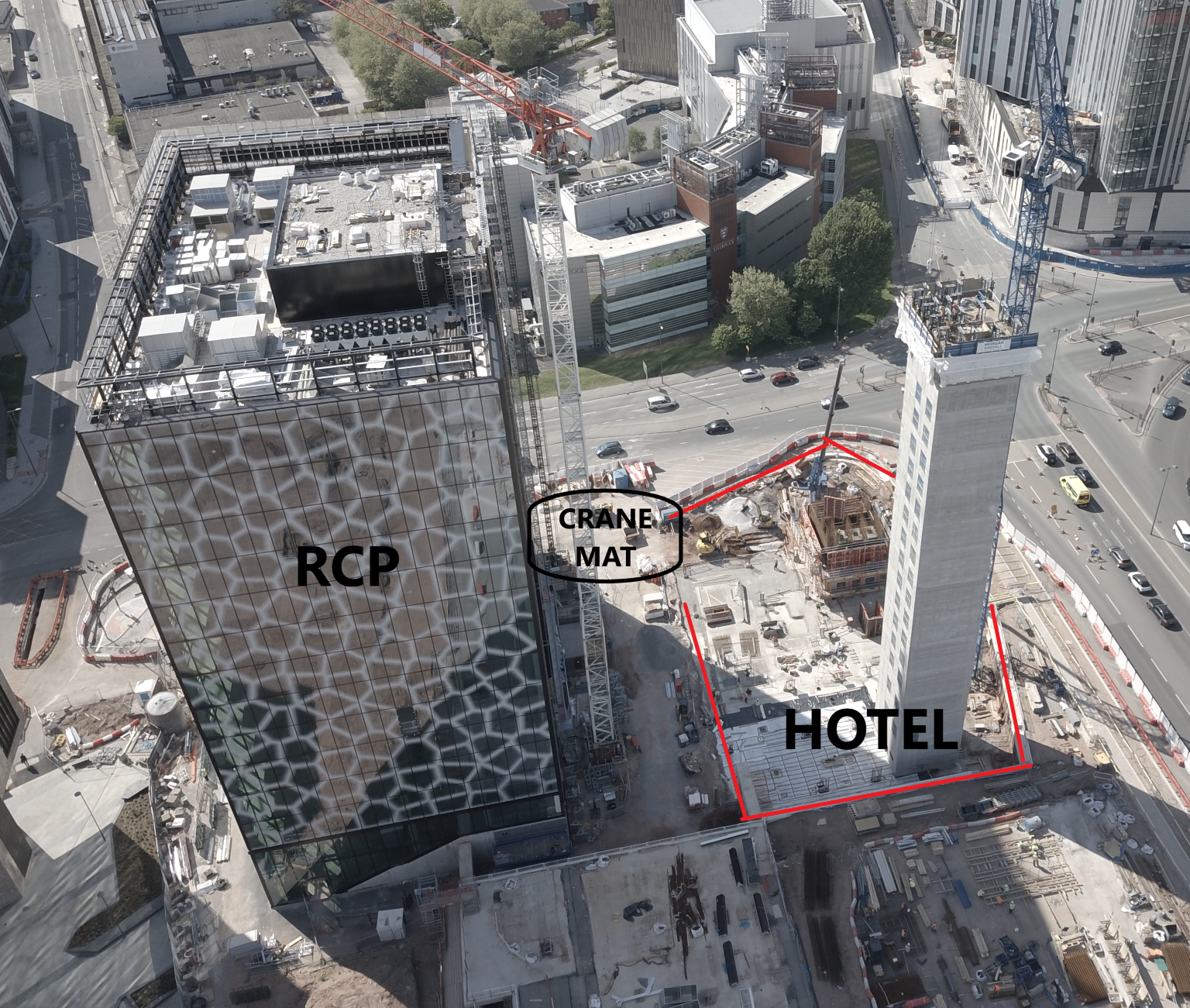
The combustion of Hydrogen in pure oxygen yields water as the only waste product, as follows:
This means theoretically the only exhaust products out of the Gas Turbine will be steam, therefore the intention is to turn the engine into what is known as a closed cycle. Whereby the exhaust steam is condensed to water, and fed back into storage for subsequent electrolysis into hydrogen and oxygen.
The reality is that combustion of Hydrogen in Air will additionally yield oxides of nitrogen – bad. This will drive development of more robust catalytic converters to strip oxides of Nitrogen out of the exhaust.
Further Reading
Concrete Repair Procedure
Sadly E&Ms this is one for the Civils but feel free to read if you want.
This week I was asked to assess a contractor’s proposed concrete repair procedure for precast concrete road barriers (similar to the central reservation barriers on the M25 or M6).
A repair procedure was required because the end stops had slipped during the pour resulting in 10-15mm excess cover at the ends of the barriers. The contractor’s proposal was to saw-cut or grind the concrete back to the design cover so the barriers met the precast dimensional tollerances. Having seen this done on phase 2 site for in-situ patch and crack repairs, I thought it was a reasonable proposal providing adequate H&S measures are employed.
After checking the project specifications for concreting and precasting I found no reason to reject their method. Prior to approving the Contractor’s RFI, a senior engineer reviewed my work and insisted that 3mm (min) of Megapoxy P1 mortar repair grout must applied to any cut or ground surfaces. He explained this is done to the ends of precast super T beams when they cut the prestress strands as 3mm of Magapoxy P1 equates to 50mm of cover.
I can understand why this is done on the super Ts however the road barriers have standard reinforcement (no strand) so is there really a need to apply Megapoxy in this case? I challenged the decision on the basis that it may not be required as that the original design cover would be maintained. In my view the Megapoxy P1 requirement is a potentially unnecessary cost (time and money) to the contractor. I was told if the contractor doesn’t like it they will let us know…
Does anyone have any previous experience of this? Is this another case of ‘this is what we’ve always done’ or is there another good reason to apply a layer of repair mortar?
It’s the simple things that can kill you
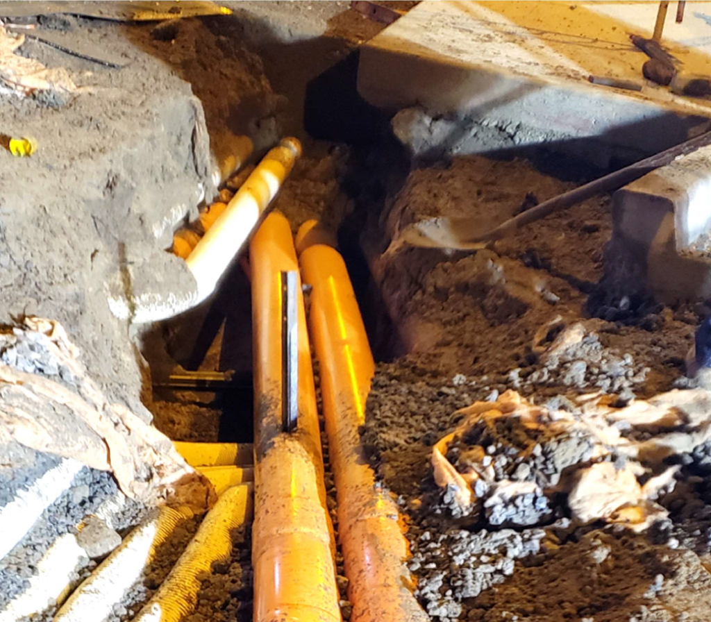
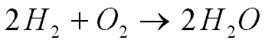
One of the labourers on my site is lucky to be alive. A few of weeks ago he was removing a star picket (think 2-foot picket) from the ground by hitting it from side to side with a sledgehammer. One of the blows resulted in a 1.5m (reportedly) spark coming out the top of the picket. The labourer was unharmed thanks only to the insulated handle of the sledgehammer and his safety boots.
They were removing formwork from a pram ramp which they had built the day before and had no idea there was an 11kV cable underneath them. The investigation has identified a significant number of lessons, but I feel it all came down to attitude.
- The contractors doing the work were complacent and not engaged with the risk management process.
- The foreman had cut corners by getting a labourer to brief the contractors and had not properly read the permit to excavate.
- The engineer wasn’t engaged with the work and had provided a permit to excavate which was hard to read.
- The senior project engineer who had signed off the permit to excavate hadn’t done their due diligence when reviewing it.
All of this was because they had the attitude that the activity was low risk.
Perhaps the most interesting point is that this is the 14th service strike they have had on this job and they hit a 132kV cable on their last one with an excavator. The lessons identified from that are pretty much the same as this one…
This is what we always do…
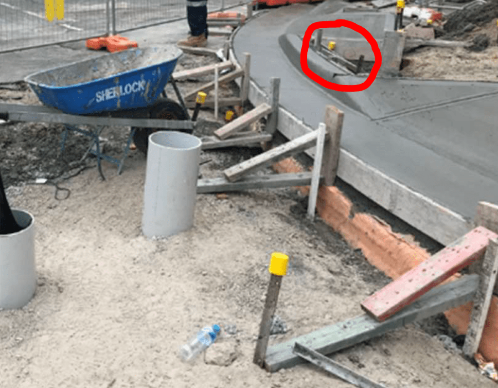
I’m working on the construction of a 17 storey concrete framed hotel for Liverpool City Council. The project is part of a wider scheme of redevelopment that has 10 plots being redeveloped in close proximity. The plot adjacent to my project is a 14 storey concrete framed office building which will be the Northern Headquarters for the Royal College of Physicians (RCP).
The RCP project has reached the stage where its tower crane can be dismantled. As part of this plan a 500t mobile crane will be brought in to lift off the tower crane jib. The only place the mobile crane can set up is across the main access gate to both my project and RCP. This will cause significant disruption for at least the 2 days required for the lifts. In addition to this, 2 days has been allocated to the construction of a 300mm thick crane mat using 120m3 of 6F1.
The ground conditions across the scheme are sandstone bedrock and the area where the crane will set up is a 150mm thick reinforced concrete slab. When questioned if the crane mat was necessary the response wasn’t completely convincing. It seems that a crane mat has previously been used on this scheme and so a consultant has been tasked to design the mat.
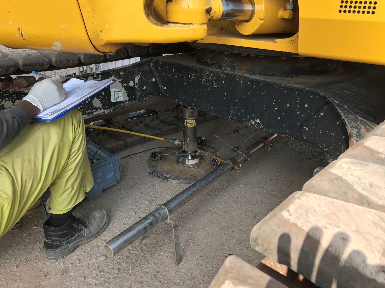
With the prospect of an additional 2 days of delay to my project and the associated Compensation Event claim, it was agreed that plate bearing tests could be carried out to confirm if the crane mat was required. Unsurprisingly, the concrete slab on top of sandstone bedrock proved to be a sufficient base for the crane outriggers. As such, my project has saved 2 days of delay, £14k of overheads for our concrete frame subcontractor, 120m3 of 6F1 and the cost of employing a groundwork’s subcontractor to complete the crane mat. Not too bad for 1hr of testing at a cost of a few hundred quid!
In many ways senior management are ruthless with commercial aspects of the project and exploiting savings and Compensation Event claims. On the other hand, I have been surprised at how unwilling people are to challenge the way we do things on site or question what information the decision was based upon.
Has anybody else been surprised at how unwilling people are to challenge the way things are done?
Who has the force?
I am currently designing a turning dolphin for a tideway project in the Boston Barrier area. The dolphin will consist of steel tubular piles driven into the river bed with a 2m deep RC pile cap. The cap will have a bollard fixed for mooring ships. The dolphin will also require fendering.
Fendering forces (for those that don’t know) are calculated from the berthing energy being dissipated over distance and time. This means that you can only calculate a “fendering force” once the fender has been chosen.
The problem has arisen when deciding the forces on the dolphin. It is BAM Nuttall’s opinion that we should be provided with the forces to expect from mooring and fendering and design a structure to resist those forces. The client has paid for a navsim analysis of the shipping externally and they have provided a line force (fendering) and point load (mooring) for the structure with a caveat that these numbers should be used to validate our own and not be used as a design value. These simulations and calculations were executed with assumed fendering choices and are therefore not really worth the paper they’re written on.
The elephant in the room is nobody thinks it’s their responsibility to provide the fendering solution and nobody wants to stick their neck out and offer up a design value. In our eyes this is a dispute between the client and HR Wallingford but we are caught in the middle. If the client isn’t paying Wallingford to provide us with these forces then why are they paying them? When BAM bid for the design, they did not include the cost of calculating these forces into our quote. This means if we are stuck with having to do it we will need to subcontract this out (as we do not hold the specialty within the department) and will not be able to recover the cost.
As I have no view of the contracts between each party I am simply an outside observer speculating on what disputes may arise from this project. I thought it was an interesting question to ask though about where design responsibility for determining forces lies. Of course we would assume responsibility for calculating wind forces on a hoarding so why not fendering on a dolphin?
The importance of a naming convention and change control.
I am currently working for John Holland on the upgrade of the Bruce highway between Edmonton and Gordonvale.
The project is currently still in the design phase. One of the tasks I have been involved in so far is conducting a take-off from the Prelim Design drawings to compare this data to the estimates at tender. There are significant differences but identifying them has been more challenging than it should be. Chainages are often a standard point of reference on a road job so how hard could it be? What is the chainage of the top culvert in this picture? What is the chainage of the bottom culvert?
Hint: There are 3x different chainages shown on this drawing.

I know there were mixed views on PMQ but in my mind this is a perfect example of where configuration management and change control would be useful. If every culvert was given a name/number it would save time trying to second guess which chainage different teams had used to refer to which culvert. As it stands the drawings, schedule and programme on this particular project are not as joined up as they should be.
COVID-19 Expedient Medical Facility Options Analysis
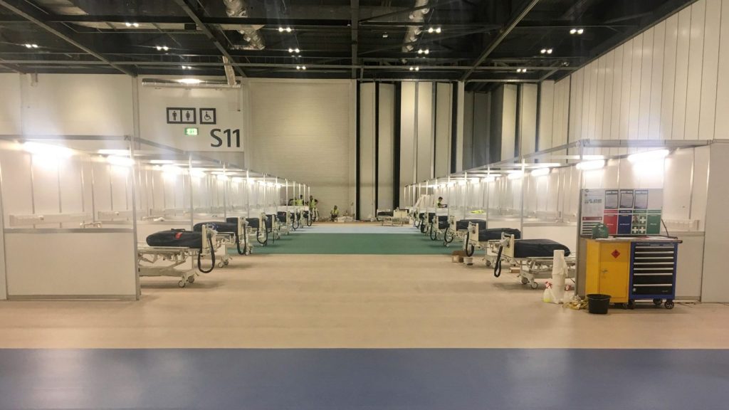
Balancing the requirements of producing an expedient medical facility that provides sufficient overflow capacity whilst achieving the medical and engineering standards for treating COVID-19 positive patients is not an easy task. Compromise is necessary and is evident in the construction of the impressive Nightingale Hospitals that we are all familiar with, see below for a recent blog post by Jamie B.
Over the past couple of weeks I’ve conducted research into the epidemiological nature of COVID-19 and the corresponding medical and engineering requirements in order to conduct analysis and appraise alternative solutions for providing expedient medical facilities. The findings shed some light on the rationale behind the NHS Nightingale Hospitals and the potential for implementing different medical facility options.

The provision of engineering infrastructure should be dependant on the medical requirements for effectively treating COVID-19 patients whilst preventing the further transmission of the virus to health care workers.
However, there is a clear divide in medical guidance for managing COVID-19, this stems from the international community of virologists uncertainty over the causative pathogen SARS-CoV-2 and its exact mode of transmission, is it airborne? Initial research is inconclusive and the jury is still out.
This uncertainty has led to two distinct epedemiological schools of thought for managing COVID-19 patients, the cautious approach and the less cautious approach. The European Centre for Disease Prevention and Control and CDC (US counterpart) strongly endorse the provision of single patient negative pressure isolation rooms with en-suite facilities for confirmed COVID-19 cases requiring admission, where this isn’t possible cohorting of patients is recommended. Whilst the UK Government and WHO state that negative pressure isolation rooms are only required for Aerosol Generating Procedures such as intubation and cardiopulminary rescucitation due to the increased risk of airborne transmission.
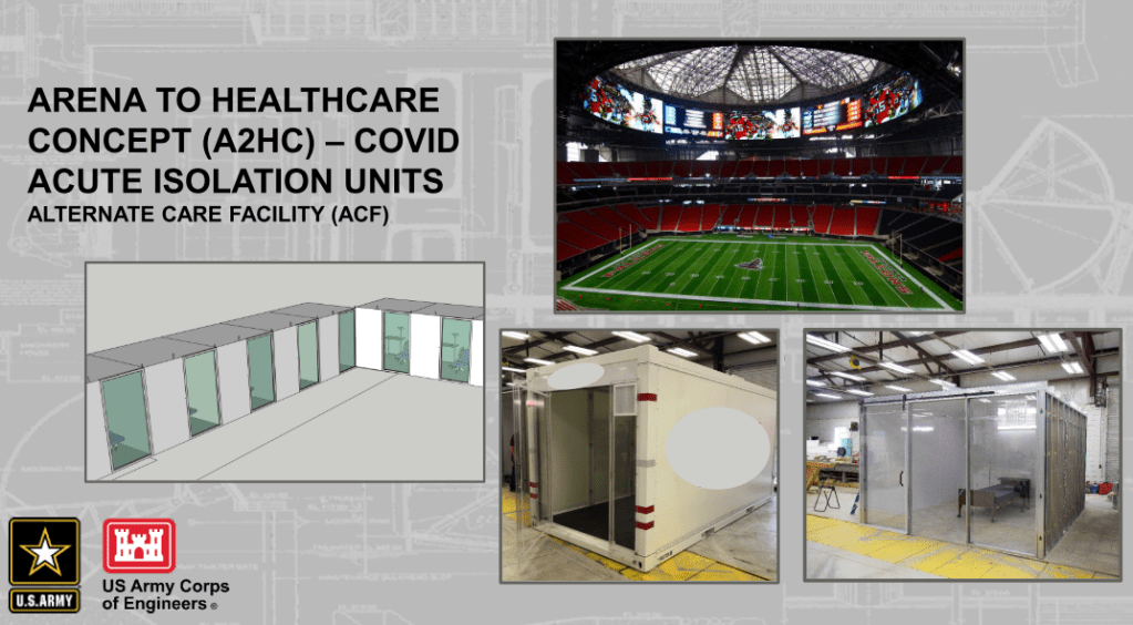
Therefore there is variance in the way governments have chosen to approach the provision of COVID-19 surge capacity medical facilities, see the figures above.
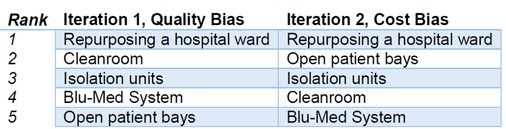
My analysis of the different options has been based on the selection criteria a-f below. I conducted two iterations of a multi-criteria decision analysis (MCDA, a technique used for complex decision making) which allowed adjustment of weighting values, the first with a quality bias and the second with a cost bias (See MCDA findings below). The six distinct options chosen for evaluation were: Repurposing hospital wards, in-Situ construction of isolation units (Design similar to the USACE concept drawing), pre-fabricated cleanrooms, blu-med tented systems and the Nightingale open-patient bay design. See the one drive link below for the full study.
a. Infection Prevention and Control (IPC) Precautions. There is significant variance in the recommended IPC precautions due to the exact mode of transmission being unknown. Systems will be judged on how well they satisfy the most stringent precautions.
b. Ventilation. The system must provide ventilation in accordance with medical guidelines, designed correctly it can contain and mitigate the spread of pathogens amongst other important capabilities.
c. Power. Healthcare electrical installations must provide maximum reliability and integrity of supplies. The ideal facility will have a minimal probability of equipment failure due to loss of power.
d. Construction Time. The medical facility must have realistic construction timelines to meet surge capacity demands.
e. Cost. A key driver in all construction projects, the solution must provide benefits that are justified by the cost.
f. Surge Capacity. The solution must be capable of providing suitable patient capacity to meet surge capacity demands and have a resilient supply chain to ensure operation in the long term.
The findings recommend that in the first instance, general hospital wards should be repurposed to airborne isolation wards. The inherent advantages of locating a COVID-19 treatment facility within a hospital are obvious and there are minor cost-effective changes that can be made to increase transmission control such as adjusting existing HVAC ventilation rates for a negative pressure differential, installation of portable HEPA filtration units to improve ACH within general rooms and minor construction works such as creating ante-rooms and installing germicidal UV-C lamps at entrance points to the ward.
Once existing hospital space has been exhausted there are multiple options. Market research has determined cost per patient of installing a cleanroom ranges from £13,567 – 20,255 per patient with a construction time of 4 person days per patient, whereas it is estimated open patient bays can be constructed at £625 per patient at only 1.5 person days per patient. The IPC precautions and contaminant control offered by a cleanroom are superior (the ones looked at in this study conform to ISO 14644-1 Class 7 and are easily capable of 10 ACH) to the open-patient bay design and UK based companies are offering specialised COVID-19 cleanroom solutions in bulk. As alluded to in Jamie’s blog post it would be extremely difficult to provide adequate ventilation requirements in the ExCel Centre without significant modifications, personalised local ventilation would be needed for effective contaminant control.
Bespoke isolation units that can be constructed in-situ from easily available materials should not be discounted, there are proven designs described in the study that are capable of quick and cost effective construction that utilise portable HEPA units capable of 99.7% contaminant control (referred to as isolaton units in the study). These are scalable and construction materials can be swapped where applicable.
Clearly there are an inordinate amount of factors at play and the nature of the viral transmission is still unknown making decision making more complex, this blog post has only scratched the surface of the engineering challenges of each option. See the onedrive link above for more detail.
This study was completed in isolation with no involvement in the Nightingale hospital construction or COVID-19 planning teams, it is an outsiders perspective. However I hope that it provides awareness of the medical and corresponding engineering issues surrounding the best way to provide COVID-19 expedient medical facilities.
The sixth sense…
At what point in an engineers career is he able to look at a problem and sense that risks haven’t properly been addressed…?
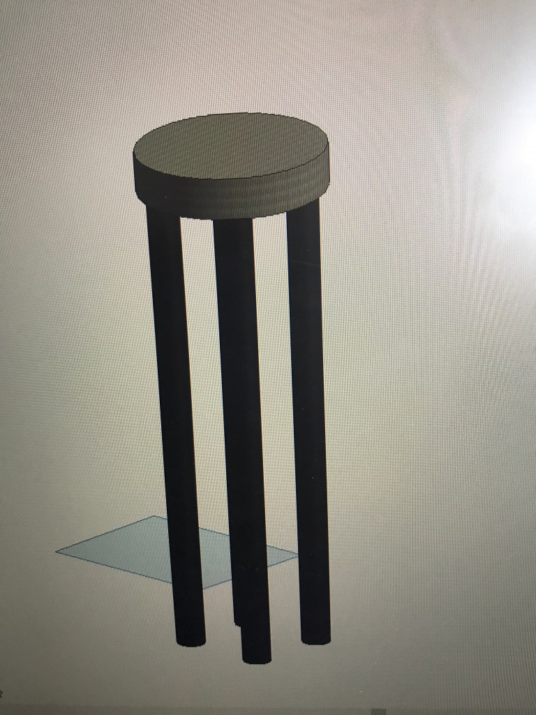
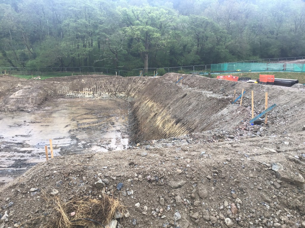
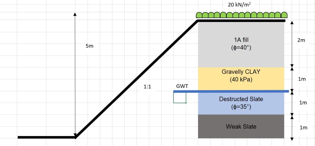
The risk in question here is safe. More specifically, slope stability of the excavation below. The slope is at a 1:1 batter at a height of 5m. The bund at the top of the slope (RHS) indicates the outer edge of the proposed site haul road (not yet operational), which will carry all laden plant. The bottom of the slope is ready for a piling mat for abutment piles. From this, I would suggest a surcharge of 20kPa at the top of the slope. The profile and design borehole is estimated below in the sketch.
Strength properties have been taken from the principal contractor’s temporary works (TW) team for other designs. If is interesting to note that most TW problems to which the site team having varying opinions
The approach/opinion to this has varied dramatically on site. The opinions are: 1) “It will be fine”, 2) “This needs assessing by TW”, 3) This is unsafe”. All project managers (10+ years experience) and all with civil engineering degrees.
What is your gut reaction? for this problem? for other problems? What problems can you rely on your heuristics to address the risks?
Experience is critical but training goes a long way.
My personal opinion (without analysis) is a suitable assessment with either GEO5 and Bishop’s method is required to propose a technical solution and manage risk. Furthermore, I would need to do some re-reading of the rock classification and discontinuities to determine if this is unsafe. I would feel semi-comfortable on doing some analysis on this and making the call on site without TW design. Perhaps a feature of a TMR in the future.
Virtual Visits So Far….
Many thanks to those I have ‘visited’ so far both for your patience and professionalism. I am looking forward to hearing from the rest of you over the coming days. From observation, MS Teams seems to be the optimum but I am waiting on WebEx for a true comparison.
COVID-19 is forcing all of us to work, think and interact in different ways and I am keen that any enduring benefits can be captured. That might be in communications, collaborative working or articulating problems and solutions. This blog offers an element of that and I would ask all of you to embrace it to improve the learning and awareness of all. Little and often is far more beneficial than war and peace every few months. A sketch or photo with a paragraph or two to generate discussion is a good starting point.
On that note we can all look forward to some posts on flooding excavations, permit to dig behaviours and others. You know who you are….
CI
