Archive
Design Risk? Perhaps think twice or double-check…
I’ve delayed sharing this post as I was waiting for the completion of the investigation report however it looks like it will continue for some time. The information in blue italic text is taken from the draft incident report summary prepared by the safety team on site. I’ve also interspersed comments and pictures to aid understanding. This incident is a sharp reminder of design responsibility as we look to transition onto Phase 3 next month. At the heart of the incident is the combination of 5 issues:
- Incorrect design/design shortcuts
- “I’ve done this before/This is how we did it last time”
- Short notice change of plan on site
- Lack of communication between the site team
- The interface between unplanned or different activities on site
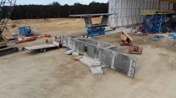
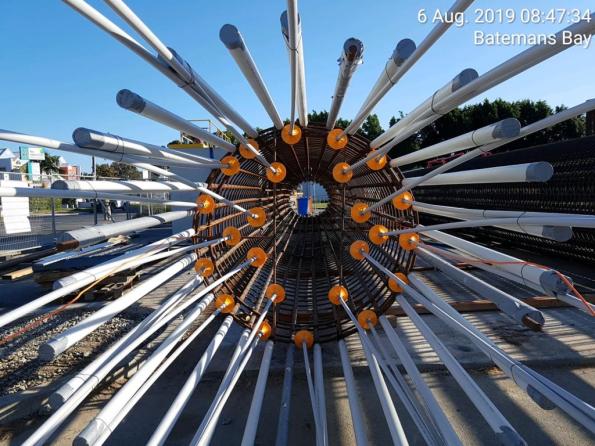
First, a few pictures to whet your appetite to read further…

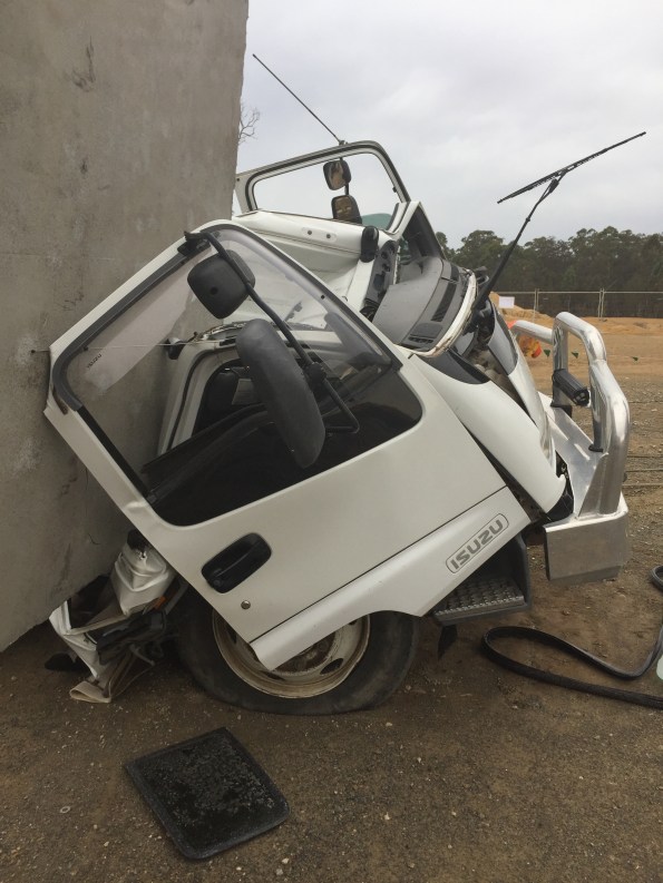

Now the pictures have got your attention I thought I would share a little bit about the serious incident that happened at the pre-cast yard in September. The incident was classified as a 1P incident under the John Holland system. 1 = most serious (deadly consequence) P = potential (fortunately there were no injuries). The incident cost is valued at A$ 100,000
Executive Summary
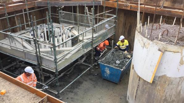
John Holland has been engaged by Roads and Maritime Services (RMS) to construct a new bridge on the A1 Princes Highway over the Clyde River at Batemans Bay. The new bridge will improve access to Batemans Bay and surrounding areas, allow access for larger trucks, reduce traffic delays and improve the Kings and Princes Highways intersection
The project involves the upgrade of approximately 1.55km of Princes Highway between North Street and Kings Highway from predominantly two lanes to four lanes, two lanes in each direction. It includes a new 420m long bridge over the Clyde River, located to the north-west of the existing bridge. The bridge consists of a total of 168 segments currently being manufactured at the projects temporary precast facility located approximately six kilometres south of Mogo.
At 09:00 on Friday 20th, September 2019 a 250-tonne crawler crane lifted Segment P5-1U (the segment) off the transfer table and placed the segment on support pads. The segment weighed 95 – tonnes. The support pad arrangement consisted of three support points, two on one side and one on the opposite side, the pad on the single support point taking fifty percent of the load.
A section of the support pad arrangement is shown below: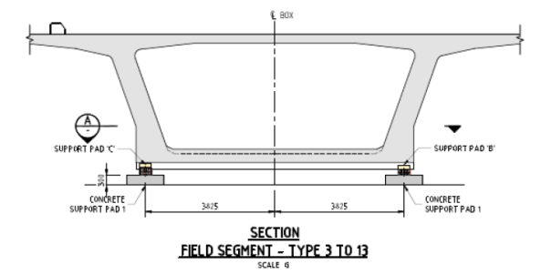
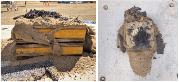
The support pads consisted of a concrete pad with a specified shim arrangement on top; the shims consisted of an anti-slip rubber mat, sandbag, and timber shims made from TRU Form and LVL plywood. Each segment had a specific support pad shim arrangement to suit the segment profile detailed in the Temporary Works 23 design package (TW23).
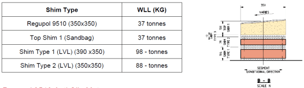
An example of the shim arrangement is shown below. The WLL table was produced as part of the post-incident analysis and was not available on-site prior to the incident.
Segment P5-1U was one of the larger segments cast to date and as a result, was to be utilised during the Straddle Carrier Crane Safe load test scheduled for Tuesday 26th September. The Straddle Carrier WLL was 110 tonnes. The Crane Safe certification test required a test load of 110% (121 tonnes).
On Saturday 21st September, the Precast Manager instructed the crane crew to place concrete pads next to the segment in preparation for the load test. Later the crew were instructed to load four concrete pads onto the Segment. Between 10:00 – 12:00 four concrete blocks, each weighing 2.2 tonnes, were placed by the crawler crane in predetermined locations on top of the segment to achieve the required weight for the Safe load test.
The following table shows how support pad B was overloaded by 28.4% prior to adding the concrete blocks and 40.3% after adding the blocks.

At approximately 12.30 a truck arrived from the main bridge site, returning a spreader beam. The truck driver was instructed by a rigger to park within the radius of the nearby crawler crane. The crane crew unloaded the spreader beam; the truck driver then proceeded to prepare his truck for departure.
I highlight the interface between concurrent activities on site which contributed to the severity of the incident.
At approximately 12.55, almost 28 hours after placing the segment, the truck driver was standing at the back of his truck and heard a noise. Upon looking up, he saw the segment moving at which point he quickly moved further away from the back of the truck. The segment then fell over, landing on the cab of the truck and concrete pads.
The truck driver had just tightened his last truck ratchet strap and was about to get back into the cab of his truck.
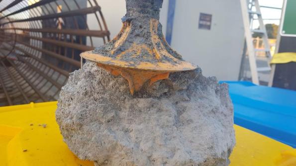
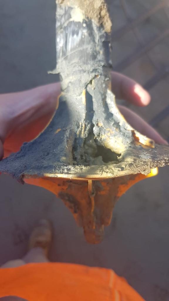
The following picture shows the failed shim. The grey/black material is the Regupol mat.
The Precast Manager immediately attended the incident scene and, having determined no one was injured, secured the area and ceased all works in the precast yard, and made the required notifications.
Key findings:
• The WLL of the anti-slip rubber mat was not checked during design
The design had been used previously on another project in Sydney however the segments on that project had a maximum weight of 70 tonnes.
• There was no technical specification for the sandbag in the design
• The WLL of the anti-slip rubber mat was exceeded by 10.5 tonnes (28.4%) prior to the placement of the concrete blocks (8.8 tonnes) and by 14.9 tonnes (40%) when the additional 8.8 tonnes was added for the Straddle Carrier Safe load test
The issue of the inadequate design was exasperated by a site change to the load test procedure.
• The TW 23 design package was assessed as Low Risk, requiring no independent design certification. Had the risk been rated as “significant” (i.e. by way of Catastrophic consequence and Unlikely frequency, independent design certification would have been required.
• Support Pad inspection on P5-U identified there was not full contact between the various shim layers and the segment. Thus load transfer may not have been evenly distributed across the surface and may have resulted in potential point loading. This may have placed further stress on the anti-slip rubber mats
• The support pad design was not reviewed following initial issues observed with the sandbags during the placement of the segment P5-U
However it was discussed with the Engineers, Precast Manager and TWC.
• Support pad failure was not identified as a risk when planning the Safe load test, therefore no exclusion zone established around the segment.
Hence the truck was directed to park within the crawler crane radius for unloading. This was next to the stored segment.
Actions:
• Establish an exclusion zone around segment P5-U
• Design a temporary support system to secure Segment P5-U, before lifting and reseating on the new temporary support system.
The segment has been quarantined and cannot be used. It will now be crushed for disposal.
• Review Segment Storage Pad (TW23) design and design validation by an independent professional engineer
Works in progress.
• John Holland TEK Team shall conduct a project-wide Temporary Works Audit (3 days)
• Review the Design Management Plan to include the requirements of JH-MPR-DES-003 TEMPORARY WORKS DESIGN AND IMPLEMENTATION
• Review the Temporary Workers Register classifications and ensure design verification and validation is completed in accordance with JH-MPR-DES-003 TEMPORARY WORKS DESIGN AND IMPLEMENTATION
Review and audit of all TW activities and processes conducted by an independent JH team.
• Review [Activity Method Statemet] to include temporary pad installation and segment placement, detail all temporary works design requirements associated with the activity.
• Develop [Task Risk Assessment] specific to the task of pad layout, installation and placement of segments
• Inspection and Test Plan (ITP) check for pad configuration and shim configuration
• Project Wide toolbox discussing the importance of speaking up if you have an issue or concern
• Communicated Change Management requirements to the wider project team
▪ SQE Risk Management
▪ Design Change
▪ Resources (plant, people, equipment)
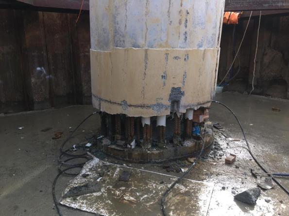
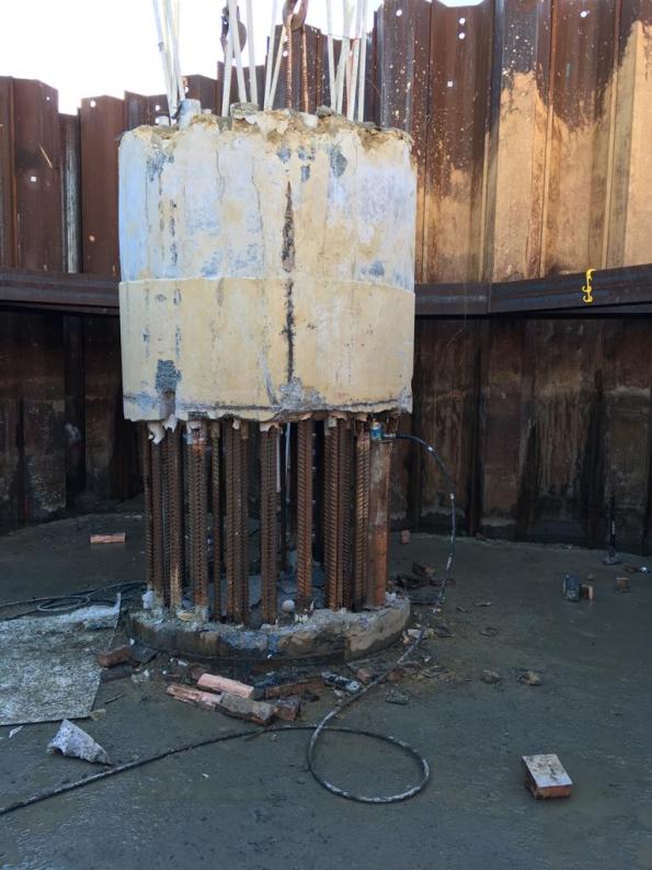
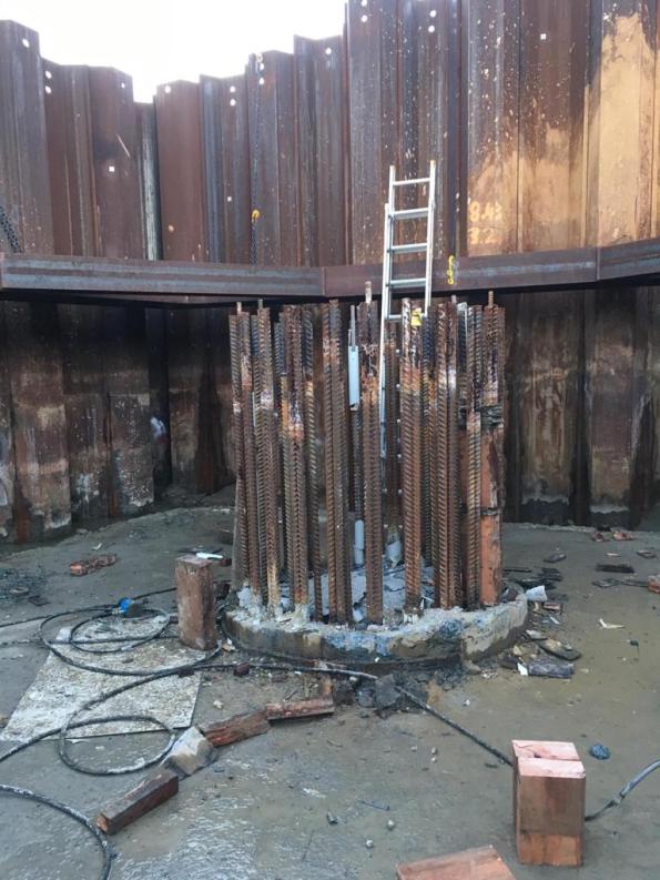
Pile Cap Anchorage
We are currently constructing some pile caps on site. 3,4 and 5 group caps varying between about 1.2 and 2m squared and between 500mm and 1500mm deep. The piles are in place and are being broken out to leave 800mm anchorage standing proud.
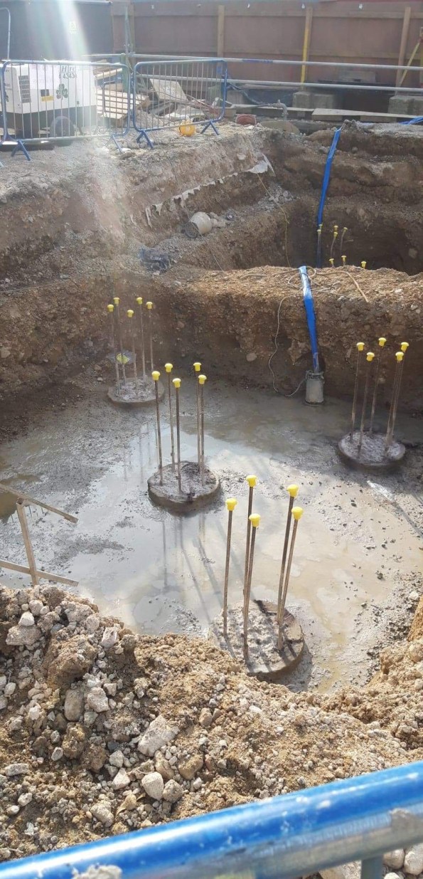
The problem is that because of time pressures the caps are now prefab and dropped in as this is a faster process. The challenge is, how do you bend the Anchorage once an entire cage has been places on top?
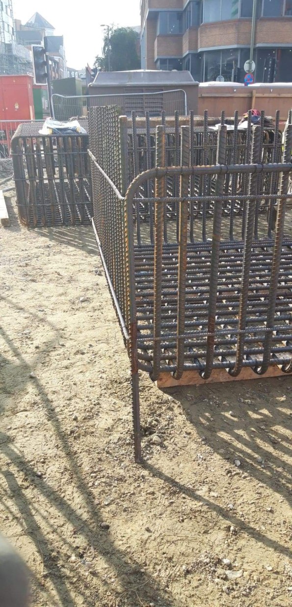
Does the Anchorage NEED to be bent? The 800mm Anchorage does actually stick out above the smaller pile caps as seen below.

Has anyone encountered this and seen a solution?
All hands to the pump
For those that don’t know I am working on a demolition and rebuild project in Woking. One of the main challenges during my phase 2 has been the live shopping centre and services running around and through the site. As John would say RISK!
Well yesterday that risk was realised when the demolition subbie struck a live water main. I was on site minding my own business when I got a shout and went over to see a 6″ pipe distributing water at some pressure. The pipe had been exposed the day before so it could be isolated in the next few days.
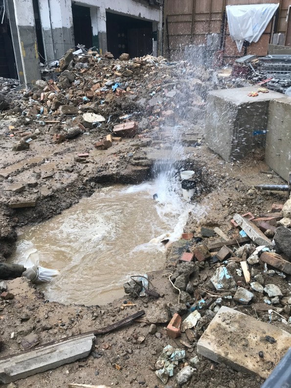
The location of this strike could not have been worse. It is on slight high ground with 3 key low areas around it.
To the left is the demolition site where machines are digging out existing foundations, back filling and constructing a pile mat onto. For those just going through this on phase 1 I’m sure you can reel off the problems flooding a site conducting those activities pose.
To the right ground beams and concrete substructure walls are being cured ready to be back filled and loaded with the GF slab. Again water is not helpful.
Behind is the live shopping centre. As we have demolished part of the shopping centre, the only thing separating the elements and the public is a temporary protection tunnel and crash deck. It has been weathered but would not stand up to a flood, this flooding would mean closing the shopping centre.
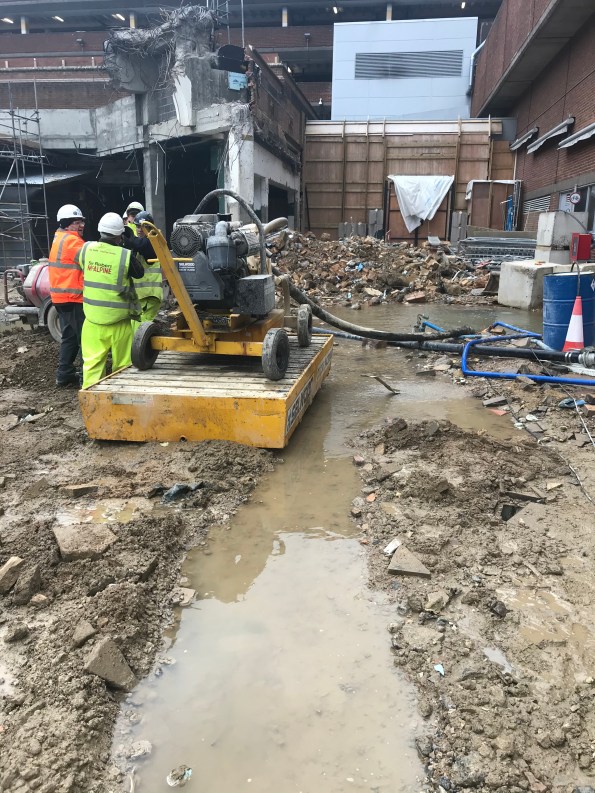
What happened next. Well I instantly went into PITCHPOLE mode and started using demo arisings to create a barrier between the water and the shopping centre. We then had to make a pretty hasty decision what to do with the water so dug a trench to encourage the water along the side of the piling mat.
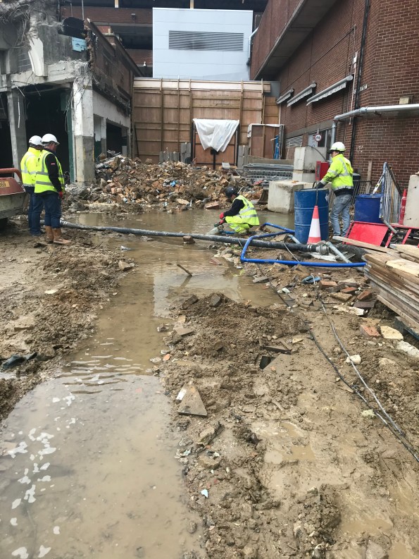
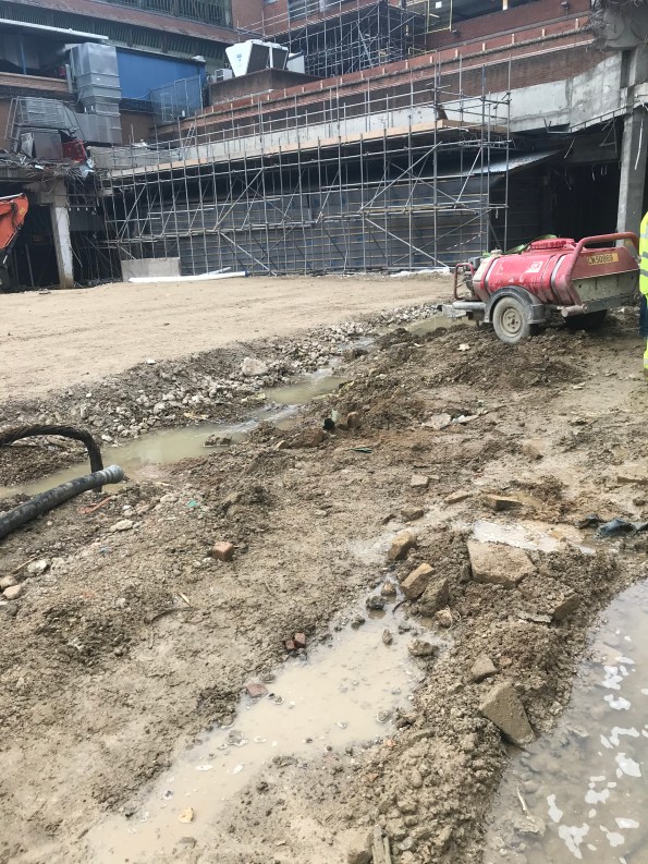
I phoned the M&E engineer for the area and he managed to stem the flow by isolating a valve but couldn’t turn off the entire flow due to it being on a ring main serving greater Woking, they cannot do without water. We made some phone calls and got a large pump on site within 10mins to match the flow of the leak and have stemmed the flooding. Affinity water are not coming onto site until the end of the week so this pump must be run 24/7 until they isolate the ring. 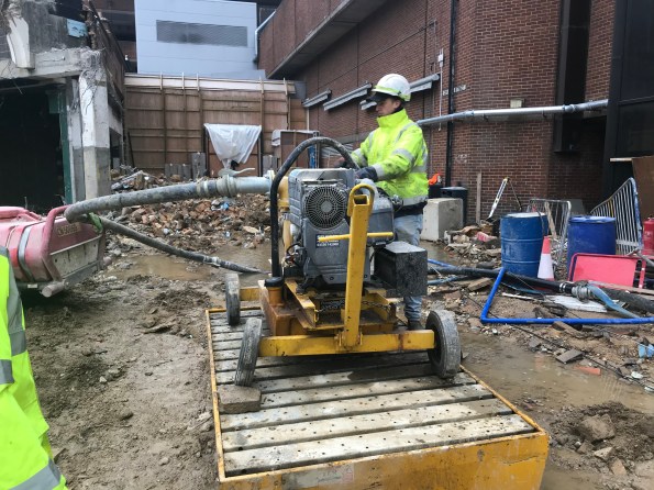
I’ve been reflecting on our actions and the impacts and if we could have done anything better. As it is we chose to protect the live shopping centre and the concrete curing. We have potentially jeopardised the piling mat by diverting the water towards it, a plate bearing test happening on site today may shine some light to whether this has actually caused damage.
I constantly was suggesting leading a trench into a live foul drain and letting gravity help but there is little appetite to do that considering the disruption it would cause to current works. Also there is the consideration of overwhelming the foul system.
How much civil/structural can an E&M manage?
Hey Guys – I hope to use this blog to pose a problem only – generate discussion, and follow up in comments or a blog to let you know what I did about it.
Firstly and briefly – I am attached to the Gold Coast Seaways Project – we are upgrading two pump stations that serve to release recycled water on the Gold Coast out to sea. A map showing project activity can be found below. It consists of two pipelines (northern and southern) and we will have left each of them able to shift future flows of up to 6300 L/s.
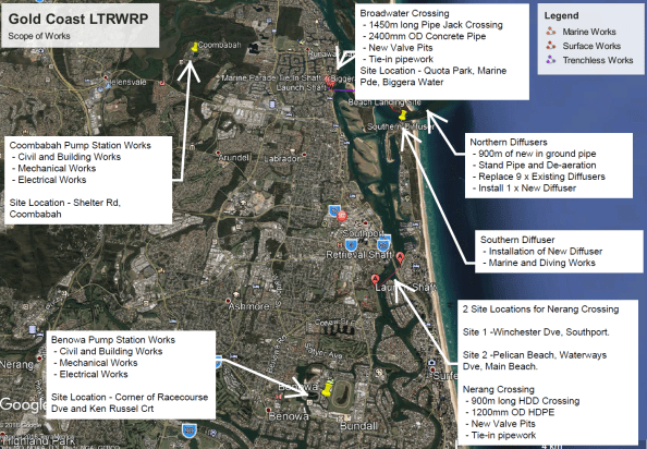
Project overview map
And it is in Queensland Australia……

Sorry
Since arriving on site back in April; I have noted that the Engineers on the Project are flat out and separated from one another by geography as well as function. It is almost like 7 separate projects (each headed by an Engineer) rolled in to one headed by the PM. Meaning that interdisciplinary teamwork is difficult at best. I have made good progress in breaking down some of these barriers and managed to get my hands on to some interesting Scopes of Work(SoW), from a range of areas.
However, as a result I have become the go to engineer for that extra little scopes that no-one else wants, some of which I have politely avoided. But I have picked up some pretty interesting little tasks from underwater construction to lifting with no head room. I might pick up on some of those in a later blog; for the time being structural strengthening!
My main task is to deliver mechanical installation at 2 pump stations; I am teamed with an electrical engineer and a mechanical engineer, but no structural engineer. I have some big pumps and motors to move around the place, some of which have been noted by the designer to exceed the load limits of the existing infrastructure and therefore the preliminary work to the main event (the E&M) is a bit of civil and structural.
This particular task was to install 5 columns and 2 beams to strengthen the mezzanine floor (drawing below) which will be loaded with the new motors later in the year; no big deal?!?!?
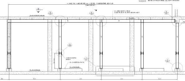
Structural Drawing Snapshot
I was to:
- Read the drawing to put together a scope of works package.
- Submit to potential subcontractors.
- Assess the tenders and award the subcontract.
- Manage the subcontractor through to completion of works.
Problem:
- I don’t know where to start with checking the drawings.
- Any changes I might want to make for practical reasons (clash with my pumps), might not comply with the engineering.
- RFIs raised by the subcontractor will likely push beyond the bounds of PET fundamentals phase.
That said – it’s just management; right? I have done management since joining the Army. This scope is dwarfed by many of the others on the project (magnitude of time and cost) – can I assume that the complexity of engineering is minimal? The designer has already designed it, so I don’t need to do much more than just get someone to fabricate and assemble?
Questions:
- How should I comply with UK SPEC to ‘identify personal limitations, disclose them appropriately and ensure that the implementation of this scope is not hampered by my lack of knowledge’?
- Have you got examples of out of discipline work that you have had to manage?
Finally – it did get installed – and hasn’t fallen down (yet) – so can’t have went too badly.

The Finished Product (anyone spot what’s missing?)
Pile Cropping
posted about how his project was using a mechanical pile cropper to remove the excess portion of the driven pre-cast piles. This method is suitable due to the high number of piles and small diameter of the pile head.
On my project, we have 21 bored piles which vary in diameter between 2.1m and 2.4m. The piles consist of a 16mm thick hollow casing is vibrated into the ground to an established depth. A drilling rig is then used to remove the spoil from within the casing and drill a prescribed depth into the rockhead. When the geotechnical engineer is happy reinforcement cages are secured in place and the piles are poured using a tremie method (to prevent concrete segregation and due to groundwater horizons). This method means that poor quality concrete rises to the top of the pile during the pour (due to laitance) so to compensate the piles are poured a couple of meters higher (‘the overpour’) which is removed as waste concrete. This exposes the reinforcement which is then tied into the pile cap. Due to the large diameter and low number of the piles and the requirement to minimise bending the pile reinforcement a mechanical pile cropping method isn’t feasible.
My project has been using an ‘innovative’ chemical expanding system called Recepieux to break off the overpour at a set level with the overpour lifted off by a crane using pre-installed lifting hooks. This minimises the amount of jack-hammering required pile head and saves a significant amount of time and money. Well at least that is the theory…
To find out more about Recepieux follow these links:
Of the 6 piles the system has been used on so far we have had a 50% success rate. Of the successful breaks, we have struggled to lift off the overpour with a crane so have also used jacks to assist with the removal. A new system on-site often has teething problems and the team have adapted their methods to improve the reliability of the installation, decrease rebar bonding and pre-cutting of the steel casing assist concrete cracking. For the 50% that failed (first 3 piles poured) two weeks of jack-hammering ensued adding delays, noise and dust emissions. The next piles we will be using the system on are marine piles so I’m hoping we have more success as there is limited space for jack-hammers.
Below are some pictures and videos from site:
Recepieux fixed to rebar cage prior to installation inside the casing
Jack-hammering overpour where recepieux was unsuccessful – increased environmental pollution from noise and dust.
Additional labour costs to remove waste and construct access platforms
Recepieux flasks failed to expand as expected
Expanding grout had not had the anticipated effect
Improvements made to recepieux installation resulting in a crack around pile (note the dark black marks are from oxy-cutting the casing to remove it)
Hydraulic jacks were used to assist removal as the crane could not remove overpour due to the rebar bonding to the concrete
Early stages of jacking
Getting closer 60mm at a time…
Overpour removed
(the video makes it look a lot closer than it was…
a number of H&S issues were improved on)
Rebar exposed after overpour removal. Head of pile cap cleaned up and levelled using manual methods
The following document shows the formulation of the above method by the TWC on site: BBB-VSL-DWG-TW-3054-A-
Concrete Testing – Site Practice?
Does concrete on site get sampled for testing in cylinders, 6″/150mm cubes or smaller 4″/100mm cubes? I ask because, although I know what the BS says, I was recently told that site practice has moved towards using smaller 100mm cubes rather than the standard 150mm. No evidence was offered to support this but I don’t wish to tell someone that they are misinformed without some evidence to support my position. What do you know of your site or others you have visited?
How to demolish around a live substation
Demolition on my job at Victoria Square, Woking is now almost complete. The demolition sub-contractor are in the process of removing the existing strip foundations, backfilling and creating a piling mat with the site won crushed concrete from the demolished structure.
We have a few risks regarding the interface with adjoinging structures such as the live shopping centre and adjacent construction but none are more sensitive than the live substation on footprint of our demoliton.
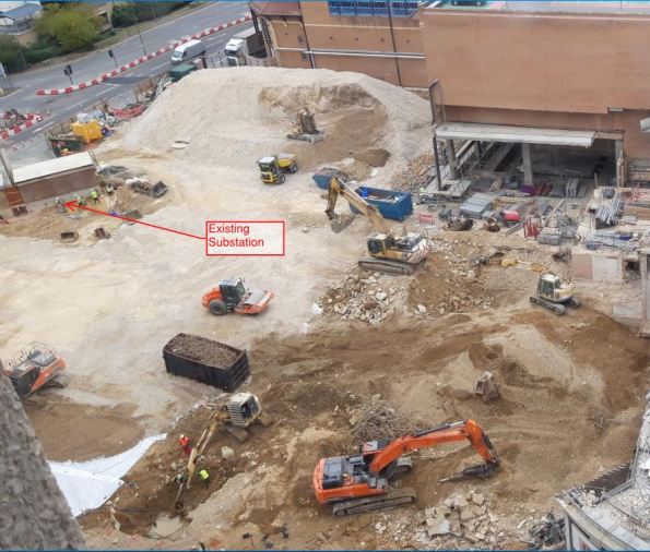
The substation was part of the ToyRUs on the first two levels of the previous structure but feeds a large propotion of the shopping centre and therefore must remain live. UKPN who own the substation have dictated that no vibration above a PPV (Peak Particle Velocity) can be achieved above 5 mm/s and there is a vibration monitor fixed to the substation to ensure this.
The problem is the substation sits on the foundation we need to remove and we are creating a signifficant amount of piles and substructure very close to the extent of the walls.
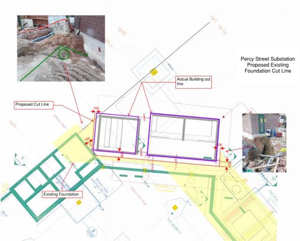
The yellow designates the foundation to be removed and you should also just be able to see the ground beams, pile caps and piles being installed in the coming months. There was the added complication that the exact location of the substation was slightly off during the design of the new structure (compare the grey lines on the drawing to our overlaid purple lines) which make these tollerances even tighter.
The vibration of installing piles so close to the substation is being mitigated by use of a CFA method (although this was always going to be the chosen method anyway as it was selected for the rest of the site) but it still leaves the problem of breaking out a 1.5m deep reinforced concrete foundation 150mm from the substation which isnt allowed to experience vibration. The solution…


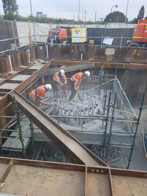
Diamond stitch drilling. By using a 150mm diamond drill bit and drilling along a given line around the substation overlapping the holes creates a seperation of 150mm of the foundation under the substation and the foundation to be removed. This is an incredibly slow process with each driller completing less than a metre a day each. With 4 operators on site this will still be nearly 2 weeks work.
In the photo you can see 4 drill rigs set up as the drill out cores of the foundation. It hasnt been raining that soggy foundation is caused by the amount of water used to keep the drill piece cool.
I still have my reservation on whether this will prevent vibration when it comes to removing this foundation considering I feel it in the site office, but it shows we are taking practicable measures to comply with UKPN targets. Whether UKPN have set unreasonable targets is a question for another time I guess, a quick bit of research told me that structures can normally resist up to 20mm/s but I dont have a full understanding of sensitivites to generators or transformers that may be inside.
Changes to Journal access
A little off topic but this is probably the easiest way to get the massage out to everyone in terms of thesis research (well most of you!!). Cranfield have moved from Shibboleth to OpenAthens in terms of sign in for Journals – hopefully you have noticed this and the lack of e-mails back mean that your access is working OK. If it isn’t the case then you can contact libraryresources@cranfield.ac.uk and let them know the sites you are trying to access.
Access to journals will be a crucial part of your thesis literature review so please don’t leave it too late.
Unexpected Depth
I’m currently the Project Engineer overseeing the construction of 2 large pile caps (2 of many pile caps across my scope) for the main bridge crossing the Maribyrnong River in Melbourne, part of the West Gate Tunnel Project. We are aiming to start pile cap construction on completion of piling.
We had an interesting pile refusal I thought I’d share and get some feedback on?
Given the size of these particular pile caps, it should provide a unique experience into the construction process and QA. To give an idea of the pile cap sizes and loads being transferred from superstructure into the ground, each pile cap consists 46 precast piles, each 34m length. Due to the length of these piles, each pile is made of 3 segments, spliced in two places. The bottom segment is 10m long with the middle and upper sections 12m long. Each pile cap will consist 370m3 of concrete (16.6m x 7.2m x 3m deep), 108T of reo and will have post tension bars protruding out the pile cap and up into the precast column – a feat in itself to ensure correct lengths were procured with threads considering elongation lengths (3-6 month lead time required due to fabrication in South Africa) and potential clashing with pile cap reo; we are currently conducting 3D modelling to detect any clashes.
During piling this week, everything was going well until a single pile refused well above the expected depth – piles are driven to a layer of basalt rock approx. 32m deep and are considered end bearing. Each pile is designed to take a geotechnical design load of 2900kN, which is very high for a precast pile. The pile in question can be seen below. The variability of the basalt rock layer can be clearly seen.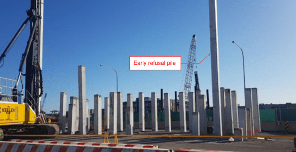
e believe the pile has refused on ‘floating basalt’ (i.e. a large basalt boulder in the upper silt layers). Because it has refused on the basalt, it has the required ultimate geotechnical capacity of 3867kN (note this is the 2900kN with a reduction factor applied – a different approached used under Australian Standards from that used in EC7).
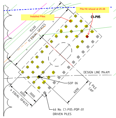
Pile cap Plan
We can’t just crop the pile at the current depth for a couple of reasons. Firstly, the top splice joint is 0.5m below pile cut off. Under VicRoads 605 (Driven Piles) publications, a minimum depth of 5m is required for splices, due to durability (a blanket requirement that doesn’t seem to consider soil properties at individual sites?). Also, I believe this depth ensures bending moments, which are increased near the top of the pile, are not too excessive at spliced joints.
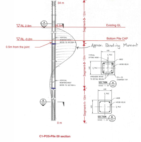
Refusal Depth and Estimated Bending Moment
The other issue is that the steel reo in the middle section pile is not sufficient structurally to transfer load from the pile cap to the pile (top segments have almost twice the reo).
As the pile has reached geotechnical capacity, I believe a replacement pile need only be required to add additional structural support (i.e. shear and bending capacity) – i.e. install a top segment pile as a floating pile next to the refused pile, providing the structural capacity required without carrying any geotechnical load.
However, the decision was taken to install a longer pile (matching the refusal depth) using segments with adequate reo. This, to me, seems slightly more conservative given geotechnical capacity was proved? Either way, the importance of getting a decision signed off quickly was paramount to allow piling to continue and keep on schedule – a decision was made within 24 hours.
I’ll upload a blog once these pile cap begins construction!
Where is the real critical path?
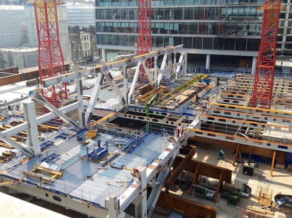
Being a steel framed building it won’t surprise anyone to hear that the erection of the steel frame is the current critical path activity on my site. On the face of it, all is going well; steel is flying into place and the fixing gangs are able to knock off at 2pm every Friday to head back up north for the weekend. There is no evidence of surplus steel on the site and almost everything is installed the day it arrives, leaving the lay down areas empty. All good, yes?
Unfortunately, no. While the installation can run like clockwork, the real critical path on this project is more than 200 miles away at the fabrication shops in Bury, Lancs. The volume, weight and complexity of the members being installed in the early phases of this job have the fabricators running to max capacity and, in essence, they are failing to provide steel to site quickly enough. This is resulting in considerable delays that are out of the hands of the sub-contractor’s site management teams. In an effort to understand the problems they are facing we headed north for a tour of the fab shop turning out the biggest bits for the job.
E&Ms can probably dip out of this one now with the fortune cookie take-away that the critical path isn’t always where you think it is and off-site manufacture is vital to the programme. Anyone else can carry on for a photo-heavy tour of the fab shops and what the pieces look like on site.
INTRODUCTION
To set the scene for our visit to Bury: the early stages of this project build are 6 parallel ‘launch’ trusses which support the erection of an arch, together spanning between a pair of columns which are cast into large diameter pile heads. The trusses are two storeys tall (between level 1 and level 3) and the arches join at level 10. Each truss alone weighs around 1000 tons and is over 60m long. Pieces are manufactured then brought to site to be bolted together to form the truss.

Structural skeleton showing 6 arches through the building above the launch trusses.
When (almost) complete the launch trusses should look something like this:
Launch truss approaching completion with top chord fitted along the central section.
So how do we get to this point?


Steel arrives at the fabricator as either rolled sections or plate which are then cut to length and brought onto the shop floor for fabrication.
BASE PLATES

Work on the column bases starts with the base plate which has a shear key and reinforcing cage welded to the underside.

Plate sections are welded along their length into girder or box sections then welded to the top side of the base plate.

For simple runs semi-automated submerged arc welding can be used. This puts down more weld metal than hand-held options and is easier on the operator for numerous straight runs. Note the angles tacked onto each end of the run to allow the machine to over-run then turn around. These are ground off afterwards.

Girders are welded to the base plate before bracing and stiffeners are added. All pieces are then QA tested and dispatched to the paint shop.

A ‘standard’ column base installed with intumescent paint. The rebar on the underside laps with bars protruding from the pile cage, within the casing. The shear key is then concreted into place, pouring concrete through the mouse hole in the base plate seen in the pic.
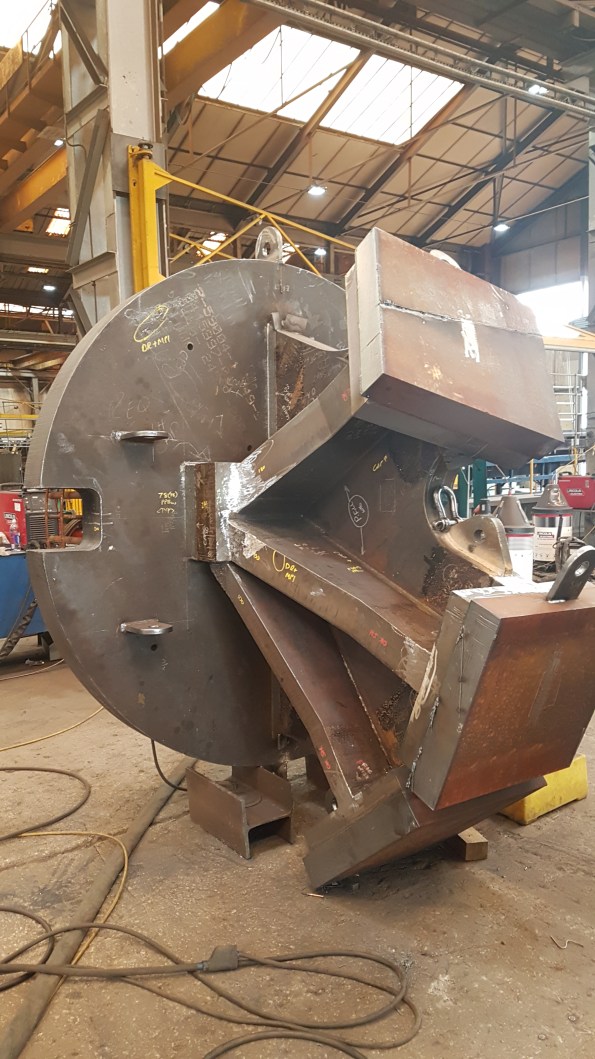
This is one of two special base plates which will support a tripod of box sections in one corner of the building. If the three column bases were ‘fingers’ the web between them is a single piece of plate steel, cut with the design curves and welded to the base plate. The column fingers are then added on either side and the caps applied. In this photo, from bottom to top, the ‘finger’ plates are 100, 150 and 180mm thick steel plate. The knuckle at the bottom is 240mm thick.
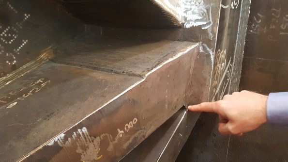
FPBW where a ‘finger’ meets the ‘knuckle’ in 150mm plate. Starting from inside the bevel (as pointed to in the pic) this weld required around 800 passes by the welder, by hand.
The complexity of some of the columns gives some explanation for the timelines required for their manufacture. This latter ‘special’ column has been in fabrication for 6 weeks and will spend at least another week being shot blasted and painted on it’s way to site. One of the columns was found during QA to have a lamination issue (layers of steel forming the plate pulling apart from each other) so had to be made again from scratch – rushed through production at best effort it has arrived on site today, 5 weeks behind its initial schedule.
COLUMNS
The columns, or column head nodes, which sit on these bases are fabricated box sections. In order to transfer load across the whole area of the capping plate, the surface needs to be exceptionally flat. The sections are fabricated and prepared then milled to achieve the desired tolerance for on-site welding to the column base plates.
Column section after fabrication, awaiting milling.

Milled column bearing end showing the bevelled edges to allow butt welding on site.
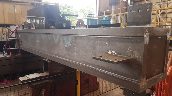
CHORDS
The launch trusses have their principal chords at level 1 and level 3. The lower is erected first, spanning on temporary works, and the upper chord is added afterwards with the tie members. The fabrication of these complex members is time consuming and mistakes in the fabrication could set the project back weeks.

To create the truss nodes girders are combined and web stiffeners added.

The preferred weld type is full penetration butt weld (FPBW) but the steel needs to be extensively prepared to allow this process. Incoming plate needs to be bevelled to allow the full penetration of the weld. The weld metal then returns run after run to fill the bevel and create the joint (finished example on the left side of this pic). The hole in the web (called a cope hole) allows for continuity of the weld through the web; without it the right-angled joint between web and flange becomes a stress concentrator.

The finished article (almost) awaiting dispatch to the paint shop
ERECTION PROCESS
Once fitted to the pile, the standard truss columns will have bracing and a column head node either bolted or welded to them to support the lower chord of the truss.

Lateral and diagonal bracing on a column base plate

The column head node connecting, in this case, three adjacent piles. This was the first to be built to provide maximum stability to the frame while the lower launch truss chord was installed. This single lift was in excess of 20 tons, testing the limits of the tower cranes on site.

With the head node and back span (right) in place the lower truss chord was connected (left)
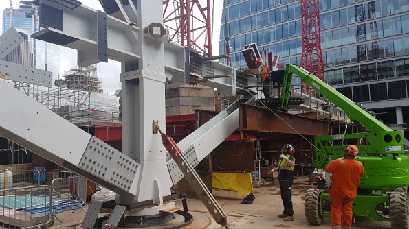
Making the splice connection for the first full span across the site.
Some weeks later the top chord is added with the tie members
SUMMARY
No amount of additional effort on site can speed up the construction process when the supply of finished members to site is insufficient. In this case the fabricators are working well and produce high quality products to site; unfortunately they are at max capacity and supply is still not meeting demand. With no float in the fabrication programme set backs hit hard and delays are felt to their fullest with the repercussions being felt on site.
For my part, I would advise anyone to get out and see their off-site processes (whatever they may be) whenever they can. Not only does it humanise the process, it is a vital part of construction that should be fully understood throughout the supply chain.
