Archive
The HAJ waste water treatment facility at HPC.
This will not be as long as any of Mark’s blogs
A large part of my time at HPC has been as the construction delivery manager for the temporary waste water facility, known as the HAJ. Designed to accommodate a peak flow of foul water of 33.8L/s for a peak of 9,775 construction workers. It achieves this through the 3 modules each consisting of a Primary Settlement Tank, Rotating Biological Contactor, Final Settlement Tank and a UV filter. Effluent from all 3 modules will flow into a final effluent pump chamber that pumps to a main header tank discharging through a pipeline of the end of the jetty. KBJV are the Tier 1 contracted to complete the Civil and M&E works, they have sub-contracted the main M&E installation to TES, a contractor from Northern Ireland who have in turn contracted much of the electrical work to Mike McDonald electrical services. Much of the plant is of the packaged variety supplied by KEE wastewater treatment technologies.
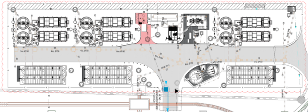
I arrived on-site after the main civil works were complete just in time for the M&E install, when I encountered my first issue (the first of many); feeder pillar 109.
Firstly, the loading profile for the facility was stated as 600kVA requiring 2 x 300mm^2 cables to provide the supply. I noticed this was very large and queried the value with SET, through investigation it was found that this was a typo with only a 60kVA load required. I proposed that one 300mm^2 cable would suffice to meet the demand and allow capacity for any future expansion. The orientation of the pillar was also incorrect as can be seen from the images below and KBJV also used a 90 degree bend which was too tight a radius to allow the cable to be drawn through! TES, the Tier 2 contractor tried to play a contractual game stating that the change in cable size would result in a change in the specification for a number of electrical components within the facility. They did this to try and buy some time as they were (and still are) behind schedule. This was solved buy instructing them to increase the outgoing cable from 95mm^2 to 120mm^&2.
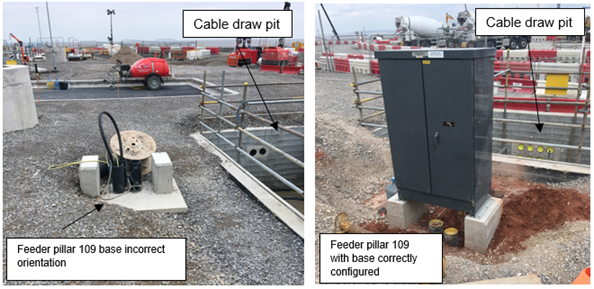
Having changed cable sizes I requested a grading study to be completed, TES and KBJV initially did not see the point, proving the the change in cable size would not cause any issues regarding the protection scheme, seen below. The end result is that all issues were resolved, but I learnt that competent contractors are not really competent and that you have to double check everything.
.
Temp PT
Tom, I’ll keep this one short just for you!
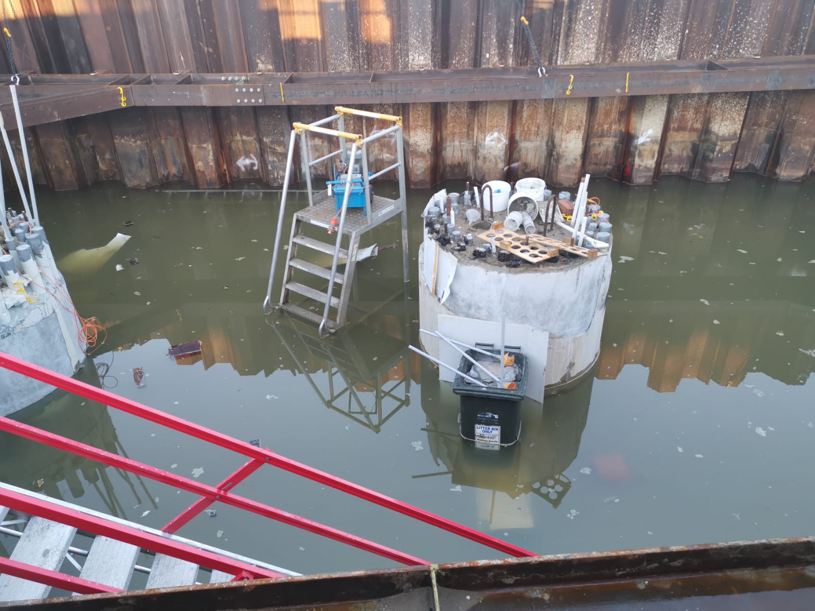
I’m currently writing a SWMS for the installation of 98t precast pile cap shells onto the marine piles. The idea is a RC precast shell is constructed on the foreshore and the steel working platform installed prior to the lift. Once in position, the gaps between the piles and the shell are grouted with underwater grout and the water removed to create a working area to remove the pile overpours and complete the RC pile cap. The working platform is then used to support the TW access platforms for the pier construction.
It seems quite a clever and well thought through. There are only a few challenges to the plan:
- Piling and pre-cast shell tolerances require a larger hole in the precast pile cap shell than the pile casing. This will let water in.
- In order to seal the gap between the pile casing and precast shell a seal is required to prevent environmental contamination of the river a seal is required. This will need to be positioned and removed (ideally without using divers due to cost). You can buy inflatable ring seals for this purpose but in true Blue Peter style we are making our own from plywood forms and rubber extrusion seals (think large car door seals). We have been doing lots of discussing and sketching of ideas in the office so I look forward to seeing if it will actually work.
- A method to lifting the precast shell and suspend it in the correct position is until permanently connected to the piles is required. This is what I want to blog about.
To lift the precast pile cap shell two lifting beams have been fabricated (each beam is made from twin 457 x 152 UBs joined together with additional stiffeners, bearing plates and lifting lugs). To suspend the shell at the correct position three hanging beams (same design as lifting beams) are used and will fix to the pile casing (2100mm diameter steel CHS 6mm thick). To counter the uplift forces a hold-down bracket and clamp system is proposed (but unworkable as we can’t source the required clamps) and are requesting a design change.
The shell lift will need to be conducted in two stages. The first using a 400t land-based crawler crane (with maxer) to position the shell closer to the river bank. The second stage will use a barge-based 400t crawler crane (with maxer) to pick up the shell and position it onto the piles. The problem is how do you stop the concrete being subjected to tensile stress?
The solution is temporary prestressing. The design includes 10 No. 40mm diameter prestress bars anchored into the shell wall below the lifting/hanging beams. A number of load cases have been examined which determines the lifting case is the most critical. To prevent the development of tensile stresses the bars were initially due to be stressed to 670kN to give a retained stress of 500kN after prestress losses (mostly due to lock-off). Further calculations indicate the concrete shell would fail if the bars were stressed to 670kN so the pencil has been sharpened and a new prestress limit of 470kN is proposed (300kN retained stress). This is still undergoing verification but as the pile cap shell base was poured last week and the walls are being poured tomorrow things could quickly change.
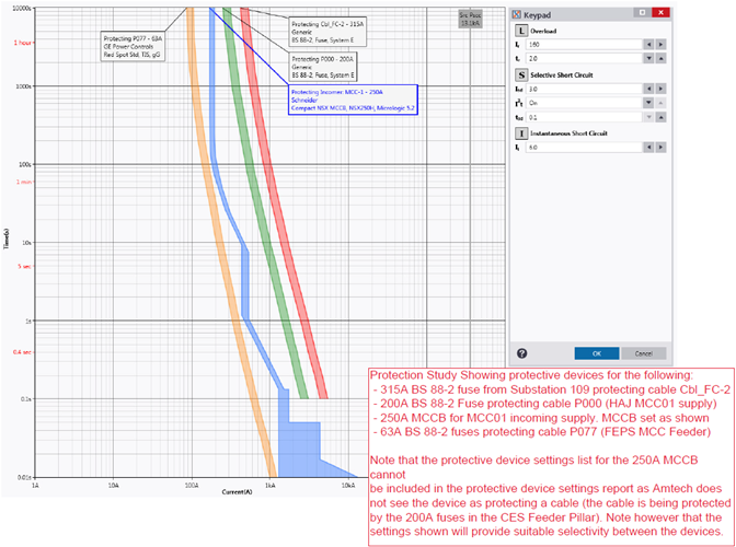
I thought this was an interesting use of temp PT by VSL who specialise in PT (as Freyssinet’s main competitor) so I hope you enjoyed the read. Below is the proposed construction sequence and precast pile cap shell drawings (temp PT highlighted in red boxes).
Planned construction sequence:
Stage 1 (not shown) – install sealing rings.
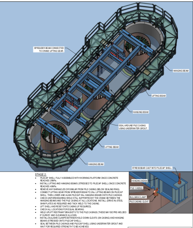
Stage 2 (above) – Lifting pile cap shell onto piles. Model shows lifting beams, hanging beams and temporary working platform.
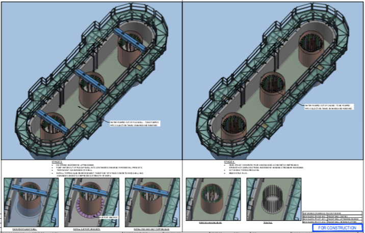
Stage 3 (above LHS) – Removal of lifting beams and sealing of gaps and removal of water.
Stage 4 (above RHS) – Second stage slab pour, removal of hanging beams and removal of pile overpour and excess casing.
Stage 5 (not shown) – Complete pile cap RC pour
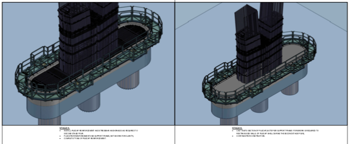
Stage 6 and 7 – Construction of bridge piers (additional working platform construction not shown).
Pile Cap Shell Drawings
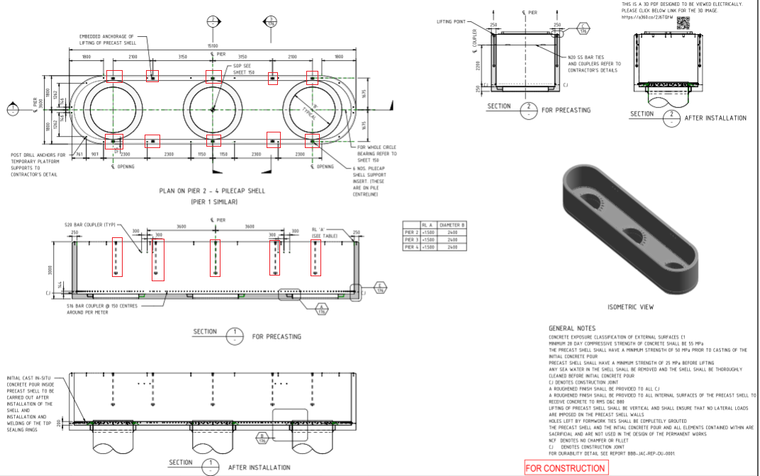
Pile cap shell drawing (above)
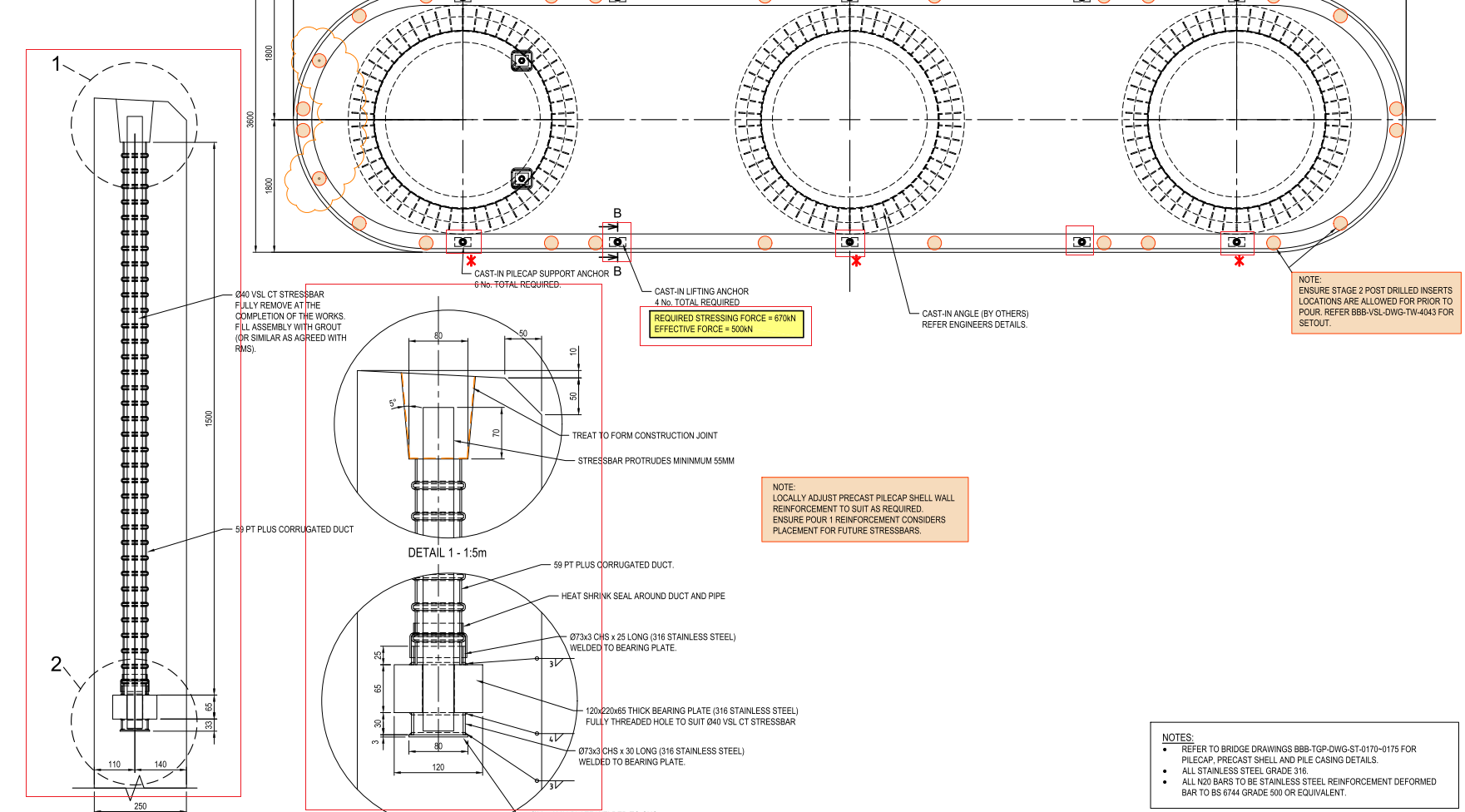
Temp PT drawings (above)
Revit Model
Tony Guy Partners (the permanent bridge designer) have added QR codes to their drawings with web links which allow anyone to download the revit model for that drawing from Autodesk myhub. No Autodesk software licenses are required and it allows 3d mark-ups, exploded views and sections/cuts to be viewed. These have been a real lifesaver for the engineers working on the rebar schedules/ITPs.
If you want to view the model you can download it from this weblink: Pile Cap Shell Revit Model
Finding the ‘G’ spot – High Pressure Dilatometer
I’ve been recently managing ground investigation works at a car park that will become a temporary construction site for four large steel frame modules (Approx. 50x50m). The GI is for the temporary foundations which will support these modules. The cores that have been found on site so far have revealed Weald Clay Mudstone at the depth of the proposed foundations. Recently I observed the use of a pre-bored High Pressure Dilatometer (HPD) which I had not heard of before. I thought this might be useful to explain a bit further. It’s an unusual but accurate method of finding horizontal soil strain ‘ε’ and shear modulus (G) in-situ instead of laboratory triaxial tests. It’s used much more commonly in France and other parts of europe but I’ve been told it is increasingly being used in the UK. It was developed from the Ménard pressuremeter, which is still used but is less accurate. It can only really be used in fine grain soils and most rocks, though problems are encountered in limestone where there’s lots of flint. The device isn’t useful in coarse grain material due to the low plasticity of the soil giving inaccurate results. It works by placing a cylinder at a certain depth with a membrane surround (see image below). The membrane inflates to apply pressure against the soil, where a number of sensor probes measure the pressure of the soil. This pressure is plotted onto a graph against the length of membrane expansion.

It comes in 3 different types:
- Self-Boring – Has the advantage of being more accurate as the dilatometer fits the hole much better and there is less disturbance of the soil, providing more accurate results. Not viable where there are layers of coarse grained material that can disturb the borehole or where rock is encountered.
- Push type – Similar to self-bored, but the sensor is driven into the ground. Has similar advantages but is limited to soft fine grained material such as clays. This can raise the stress of the surrounding soil, limiting the data you can get from this method. It is however much quicker.
- Pre-bored – A borehole is made to the appropriate depth and a dilatometer inserted into the pre-formed hole. The main advantage of this is that it is more versatile and can be used in a number of different type of soils. Best used in rock and stiff clays. Cores can also be taken during boring enabling lab testing of samples. Less accurate due to soil disturbance during boring.
A graph of average readings from the car park soil can be seen below showing cavity pressure against cavity strain. You will notice that there are a number of loops on the graph not too dissimilar to the stress/strain curve. The HPD operator expands the membrane until the pressure begins to level, and then releases some of the pressure, allowing for the soil to recover. The pressure is then reapplied causing an ‘elastic rebound’. This is usually done three times to give a spread of results. As I understand it is the average rate of this elastic rebound that can be interpreted to find ‘G’. The test is continued up to a point where the pressure begins to level off. It is not so easy to see in this image, but the individual sensor results show a gradual levelling off. I was told by the operator that they usually stop the test at this point as there is a risk of membrane rupture. As each of these cost about £80k this is understandable!

I have been told there are relatively few GI specialists in the UK who can carry out this kind of test and even fewer who are certified to interpret the results. That said it seems this is a much more accurate way of finding undrained soil properties from in-situ testing against more empirical methods such as soil classification properties against previous data. It may be particularly useful on sites where there is little empirical evidence. It is also more accurate than triaxial testing as the soil is not disturbed significantly. The HPD is likely useful for projects where a high degree of accuracy is required from the GI to build substantial foundations reducing the risk associated with the ground. This said I think that the HPD might not have been required on the this site as the foundations are temporary: a less costly triaxial test may have sufficed. I would be interested to know what other opinions might be.
Other information on soil properties can also be derived from these results such as the coefficient of uniformity (Cu), though for brevity this is not included above. Further reading can be found in Craig’s Soil Mechanics 8th Ed p240-8
Practical Lessons from Cofferdams
Note: Pictures are included at the end of this post.
Background
As part of the bridge sub-structure package, my team has been responsible for the construction of two cofferdams on the foreshores of the Clyde River to construct the pile caps. I was responsible for the planning of the cofferdam works. Unfortunately, I was off-site when some of the works were executed but have been involved in resolving a number of the issues outlined in this blog.
The northern foreshore cofferdam is located at bridge pier 1 and the southern cofferdam at bridge pier 5. The Clyde River is tidal at Batemans Bay with tides typically varying between +0.900m AHD (Australian Height Datum) to -0.500m AHD. The Geotechnical Design Report concludes that the groundwater is assumed to be hydraulically connected to the Clyde River.
The cofferdams are slightly irregular in shape (trapezoidal) due to a HV cable running within 300mm of the cofferdam wall at Pier 5. The same design was adopted for both cofferdams to reduce design costs and the works planned sequentially to reduce fabrication costs by re-using one set of waler beams. Later a decision was made to accelerate the construction programme which required a second set of walers and concurrent construction adopted.
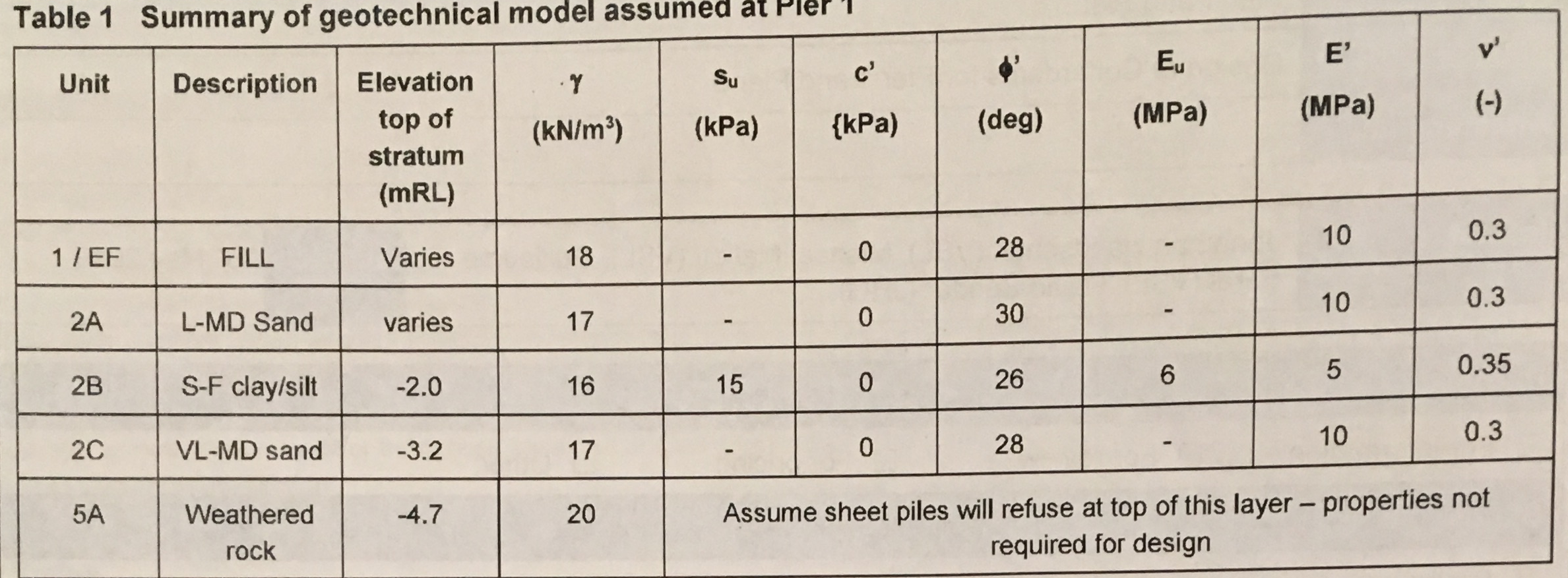
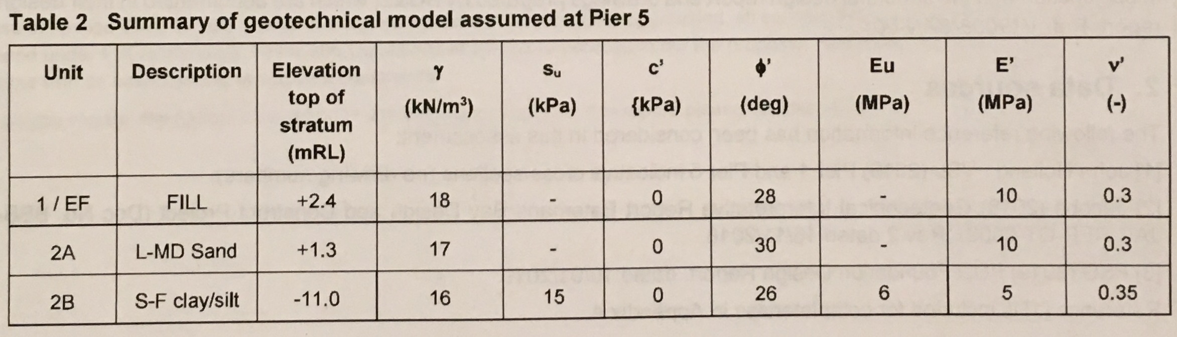
Ground investigation boreholes indicated a varying rock profile with bedrock occurring at approximately RL -5.000m AHD at Pier 1 but in excess of RL -30.00m AHD at Pier 5. The geotechnical design models for the cofferdams at Pier 1 and 5 are shown in the tables below. It was anticipated that cut-off could be achieved at Pier 1 but not at Pier 5 due to the rock-head depth.
Pier 1 Cofferdam
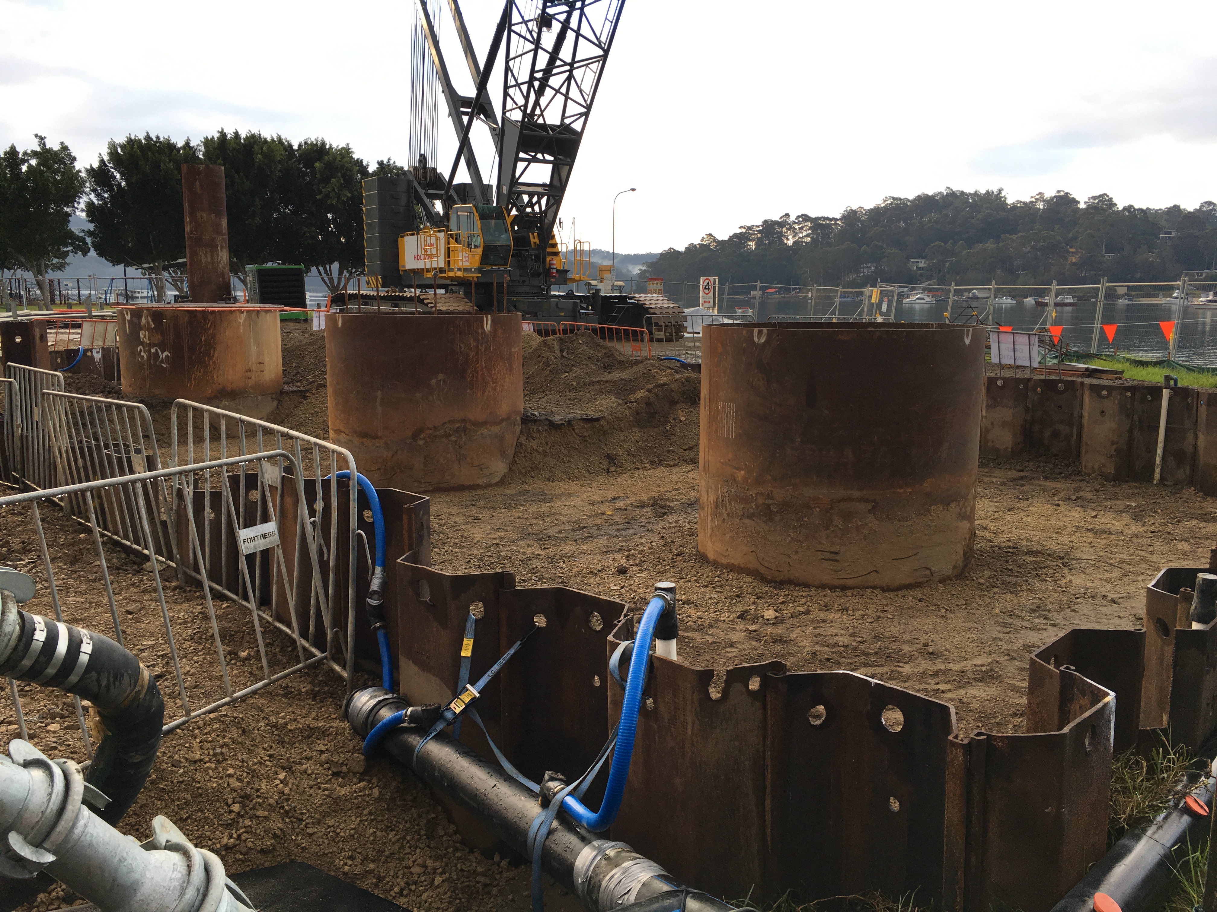
The northern cofferdam is located within the tidal zone. At low-tide, all sheet piles are above the waterline but at high-tide the majority of the cofferdam sheet piles are within the river.
The cofferdam was constructed at Pier 1 in two stages. The first stage was to drive the sheet piles on 3 sides of the cofferdam to create cantilevered retaining walls for the construction of a TW platform for a piling rig. The rig installed 3 No. permanent bridge piles (1.8m diameter bored piles) before the cofferdam was closed. When the cofferdam was complete all sheet piles hammer-driven 200-400mm into the rock-head.
GU18N piles were procured and cut down on-site to reduce the number of piles required. The minimum design embedment was RL -5.000m AHD. The external ground level on the land-side was is RL +1.700m AHD with a final excavation depth of RL -1.200m AHD before 150mm of drainage rock and a 50mm blinding layer was placed.
Delta-13 corner connectors were used to increase water-tightness however the connector at the final corner could not be installed correctly due to differences between the design and as-built alignments.
Pier 5 Cofferdam
Due to program sequencing and existing access for the piling rig, the 3 No. permanent bridge piles were installed prior to the cofferdam construction.
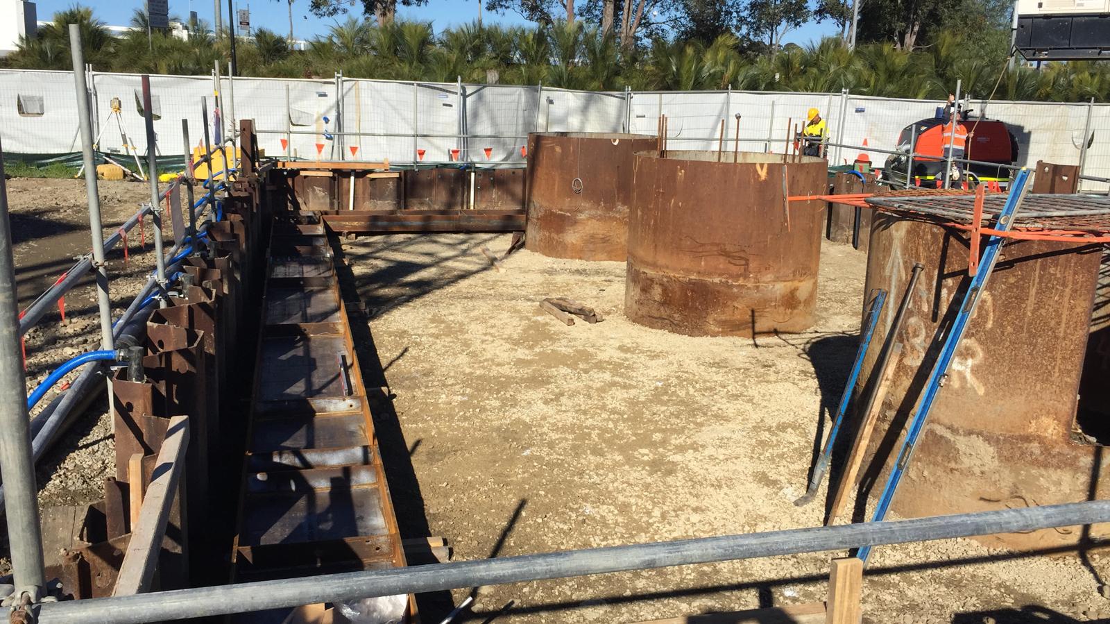
The Pier 5 cofferdam is located approximately 15m from the edge of the river bank. 12.0m SPU-IIIw piles were driven under vibration to a minimum toe embedment of RL -9.600m AHD. The surrounding ground level is a TW platform at RL +2.000m AHD and a final excavation depth of RL -1.850m AHD was achieved (based on the on-site Geotechnical Engineer’s direction) before 300mm of drainage rock and a 50mm blinding layer was placed.
Again delta-13 corner connectors were used to increase water-tightness however the final connector could not be installed variation from the design and as-built alignments.
Problems:
- Budget. The cost of the cofferdams was overlooked during the tender, therefore, the cofferdam works had no budget. All decisions have been made on this basis with no appetite for additional expenditure to mitigate potential risks that may not materialise. Observation: Remember to include the cost of TW in tender submissions.
- Confined space requirements. When is a cofferdam a confined space? It seems everyone has an opinion and no two are the same! On the southern foreshore there are mangrove swamps which creates the potential for the soil to contain pockets of hydrogen sulfide gas (H2S) due to the decomposition of the organic material. High concentrations of H2S gas have been found at other project sites on the south of the river. A lot of my time planning the execution of the cofferdams was spent managing the potential confined space risks that could occur in the cofferdam due to H2S gas and plant or welding fumes. The risks to workers were reduced by providing ventilation fans to circulate air and using gas detectors to monitor the atmospheric (oxygen, carbon dioxide, hydrogen sulfide and explosive gas levels) to ensure levels remain within acceptable limits. As part of this process every shift I conduct a confined space assessment to determine if the cofferdams should be classified as a confined space. Observation: The risk of contaminated ground was covered in the teaching prior to Ex COFFERDAM but I don’t recall discussing confined space risks. Would this risk be worth highlighting to future PET courses?
- Lack of knowledge. There is a lack of knowledge about cofferdams amongst the site engineers. I found that I had more knowledge than most based on Ex COFFERDAM. One Senior Project Engineer initially designed the cofferdam (before an external geotechnical consultant was employed to verify the design). He has admitted that it was the first time he had designed one and would do things differently if he was to design another cofferdam. A John Holland supervisor has constructed cofferdams previously on other projects. Observation: You might actually know more than you think after Phase 1.
- Personalities. I have found the personalities of the site supervisors key in the standard of works they achieve. One supervisor is optimistic, under-resourced and over promises – consequently, he routinely fails to deliver. Another supervisor is well-organised and has invested time in building his team – they routinely deliver works to a high standard. Observation: It has been interesting to observe the same design delivered by the different teams and observe how their work ethos has affected the problems faced on site.
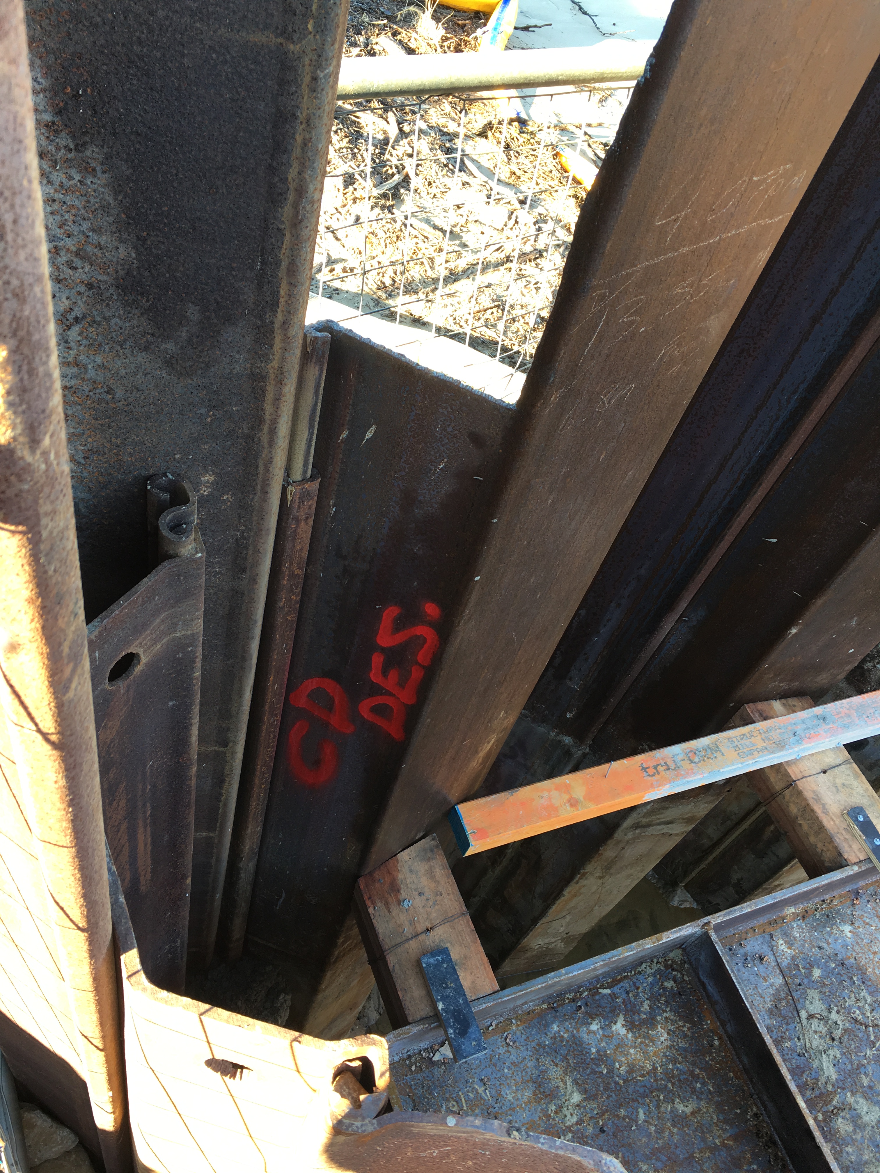
- Pile procurement. To reduce the cofferdam costs surplus/second-hand sheet piles and connectors were purchased from other construction sites. Essentially you get what you pay for – the poor quality second hand piles have caused a number of issues on site (increased labour costs, slower installation rates and clutch leaks). Observation: Trying to save money upfront has cost significantly more in the long run.
- Clutch Leaks. To save money, no clutch sealant was used prior to driving the sheet piles. The view from the optimistic supervisor was that the cofferdams would be fairly watertight and any leaks could be sealed post-excavation via calking rope or welding. At Pier 5 the wall leaks have been relatively minor except for at the corner where the delta-13 connector could not be installed. This resulted in a surface sinkhole as the groundwater caused fines to migrate into the cofferdam. This was sealed by blocking the gap and using stabilised sand to prevent further fines migration. At Pier 1, every clutch leaks…badly. Due to other work priorities, and needing to work at low tide slow progress is being made on welding the clutches. Observation: This is a big issue for permanent work construction as the groundwater will contaminate the rebar and prevent concreting works. Options for sealing a cofferdam after sheet pile installation are very limited – it is advisable to use clutch sealant before driving the piles as the other methods as it is too late when you start excavating.
- Boiling/Piping? At Pier 1 due to the rock-head and reduced toe embedment, there appear to be issues with a high hydraulic gradient boiling at the base of the excavation in the middle of the river sidewall even at low tide. I’m not sure if this would be classified as boiling/piping but you can see for yourself in the video below. This increases the groundwater flow into the cofferdam with 100mm routinely made overnight and up to 500mm over a weekend. In contrast, the increased embedment depth at Pier 5 appears to have minimised the issues with groundwater penetration due to the increased hydraulic flow path around the sheet pile and the increased soil plug weight inside the cofferdam. Of note, the drawings state ‘water tightness of temporary structure not designed. If waterproofing is required, to be designed and documented by others.’ Observation: I have not found any assessment of the hydraulic gradient or flow net for the cofferdam. This appears to have been largely ignored during the design stage. I have measured the recharge rate of the Pier 1 cofferdam but have been unable to assess this further due to other workloads.
- Groundwater. The lack of geotechnical knowledge and understanding of groundwater is worrying. A spear dewatering system was installed at Pier 5 but there was significant disagreement of when it should be turned on and off. The system was removed following the blinding layer installation as the system was extracting 0.5l/sec which the SPE felt could be managed via sumps. This is achievable during working hours however site environmental restrictions prevent dewatering out of hours which has resulted in a flooded cofferdam in the mornings and at weekends following high tides. The ability of the spear system to depress the groundwater level below that of the sump is not understood nor is the importance of running the dewatering system over a protracted timeframe to depress the groundwater levels. Interestingly I have just been instructed to organise the installation of a spear dewatering system in the Pier 1 cofferdam to reduce the water entering the cofferdam. I believe this is the only option we have to control water ingress below the blinding layer as the clutches are not sealed. Observation: The rush to demobilise ‘unnecessary’ dewatering equipment is causing challenges with the permanent works (reinforcement and concreting works) which need to be kept out of the groundwater.
- Alignment. There were significant issues with maintaining the design alignment when driving the sheets as no driving frame was used (sheets were driven individually). As fixed walers were fabricated the 300mm+ variation was significantly more than could be accounted for with metal packing shims. A Temporary Works Modification Request was approved which replaced the fixed waler support brackets and metal shims with restraint chains and hardwood packing. At pier 1 the location of HV cables within 300mm of the wall required non-destructive testing to expose the cables so the asset owner could observe the cables as the sheets were driven. This required formal notifications, additional Safe Working Method Statements and made installing and aligning the wall more challenging due to the open trench. Observation: Adjustable proprietary strut/prop systems can be adjusted more easily to compensate for installation inaccuracy. If using fabricated (fixed) props I recommend assembling the walers first in situ and using them as a driving frame to minimise alignment variations. Proprietary waler restraint chains were far easier to install than the fixed bracket design.
- Quality Issues. The works were due to be self-performed by John Holland (JH) employed labour to reduce costs. A JH crew started the sheet pile installation at both cofferdams but later handed it over to a sub-contractor (the Temporary Boat Ramp failure [see previous blog] disrupted the permanent piling contractor’s works so they were employed on day rates to perform additional works to minimise demobilisation costs). The cofferdams have subsequently been handed between JH crews. With the works starting behind programme the focus has been on time at the expense of quality. Pier 1 sits on the project critical path. The blinding pour was rushed and started too late in the afternoon to be completed within the site working hours. This resulting in inconsistent blinding levels above the RL and critical trench reinforcement (to support the pier formwork) being installed in the wrong position (horizontally and vertically). Critical sections of the blinding including the trench reinforcement have been ripped out and replaced loosing over 4 days of productivity at Pier 1. Observations: The lack of crew ownership combined with a desire to recover the programme and a vague ITP has resulted in the delivery of low quality work. This is most noticeable at Pier 1. The Pier 1 blinding pour should have been delayed. The engineer managing the blinding pour was pressured into making mistakes.
- Wall Monitoring. Part of the designer’s requirement was to monitor wall movement at 16 locations around the cofferdam (2 positions on each wall at waler height and 2 positions on each wall 0.5m above the base excavation level). Set deflection limits were agreed including 80% trigger levels to increase monitoring requirements. This was a great idea in principle but was practically impossible to achieve on-site due to physical site and line of sight constraints. This was discussed with the designer and a practical proposal developed on site. The wall monitoring was to be conducted daily until the wall movements stabilised. The monitoring identified that the Pier 1 land-side wall one wall moved 17mm (greater than the 80% threshold limit) over a weekend. This triggered significant consultation with the geotechnical engineers and structural designers to determine a solution. The wall movement was attributed to a surcharge load from an excavator (which was permitted in the design). As the deflection remained less than those permitted in the cantilevered state new deflection thresholds were agreed with the designers. The wall movements have no re-stabilised and are monitored bi-weekly by the site surveyor. Observation: The set wall monitoring procedure developed with the site surveyor was essential to detect the wall movement. Simple solutions developed in an office may not be practical on-site. The designers were receptive to adjusting the monitoring plan based on-site practicalities.
Any guidance or ideas of how to seal the cofferdam clutch leaks would be very welcome!

The state some of the second-hand piles arrived in…
Pier 1 cofferdam as cantilevered retaining walls for the piling platform
Pier 1 cofferdam showing proximity to river at low tide. Piles on LHS are shorter to reduce the number of piles and prevent tides from entering cofferdam around the side during construction.
Pier 5 cofferdam at stage 1 dig (prior to waler install). The foreground shows the dewatering spear system and header main.
Pier 5 cofferdam waler installation.
Pier 1 delta-13 connector not closing on sheet pile clutch due to misalignment
The lack of delta-13 connector at the Pier 5 resulted in visible groundwater flow

The groundwater flow washed fines through the gap resulting in a sinkhole outside of the cofferdam.
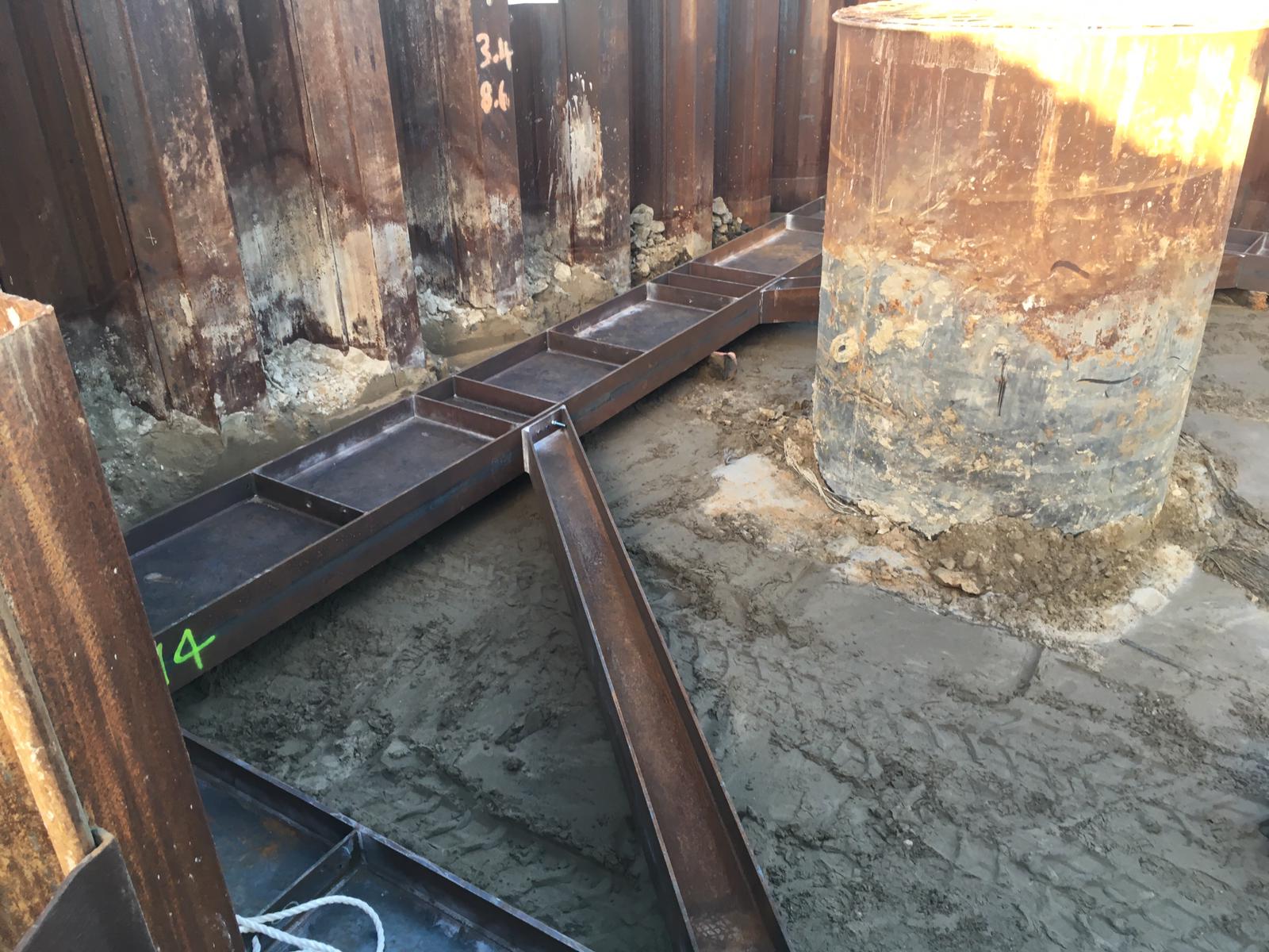
Installation of walers at Pier 1 cofferdam (level appears lower due to removed piling rig platform removal and reduced toe depth.
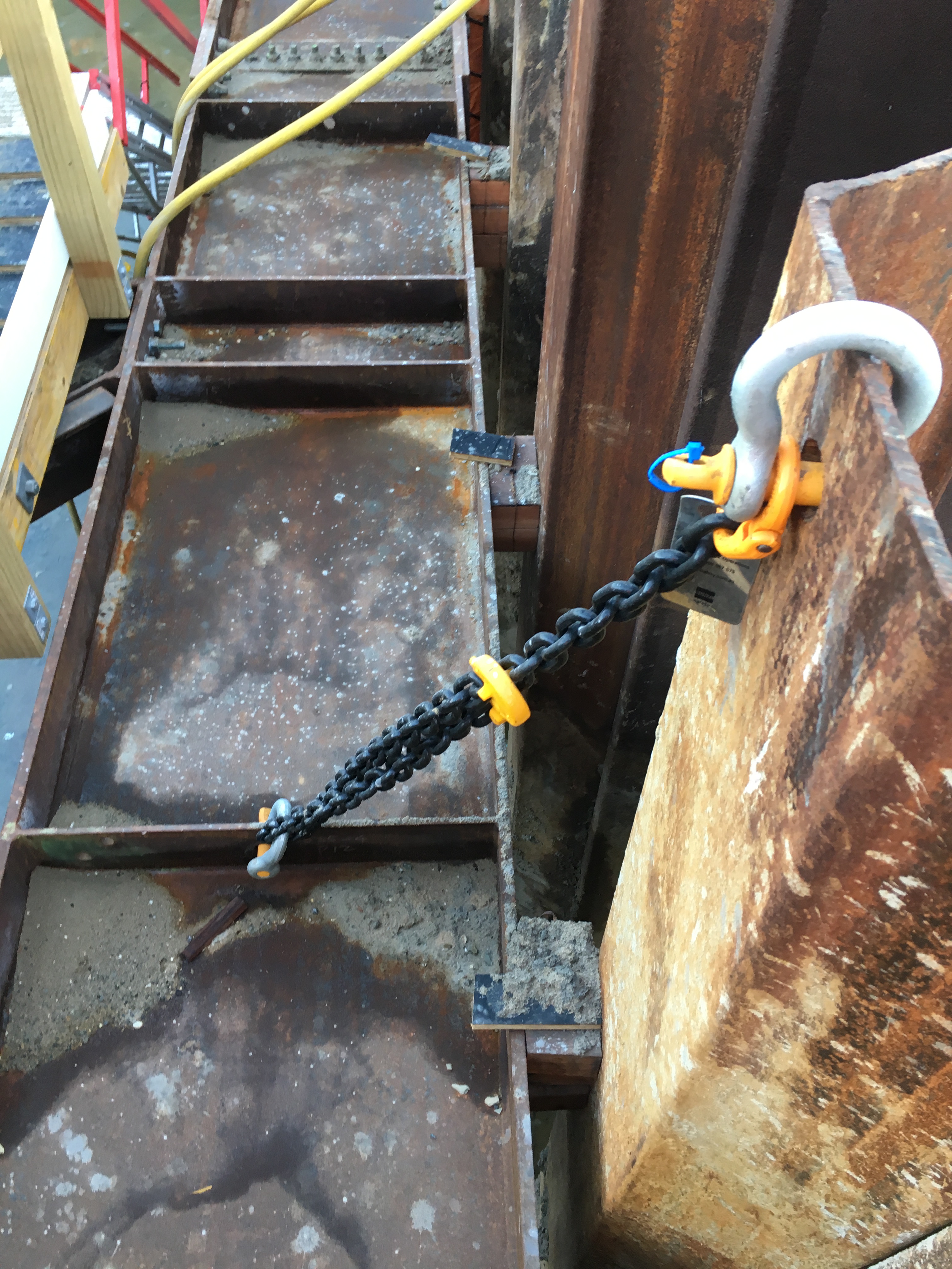
The waler restraint chains were used to solve the issue of a lack of sheet pile above the waler at Pier 5. The chains were easier to install than the fixed brackets. Note the timber packing that was initially due to be 1-10mm steel plate.
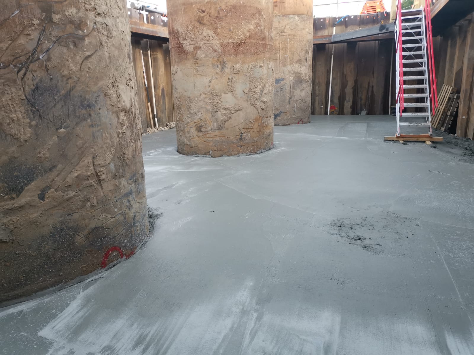
Blinding layer complete at Pier 5
Meanwhile high hydraulic gradient at Pier 1. Possible piping/boiling? The sand is being forced into the cofferdam from the river bank/beach outside the cofferdam.
Pier 1 water penetration through the clutches due to tide.
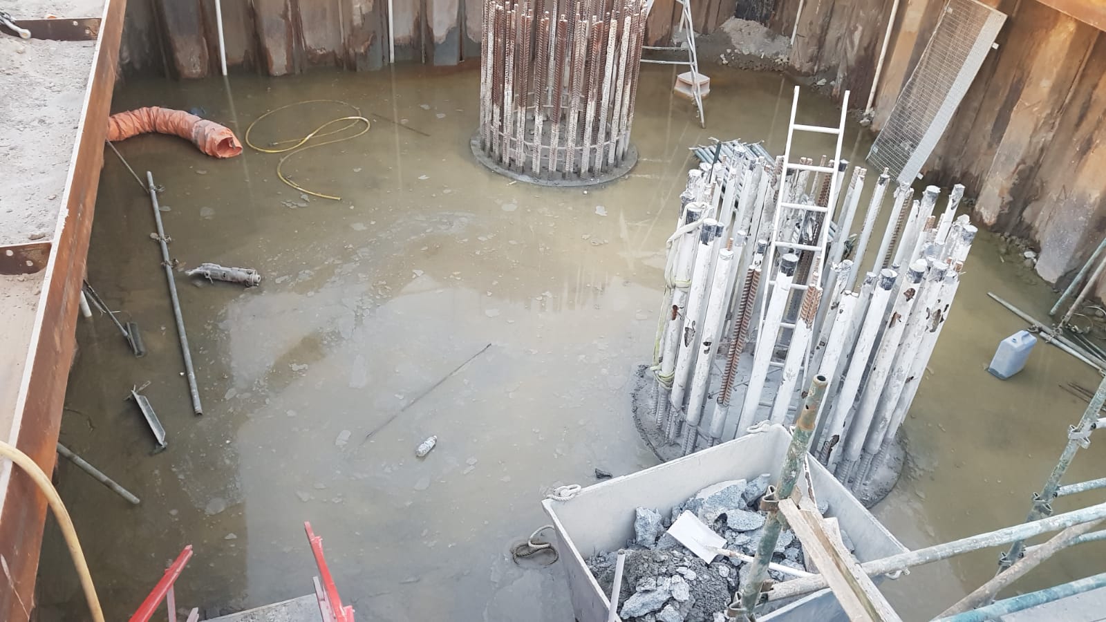
Flooding at Pier 5 due to groundwater. Usually <50mm.
Flooding at Pier 1 cofferdam. My usual morning view of 80 – 100mm above blinding layer.
Pier 1 following a high tide
Pier 1 record water level of 500mm above blinding following a weekend with high tides.

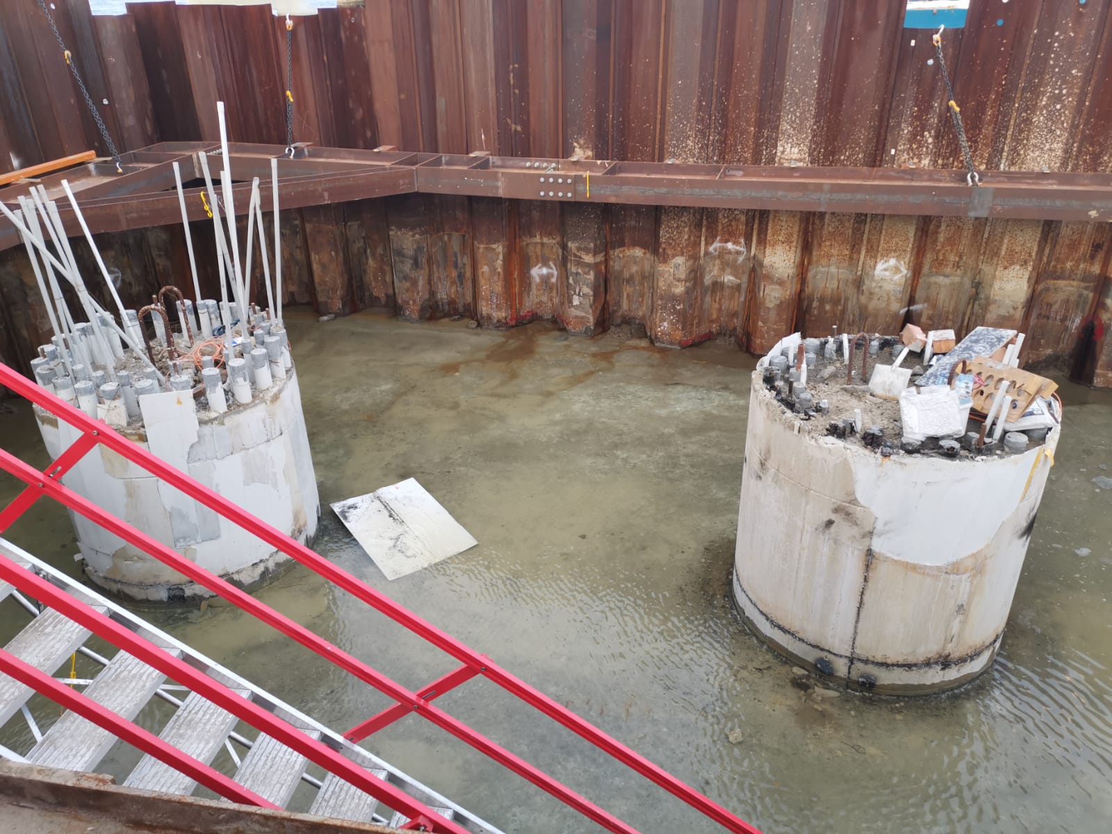
Pier 5 pile overpour break back complete. Cleaning rebar for insitu pile cap. Groundwater managed by sump pump (back right corner).
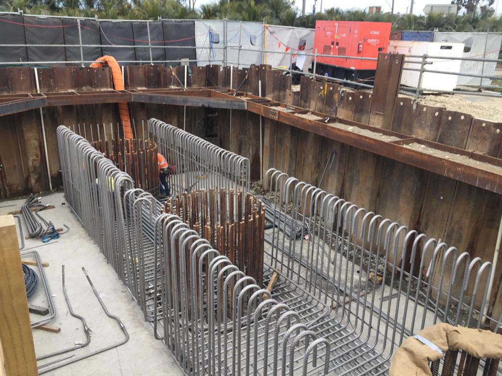
Current works at Pier 5. In situ steel fixing.

Current works at Pier 1. Breaking out blinding and reinforcement.

New blinding in the excavated trench was laid at Pier 1 today.
Plate bearing test
Victoria Square Woking are currently in the process of removing the existing shallow foundations of an old car park so they can construct CFA piled foundations for the new car park.
The demolition contractor are obligated to leave site with 1) the guarantee there is no existing structure in the ground and 2) the ground is of sufficient strength to support the piling (create a piling mat)
Yesterday on site the demolition subcontractor brought a plate bearing test team onto site to ensure the sub grade was of a high enough capacity before continuing up. An intermediary test. I thought I would share the test in case any of you were interested.
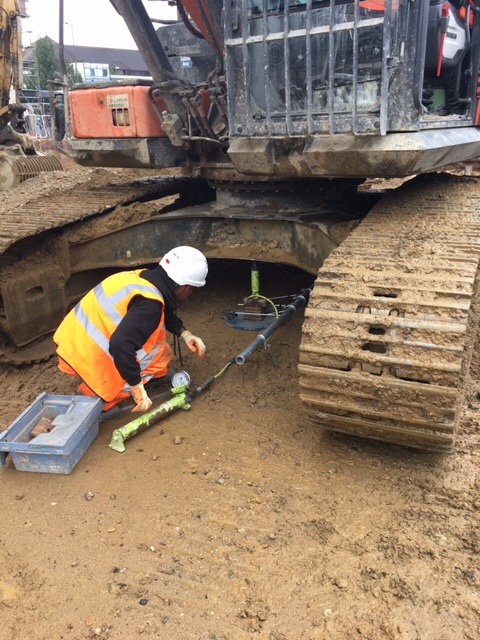

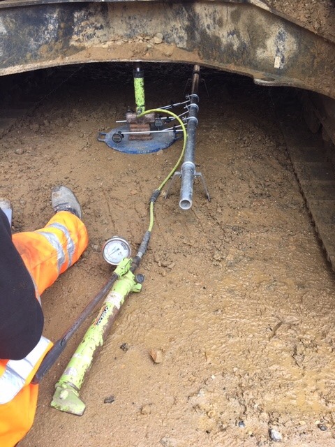
Effectively what is happening is a plate is placed under one of the excavator machines and a hydraulic jack is connected to the two. When the jack is lifted a gauge informs the operator what pressure the plate is under.
A scaffold tube is placed next to the plate with three strain gauges fixed to the plate. The differential movement between the scaffold tube and the plate offer an immediate settlement value for the plate. Once you’ve got both pressure and immediate settlement calculations can be performed to give a CBR %.
I am still awaiting the report back but the guy on site said we achieved 25% which is good considering our specification was to hit 5%
Point-cloud Data Capture for Tolerance Analysis of ‘As-built’ Structures within the HPC Nuclear Programme
The Main Civil Works (MCW) contract in place for Hinkley Point C (HPC) has seen a vast amount of concrete being poured, using vast amounts of rebar. Most rebar used on site was due to be at least 43mm in diameter but in response to lessons learnt in the Fukushima nuclear accident, the design has been strengthened in many places and now contains ‘double tied’ rebar – at least 86mm across. HPC’s civil structure concrete will also contain thousands of embedded items such as plates (90,000 of!), mounting bolts and ‘Halfen’ rails on which the many E&M systems, structures and components (SSCs) will be placed.
Due to the rebar situation, the MCWs are working off around +/- 80mm tolerances for their embedded items. The E&M execution designers and installation contractors are working off +/- 2mm. Anyone see an issue here?
The simple solution is to assess where tolerances are out of spec, and present this information to the E&M SSC execution designers to mitigate (design-out) the risk. To this end, accurate 3D positional data is required for the thousands of MEH related support items embedded within the MCW structures.
This issue is a long way towards being resolved through the application of 3D point-cloud data-sets which can be analysed using an innovative new software platform called…


The ‘as-built’ civil structure point-cloud is fed into the software tool alongside the design data for the structure and each embedded item. The software then provides a 3D ‘trueview’ of the structure and will indicate where embedded items are IN or OUT of tolerance using a traffic light system as can be seen in Fig 1. Each component can then be analysed to check its actual position (x,y,z, coordinates). The fact that almost all plates are out of tolerance on the left wall would suggest the wall is probably in the wrong place!
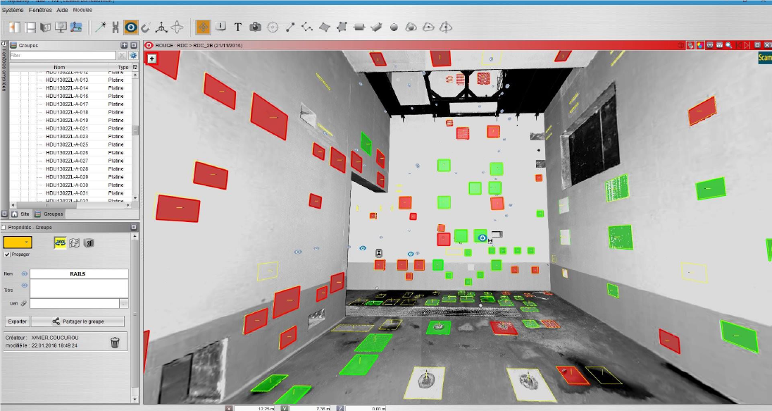
Fig 1. Tolerance analysis of embedded plates within a concrete structure using “My-Survey DAC” by Quadrica
Fig 2. then shows how a deep dive analysis can be carried out for each specific embedded item with clear reference as to where the design coordinates ‘should’ be and where the actual as-built condition has found them to be in reference to the tolerance parameters.
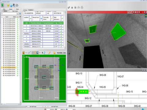
Fig 2. In depth analysis of a specific embedded plate to show design coordinates, actual ‘as-built’ coordinates and deviation from defined tolerances.
It is also possible to perform CAD model component overlays onto the ‘as-built’ structure as shown in Fig 3. to conduct interface control and to assess the impact of out of tolerance walls, openings, doorways and/or embedded items.
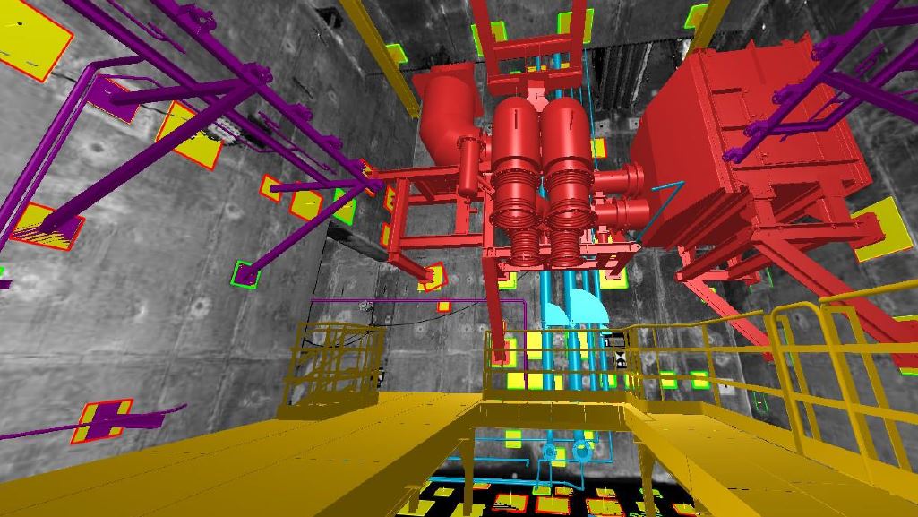
Fig 3. CAD model overlay on to ‘as-built structure’
In developing this methodology, a number of potential benefits have been identified:
- Access to ‘as-built’ data much earlier
- Single point data acquisition, analysis and use. No requirement for SSC installation contractors to conduct their own scans to understand the ‘as-built’ condition
- Early identification of potential problem areas
- De-risk support design and allows for fabrication at source
- Additional cross-project as-built benefits (Lifetime Quality records and Building Information Modelling)
As such a financial saving of £40-60m is predicted throughout the HPC construction from contingency funds associated with risk mitigation.
As well as structural tolerance analysis there are also a number of other applications such as:
- BIM modelling
- 3D CAD/mesh model generation
- Production of isometric drawings
- Volume surveys (earthworks)
- Clash detection
- Final ‘as-built’ survey
- Deformation surveys
- Reverse engineering
- Orthophoto or “Trueview” 3D imagery
- Virtual/augmented reality
- Walk/fly through orientations
Having had to conduct a lot of research before going firm on the “My-Survey” software platform it was surprising how many different software platforms are available on the market now for use in point cloud applications (see Fig 4).

Fig 4. Various point-cloud analysis software platforms
I’d be interested to hear if anyone else is familiar with any and if there are any innovative applications as to how they are being used (turns out I’m writing a thesis on it all?!)?
Steel Fibre Lightweight Reinforced Concrete
First patented in 1874 and used extensively for bomb damage repair to airfields in WW2, SFRC is a well established construction material with a number of potential benefits, especially when used in situ to form composite slabs on profiled steel decking.
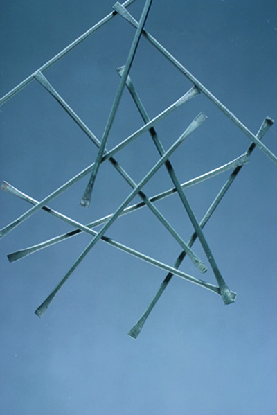
Steel fibres are graded I – V according to BS EN 14889-1
Steel fibres are often used to replace the steel mesh or fabric reinforcement in slabs. As well as composite slabs, they are used extensively in ground bearing slabs and pile-supported floors and can replace much, if not all, of the traditional welded reinforcement.
By mixing steel fibres into ready mix concrete at the batching plant you can avoid the need to pre-place traditional reinforcement. This gives considerable time and H&S benefits (manual handling, cutting, etc) as well as some secondary benefits such as reduced numbers of deliveries to site and less demand on crane time to lift bars and mesh into place. You are also able to better guarantee distribution of reinforcement through the depth of the slab, removing the risk of misplacing reinforcement within the depth of the slab.
On constrained sites (like mine) hook time is at a premium and there is limited lay down space for material. In addition, the build sequence only allows us to pour slabs once the two floors above have been steel decked to provide some measure of overhead protection (i.e. we cannot pour concrete on L01 until L03 has been completely decked by the steel erectors). On the other hand, once L02 and L03 are fully decked we have no way of craning our bars and mesh onto L01 as the lay downs will have been covered over. As a result the concrete contractor has to design, call-off , deliver and bulk lift all reinforcement for L01 eight weeks before he is able to access the level to place the reinforcement, run out pump lines and pour the concrete.
It seems to me that a large amount of this work could be rationalised through the use of SFRC in the concrete mix so I am wondering why it hasn’t been specified on this project. One issue could be that in order to provide a resisting stress under tension you need strain in the steel – in traditional (in plane) reinforcement the strain required is very low but in randomly oriented fibres there could be greater strain before the required stress is realised, resulting in higher deflections. Compression performance should be unaffected.
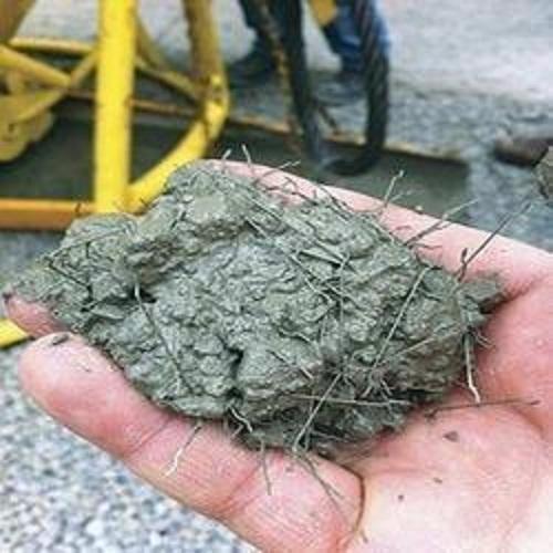
Steel fibres in a handful of the grey stuff
This project has 11 different composite slab combinations but the ‘generic’ case is a LC30/33 (Lytag) concrete on a profile sheet deck. The reinforcement is a H12 bar in every sheet trough (for fire resistance) and either A193 or A393 mesh in the top. Where this mesh is for crack prevention only I can’t (yet?) see why it couldn’t be replaced by fibres. The larger mesh is specified where the slab is designed to transfer diaphragm loads through the structure so there is more to be looked into there. I don’t propose replacing the fire bars.
Anyway, this is very much a new thought which may not go anywhere but I would welcome people’s thoughts or feedback from anyone who has seen this in action.
Oh, and do we still use it for airfield damage repair? I don’t remember using it.
The good ideas club
The Woking parking complex has now been demolished to ground level and the strip out of the ground floor slab and foundations has begun.
The current foundations are large shallow strip foundations at approximately 7m in width, 1.5m depth and 70m in length. They are heavily reinforced and approximately 1.5m below the ground force slab.
The structural designer has planned for the entire removal of the foundations to make way for the piles and pile caps that will be replacing them. However, ever the opportunist our demolition subcontract has had the idea to only remove the sections of the strips that would collide with the new pile caps to save time, money and waste. His argument also that the hole in the foundation would save time on having to build and strike formwork.
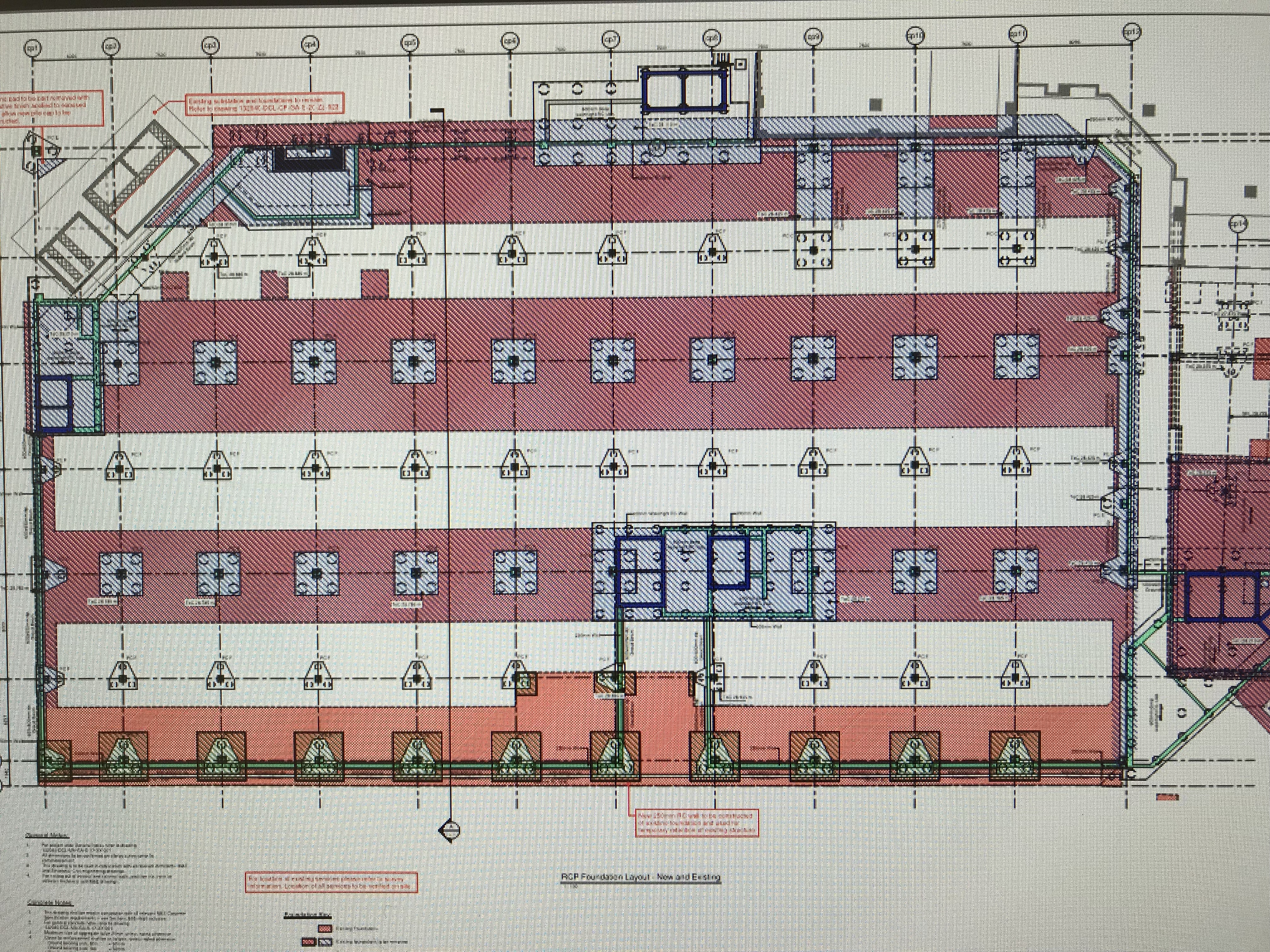
The drawing above shows in pink the existing foundations with the proposed. It sounds perfect on paper, but the question remained would it really be easier to precision cut out sections of a foundation at depth rather than dig the entire lot up.
The first challenge was the depth. The batter needed to get down to that depth is around 1.5m. The centre point of the proposed pile caps are 7m c/c and the caps themselves are 3m wide. If you excavate this cap with the batter that does not actually save you much in terms of excavated fill. It also means your site is 2/3 hole and 1/3 trackable access.
Secondly was the rebar. Bulk removal with a leading edge would simply mean using a muncher to rip up the rebar. However the process of leaving holes in the foundations requires a breaker machine followed by a bloke hot cutting the rebar instead. A trial foundation was dug on site this week and the whole process took 2 days for one pile cap. 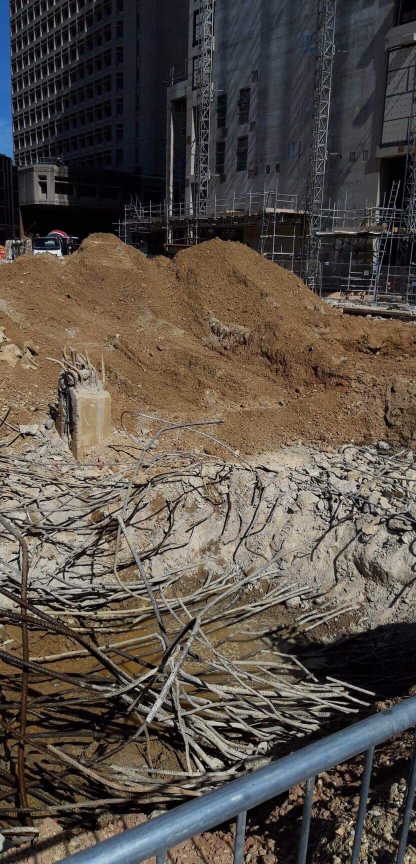
the photo above is the trial attempt to “neatly form a hole in the existing foundation”.
In my eyes value engineering has its place and innovation should be considered, but there is a time and a place and I don’t think it worked this time. As the PC we were all sceptical but allowed the SC to trial it, they can chose whether they persist with this methodology but they will not receive an instruction from us to permit them any further allowances.
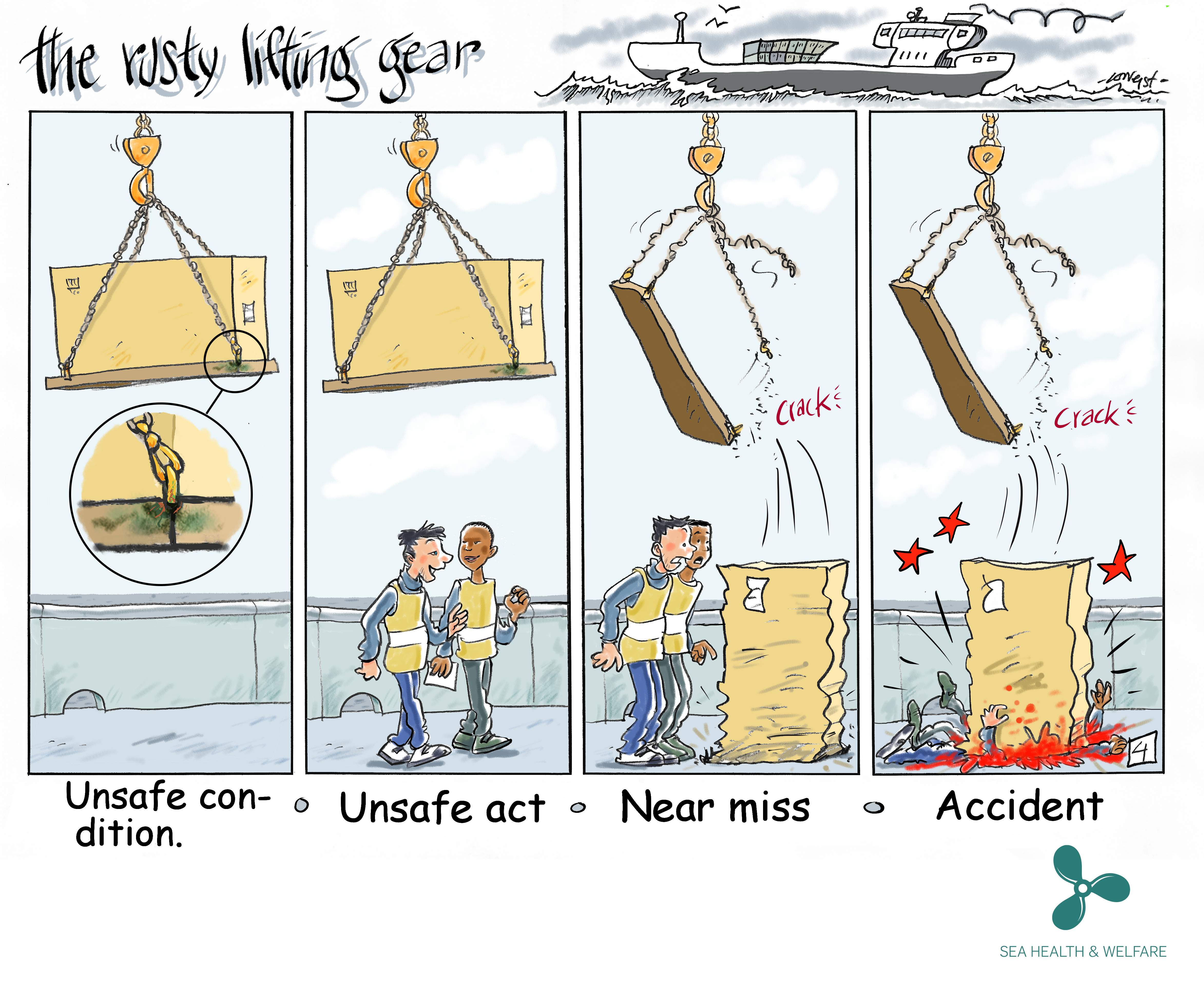
The importance of definitions
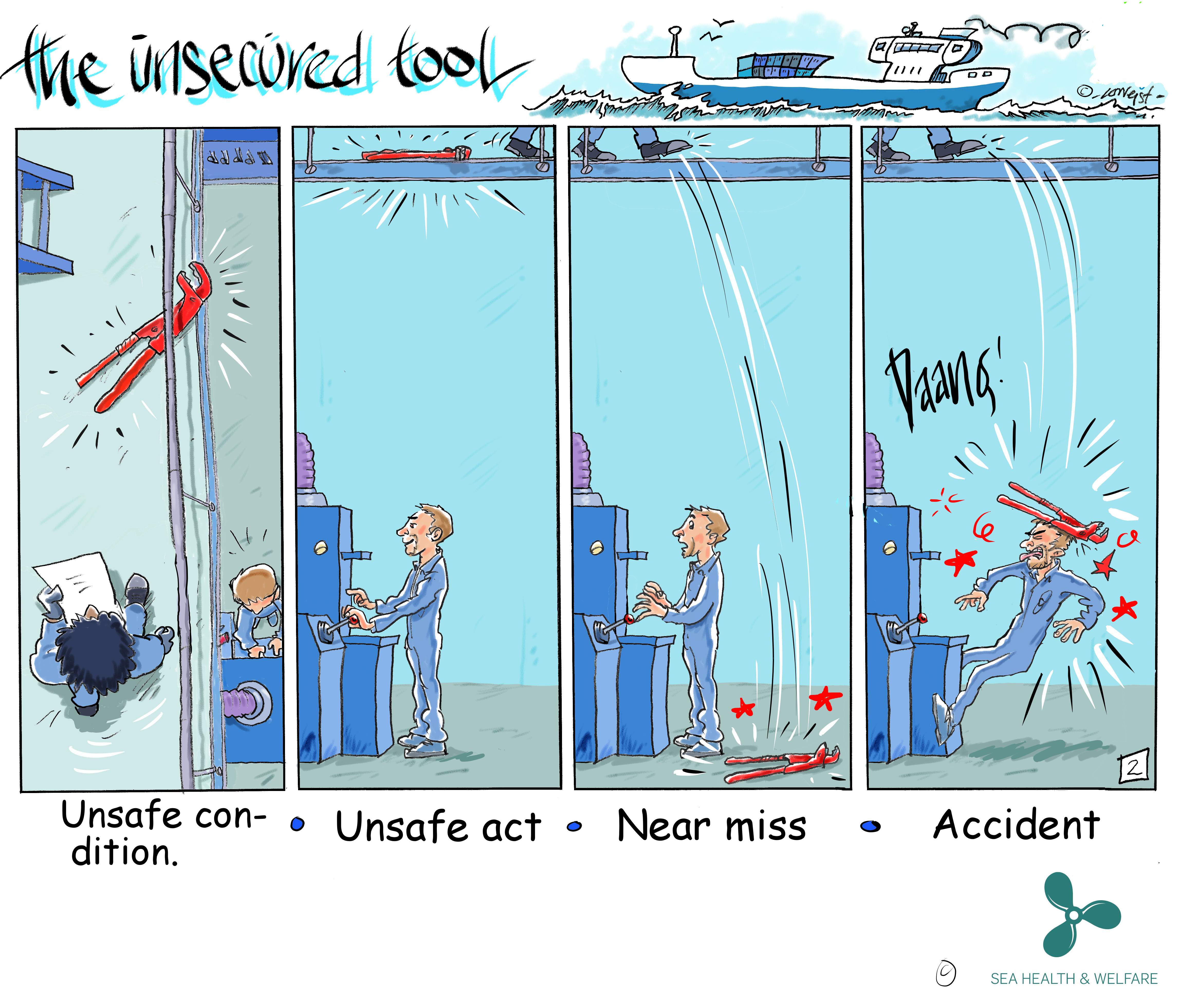
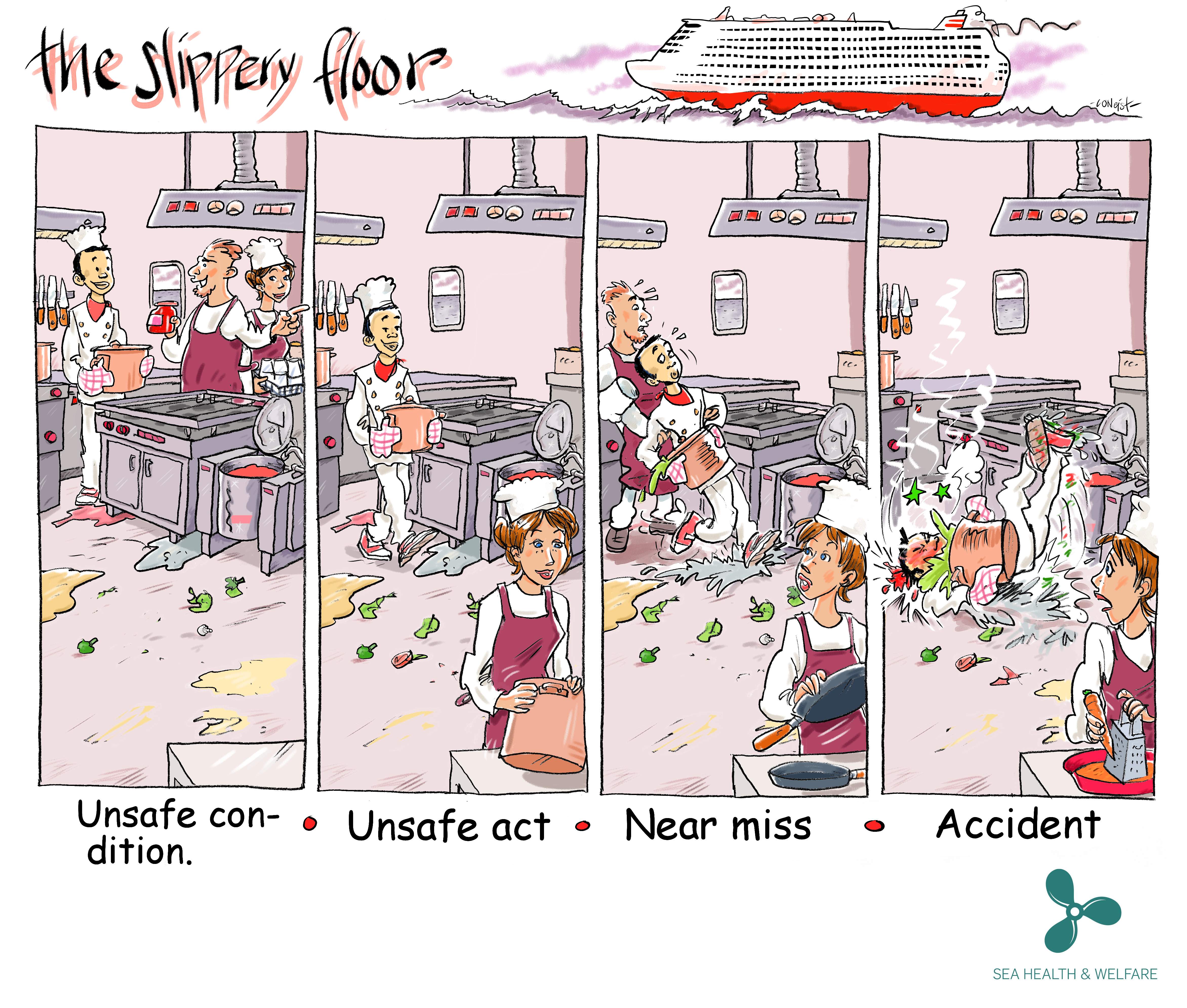
Following a few recent blogs regarding H&S incidents I thought I’d share these little cartoons we found depicting the different terminology for various incident types.
The first image seems particularly relevant for both Mark’s and Al’s recent experience with lifting equipment. From reading the blogs it sounds to me like Al’s site experienced and unsafe act when a worker was seen under an unsupported load. Mark experienced an unsafe condition (the poor slinging technique) which led to a near miss (the thing actually fell but no one was hurt).
While of course all of these incident types should be properly addressed, and all have degrees of severity within them, the terminology used can be quite important.
Take, for example, our ever-troublesome scaffolders who failed to properly enforce an exclusion zone on a public-access pavement beneath their work area. They were spotted and the situation was corrected but was this a near miss? Nothing was dropped onto the pavement and no one was injured but the potential was there. This was reported as an unsafe condition (working overhead without edge protection). Had it been labelled a near miss (with the potential to impact the public) we would have had a world of problems.
This may sound like opportunistic word play but it is an important delineation. From a safety point of view it was a very serious occurrence, and was treated as such by all involved, but contractually the wording is vital, similar I suppose to John Holland’s 1P rating in addition to the strict H&S term. The irony of the situation is they were up there erecting a scaffold fan to protect pedestrians from falling objects!
A great deal of fallout resulted of course (revisiting method statements, tool box talks, safety briefings, etc) but the point of this blog was the importance of definitions in contractual communication, and not just in H&S.
Precast pile de-heading
Hi all! I just thought I’d put up a quick post about a new technology/process I have been involved with this week.
Having almost completed the first stage of precast pile installation on my site, we are ready to start de-heading piles in preparation for pile cap construction.
Pile de-heading is recognised as a risky activity within the construction industry. Eventually, approximately 4500 precast concrete piles (13,500 individual pile segments when considering spliced piles) will be installed across the east zone of the West Gate Tunnel Project. Given the inherent risk of the deheading activity, a concerted effort has been undertaken to investigate the safest ways to undertake each stage of the process.
A lot of thought and consideration has gone into the different methods available to remove or reduce the people and plant interface, a High Risk Construction Work Activity under Victoria Worksafe (Vic State version of HSE), which are activities involving people working in close vicinity to items of plant.
De-heading or pile-trimming refers to the practice of cutting piles to a pre-determined level after they’ve been driven into the ground to the required depth or capacity, which is around 30 metres generally across the East Zone and 12m-14m across the scope of works conducted thus far on my area of responsibility.
Traditionally a number of methods have been used to perform the de-heading, including workers using hand-held ‘demo’ saws in combination with plant to support and remove cut sections. Typically, this activity involves a crane holding the pile, while workers saw cut the concrete and corner longitudinal reinforcement This involves a lot of people/plant interface and other safety risks such as: falling concrete segments, potential silica dust inhalation, injuries associated with repetitive tasks (such as ‘White Finger’ vibration injuries) and exposure to loud noises.
After investigations into safer options with the piling subcontractor ‘Keller’, it was decided a much safer method for these works was to use an excavator with a de-heading attachment.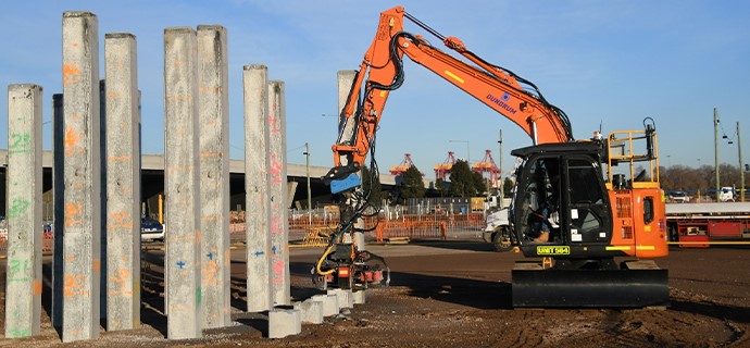 How does it work?
In simple terms, after the de-heading attachment is connected to an excavator arm, it connects to a pile and its blades cut through the reinforcing steel at each corner. Another excavator then moves in, grabs the pile and snaps it at the cut-off point and then carries the excess length of pile directly to the waste skip for removal. This technology is not entirely new and has been used before in Australia, but rarely, as it suits projects with a large-scale piling requirement, such as ours due to the increased costs.


The main benefits of using this pile-trimmer method include:
1. Safety: as this process is undertaken via an excavator, it completely removes the people/plant interface.
2. Environmental improvements: it’s quieter than other options, such as jackhammers, while dust dispersion is mitigated as the device ‘self-doses’ water during cutting.
3. Increased productivity: this method is quicker than other de-heading methods, meaning increased cost of plant/technology can be saved against traditional methods through saving in time and project schedule.
4. A better result: the end of the cut-off pile is ‘cleaner’ than it would be using other methods.
What’s next after the pile de-heading?
unfortunately, the plant trimming method cannot be used down to the final cut-off level of the pile. After the piles have been trimmed to the correct height (300mm above the surface), the next step is known as breaking-back the pile. It involves digging around the piles to the cut-off level, then chipping away the concrete to exposing the reo bars.
This is another process that will be performed mostly by excavator, with only minimal use of a jackhammer at the final stage, to expose the reinforcing steel. Again, reducing the risks to workers on site.
This method of pile de-heading is a big step forward for safety across the industry and will likely see increased use in the future, especially with Tier 1 Contractors.
