Archive
How to put overweight building design on a diet?
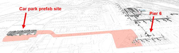
The largest project at Gatwick ongoing at the moment is the western extension to Pier 6 at the North Terminal. The project is currently at RIBA 3 (developed design) stage. In order to mitigate the impact to aircraft operations, the construction method involves building a steel structure from four separate modules off-site at a car park. It is intended that as much of the construction work is prefabricated here before the modules being moved on Self-Propelled Modular Transporters (SPMTs) across the airport to connect to the existing Pier 6 building (see Figure 1). I understand that something like this, where the whole module will be fitted out off site, has not been done before, therefore brings with it some interesting challenges.
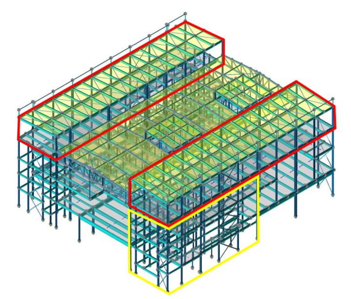
The original module design can be seen in Figure 2 below. One of the biggest problems that has developed during the design stage has been the addition to the original module design of a significant amount of steel (1000 tons +!)[. This has largely come about due to a number of factors, one of the most significant being the key stakeholders changing their requirements part way through the project. This has meant that larger Vertical Circulation Cores (VCCs) are required, increasing the steel required for the modules.
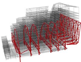
The revised design (see Figure 3) has seen the plant rooms on the roof reduced and the overall structural design simplified. Because of this simplification, larger columns and beams are now required, increasing the permanent loads despite the reduction of the plant rooms. I understand that the design was simplified for better buildability and easier ability to move by SPMT.
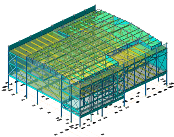
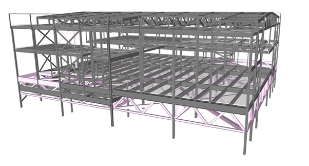
Additional temporary steel has also been required due to the need to keep the structure as rigid as possible during the SPMT move across the airfield. This has added a significant cost on top of the forecasted costs originally envisaged. Note in figure 3 that there is a lot of temporary cross-bracing to keep the structure rigid during the SPMT move. The cross bracing would prevent lateral movement though I believe it would not overcome torsional effects of the SPMT move, i.e. it would twist. Figure 4 shows a potential solution where the building sits on a truss. This uses more steel than the other design but allows the building to transfer loads much more effectively to the SPMTs.
Gatwick are negotiating with the designer on further compromises to this issue. The structural designer has added up to a 15% addition of steel to their calculations for connection detailing and 10% for ‘contingency allowance’. I’m not clear how they have come to these figures but do they seem right?
The modules also do not impose a uniform load, with the VCC part of the structure imposing more load than other areas. To mitigate this the SPMTs have been arranged in groups of three (see figure 5 below), much like the point support of a three legged wooden stool. Interestingly the module loading is distributed into four quadrants and it was originally suggested that the SPMTs also be grouped likewise. However, the SPMT contractor has stated that a four group method is not preferred due to additional control complexity during transportation.
All of this makes me wonder whether this method of construction, whilst quite innovative, has come with additional (expensive) obstacles. It may have been more economic to build the pier on site, with most of the work being done during operational stand-down hours at night. This however may have added additional time to the project. I look forward to seeing how this project evolves in the future.
What’s a TMR? – Traditional Vs. Whole Footprint Jump Form
Hello all,
It’s been a little while since I posted and I also realised I failed to follow through on my promise to add more information from my previous post ‘Innovative Jump Form System for the Residential Tower’ if you’ve not read that one feel free to check it out.
With the deployment of the junior course and what must be the impending deadline of submitting TMR 1, I though this blog might kill two birds with one stone and not take me too much time doing it.
- It might provide some insight on how someone has formatted and worded a TMR. This is by no means ‘the’ way of doing it its just ‘my’ way but it has severed to get me though with reasonable marks. I know how hard it was to get into the swing of TMRs especially setting up how you want them to look and feel.
- The topic of the TMR is a comparison of a traditional jump form system with the new style whole footprint system deployed on my site during my Phase 2. I managed to get myself a role as the Site Engineer for vertical elements and so was working with it daily. Thus this fulfils my previous promise.
At this LINK is the TMR itself along with the supporting Annex’s. I have also put in John’s comments and feedback following my submission so you can see the areas I could have improved, I have removed the marks suffice to say it scored over 50%.
Happy to answer any questions or comments if anyone has any. Hopefully this is useful to someone and doesn’t come across as self serving, believe me that is not my intent.
Bye Bye Tolerances
Yesterday on site we had an interesting discussion about an issue which has been in the background for a while, which everyone has been ignoring until it’s actually preventing concrete being laid.
Issue: The pavement thickness of the client has been specified as 150mm + 20mm. The precast secondary elements they are resting on are designed to deflect up to 40mm, the primary beams 6mm and the piles to settle up to 20mm. Whilst we haven’t actually been given FPLs (finished pavement level) by the designer yet, they are coming and we will have to be within +/-6mm to be compliant with the spec.
This is a similar problem to on Joe Murrows site, we can’t however back prop to limit deflection as it is over water!
This has raised the following questions:
- At which point does out liability end? FPL which change over time therefore so long as it’s less than 20mm is that okay?
- We have raised RFIs regarding which is the overriding factor, pavement thickness or FPL. We think it is going to be FPL, but if it is do we risk overloading the planks to get this? Atkins have designed for the concrete to be up to 45mm thicker to account for this, it is likely to be tight at midspan though…. This also doesn’t take into account the as built levels being lower that design.
- How do we monitor this settlement?
- Currently we are monitoring the levels at the four stages highlighted below. What we have suggested is that monitor selected areas, these include areas under the most loading and where the piles might be bearing on different boundarys to those it was designed for. These are being monitored weekly at top of plank level, point 3.
- At the moment it all comes down to resources, it is isn’t in the spec that we have to monitor it, therefore there is no money for it. A very shortsighted viewpoint I think as the elements listed below are intrinsically linked to knowing how much movement there is!
Areas where we are recording levels
Any ideas on how we could:
1. Cheaply and easily monitor settlement accurately?
2. Accurately measure Deflection?
Steel Pile Fabrication
G’day from Sunny Melbourne! this blog will be much shorter than my last!
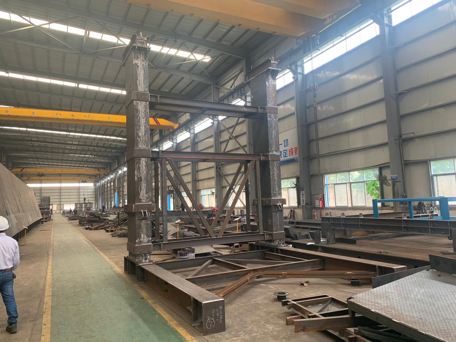
I’m sure all the Phase 2 guys remember our trip to NU Steel back on Phase 1 prior to Ex STEEL (that might seem like a life time ago already for some!), where John provided us with the opportunity to see the steel fabrication of gantry elements etc.
I thought I’d just share some photos of the fabrication process being undertaken by ABFI Steel Group (specialists in the fabrication of large diameter steel and pipes – https://abfisteel.com.au/), the specialist subcontractors that have been contracted to fabricate and deliver the steel tubular piles being installed for marine based pier foundations in the Maribyrnong River, Melbourne.

Typical marine Pier Section
The steel piles being installed in the river are 36mm thick, 2.2m in diameter (in the largest cases) and are being driven up to 35m RL. They have been designed to a maximum axial compression load of 28.6MN each. This poses a serious logistical challenge for delivery to site, considering the piles are being manufactured in Wacol, Queensland (only a 1021 mile drive – or 17.5 hours … in a car … ) and will be delivered by road. Clearly at 35m in length, the piles will require splicing on site, with sections being fabricated at roughly 16m sections. This will increase the number of deliveries, and of cause, creates issues with managing quality of splicing on site (a process that is being reviewed, in detail, as I write this). I will be involved in the Inspection Testing Plan (ITP) for these splices and will be required to ensure QA processes are conducted in accordance with the ITP.
Example of a Steel pipe Delivery by ABFI.
Below are pictures from the fabricator’s workshop of piles being fabricated (unfortunately, at over 1000 miles away, I was not able to pop over and get the pictures myself). As can be seen, some serious work is being conducted in this fabrication process as tolerances/quality are tight. This has led to some serious interrogation of the subcontractors method of works and QA system to ensure the piles are competent once manufactured.
I look forward to seeing the piles arrive on site and being installed as part of a complex method involving two marine barges to facilitate lifting and driving of the piles in the river.


How to pile through a railway station
As we aren’t able to add pictures to the replies, this is a quick post to answer Richard’s questions about the pile heads.
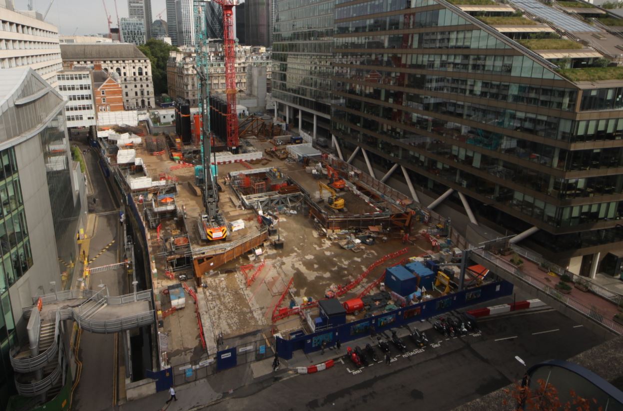
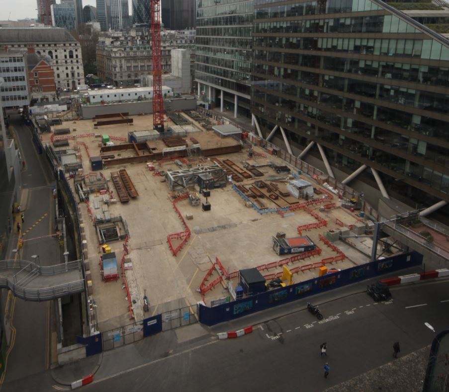
First things first – the time lapse camera looks west, from the ‘back’ of the site into the narrowest end. The view in my first blog An engineer without a site… for now. shows the remnants of a considerable amount of steel. This steel was formerly a piling grillage which can be made out below.
August 2018 – piling from the grillage at 21 Moorfields
The retained deck (RD),a composite steel beam and RC deck which is both the ground floor of this site and the roof of Moorgate station, is only rated for 10kPa UDLs so could not bear the weight of piling rigs. To get these rigs on site a grillage scheme was installed (3000T of steel – more impressive temporary works!) on plinths tied into hard-points on the RD.
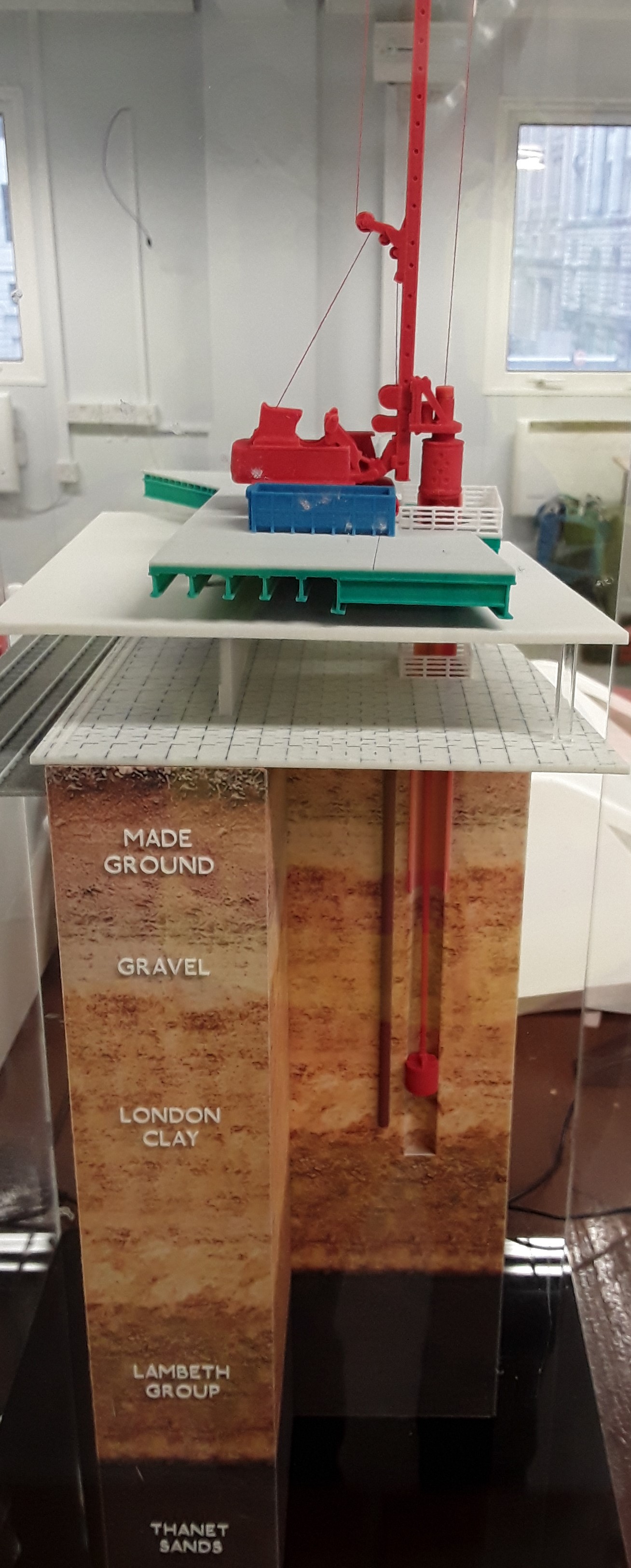
Piling model showing grillage, RD, rail platform, pile casing and soil strata
From this platform a steel casing was driven through the grillage, through the Moorgate platforms, through the made earth, through the gravel and into the London clay. The piles were then bored, from the grillage into the Lambeth beds, to depths of up to 57m.
The upper part of the pile acts a column through the station platform level and the casing remains in place. The piles are heavily reinforced in the upper sections in order to transfer moments imparted at the head by the base plate connections. The steel columns are fixed to the pile heads and tied into the reinforcing cage at the head.

Pile function
Moments are ultimately transferred by the piles to the ground beneath platform level as shown in the sketch above.
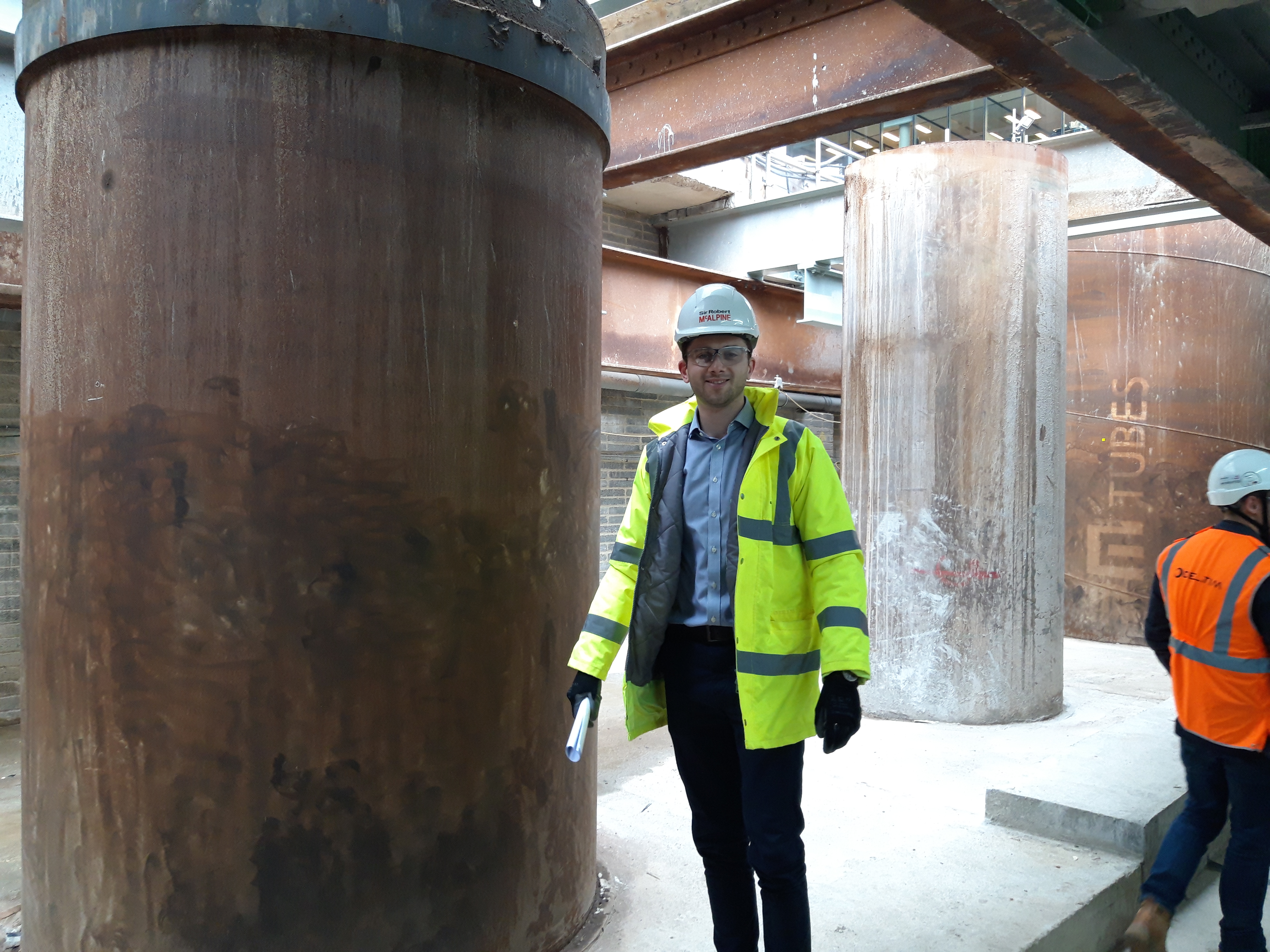
A smaller 1.8m diameter pile (with engineer for scale). Total 12 No 2.4m dia piles and 4 No 1.8m dia
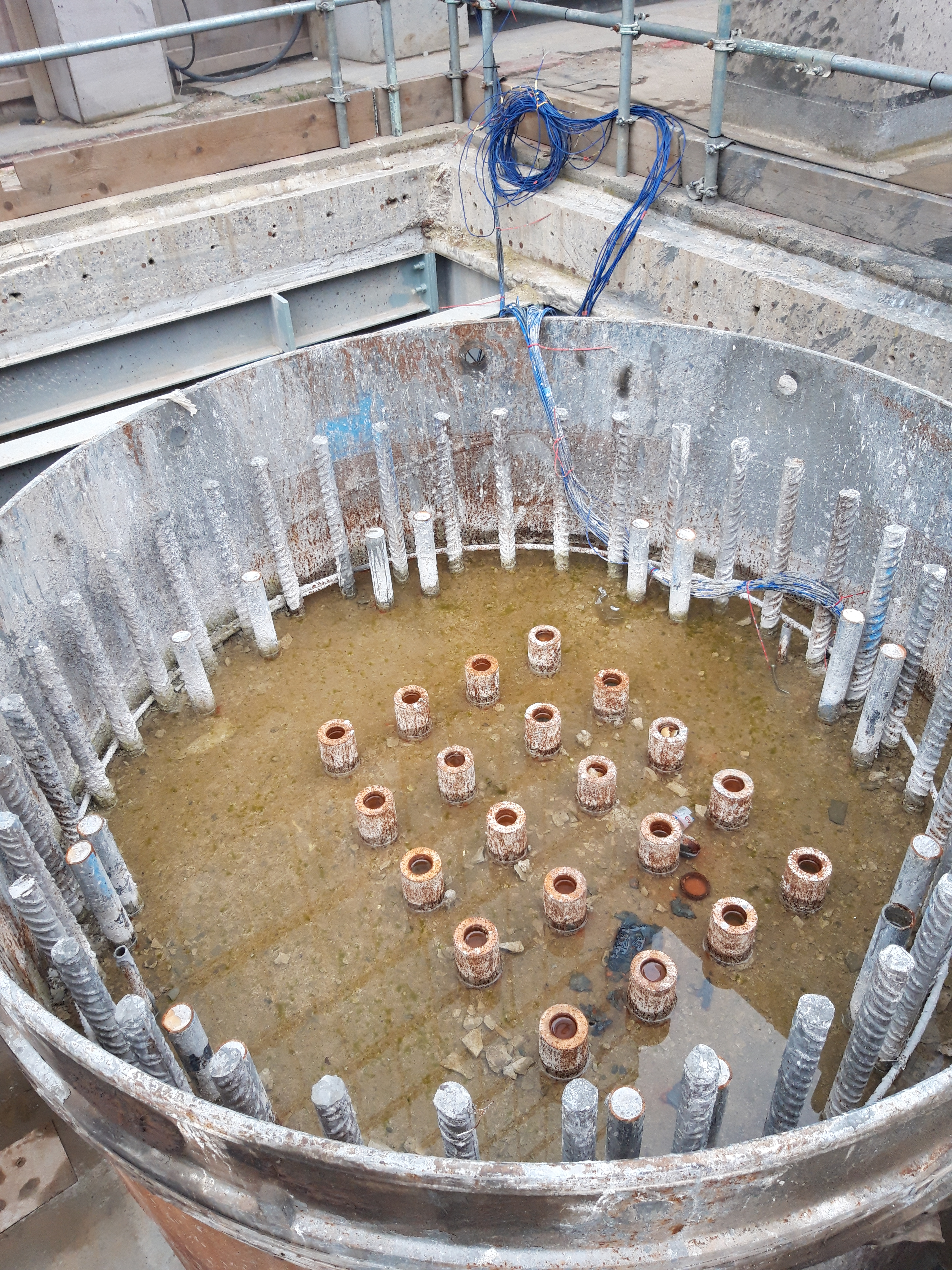
The piles have also been fitted with fibre optic strain gauges and grout tubes. The 5×4 anchor grid (seen below) was used to connect 4 No piles as reaction piles to the test rig for preliminary testing of a 1.2m pile. Axial design load on a 2.4m pile is 58MN.
Pile reinforcement (28 No H50 longitudinal bars with H16 links at 150mm centres), fibre optics and grout tubes.
Is this ground a risk?
I am currently sitting in a small team overlooking the demolition and then reconstruction of a car park in Woking.
The project manager has tasked me with setting the piling Matt levels to allow the piling contractor a flat even surface. We have decided on two piling Matt levels (ramp and car park) across the site with a battered edge between them to allow for the different ground slabs. The street level is approximately 28.5 to give an idea of how this will look on the ground.
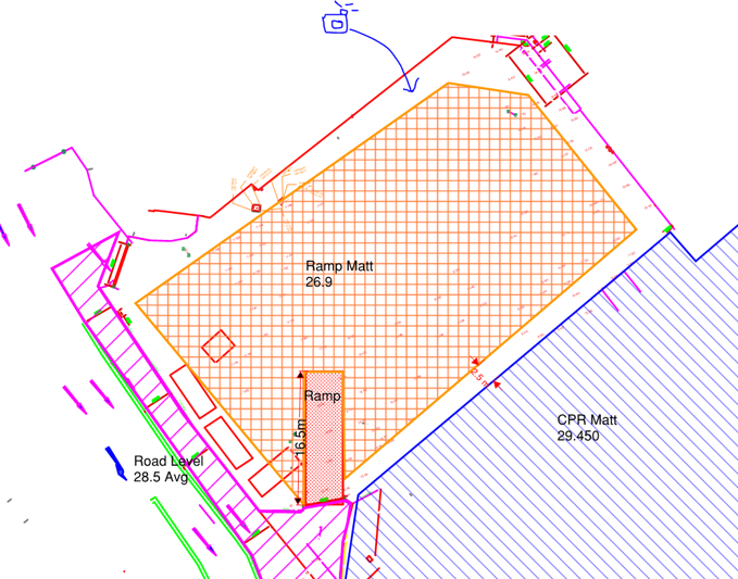
The ramp into the CPR cannot be seen on this drawing but does exist.
My main concern is with the level of the “Ramp Matt” which is adjacent to a Primark and Debenhams to the north and east. Looking at this problem it seems that we would be undermining the foundations of the existing buildings to excavate down to 26.9. Nobody seems to be able to tell me what foundations sit underneath Debenhams or provide any GI data beyond “it’s a clayey sand”. So it seems like an obvious answer, you need a retaining structure between Debenhams and the proposed piling Matt, but the plot thickens…
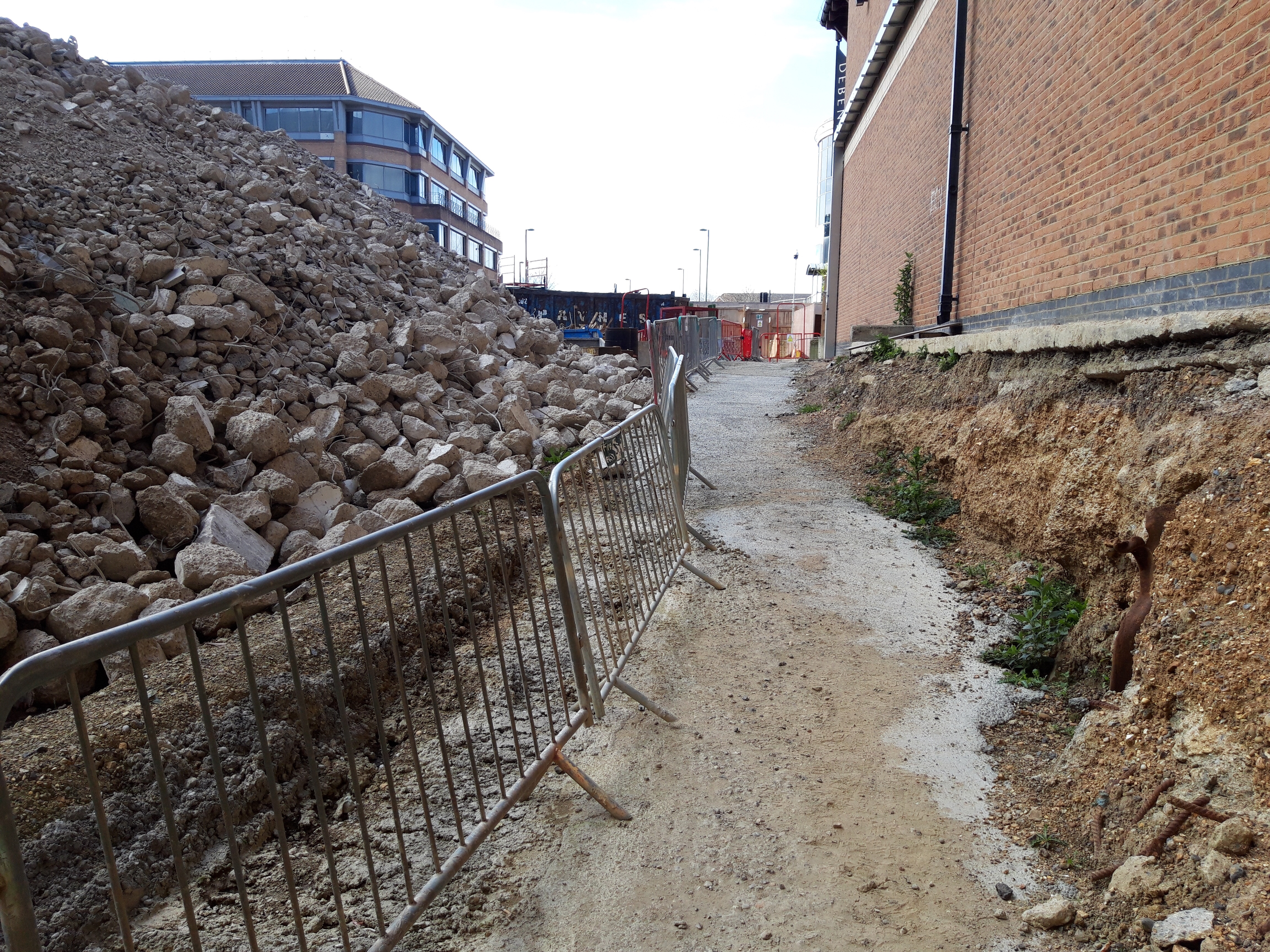
The ground has already been part excavated to allow access for workers and is standing freely. There is no evidence of the foundations under Debenhams and the ground seems to be holding. Supposedly this has been the case for the last 18 months. I asked who led with the initial excavation and it seems it was “just done”.
That photo is taken at the proposed level of the piling Matt but the ground rises into the far ground up to street level, the proposed Matt will remove that rise so the whole ground sits at the level the photo is taken at. It seems to me that the attitude is simply “it’s ok now so it’ll be ok to take the rest out” without anyone raising any alarm bells. Am I crazy or is this in need of an actual substantial design?
An engineer without a site… for now.
21 Moorfields will be a 17-storey office and commercial building, ear marked to become the London HQ of Deutsche Bank, in the heart of the City of London. It is a fascinating project that pushes the boundaries of light-weight steel structural design and threads the needle, in some cases quite literally, through the maze of site constraints. The project is estimated to cost upwards of £350M and is scheduled for practical completion in 2022.
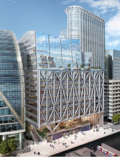
The East Face above the Crossrail station entrance
The development spans over the 6 live London Underground (LU) lines running into Moorgate Station and is immediately above the western ticket hall and access shaft for the London Liverpool Street Crossrail (CRL) station. The ‘ground floor’ of the site is also the roof of Moorgate Station and is a composite steel beam and RC slab deck supported on a series of piled columns known as the retained deck (RD).
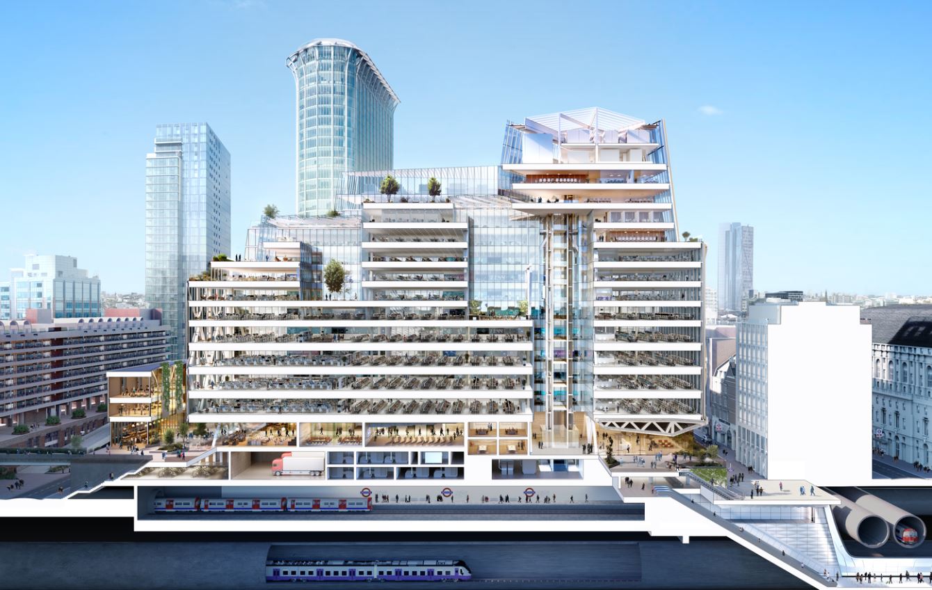
Architects impression showing the two LU lines and the Crossrail running tunnels – piling through this lot was literally threading the needle.
The steel superstructure spans 55m across the retained deck between two parallel rows of giant piles (the largest of which is 2.5m diameter and 57m long). Each pair of piles supports a 10-storey arch and truss to span the gap with a number of temporary works stages to ensure stability of the structure through to completion.
Truss and arch system with cantilevered East Face Truss
I have been assigned to manage the superstructure concrete package, starting with the pile heads, steel base plates and mezzanine deck, moving onto deck and beam work at every level.
All very good but there is one small problem… we aren’t allowed on site.
The early works contractor (Mace), failed to secure the second-stage (i.e. superstructure) contract and so are vacating the site – slowly. Until they do so (the end of this week) we are sitting in an office down the road with only the high camera for site updates. To complicate this, the D&B contract between McAlpine’s (my lot) and the client (Land Securities) has yet to be signed so when works do start on Monday no one will be under contract to anyone else.
The closest any one can get to site until Monday
This enforced exile has given me ample opportunity to read into my works package and spend time with the QS team to fully understand their processes. I have also already experienced almost every type of contractual arrangement I can recall from PPO and PCM – we have PCSA, Letters of Intent, Contract Administrators Instructions, Frameworks and, hopefully soon, a JCT D&B contract.
Come Monday I can sharpen my stadia rod and don my finest hi-vis vest for a bit of Engineers in the Wild excitement on site. Until then I’m back to my bills and quotes, spreadsheets and delivery notes.
Scale of Temp Works
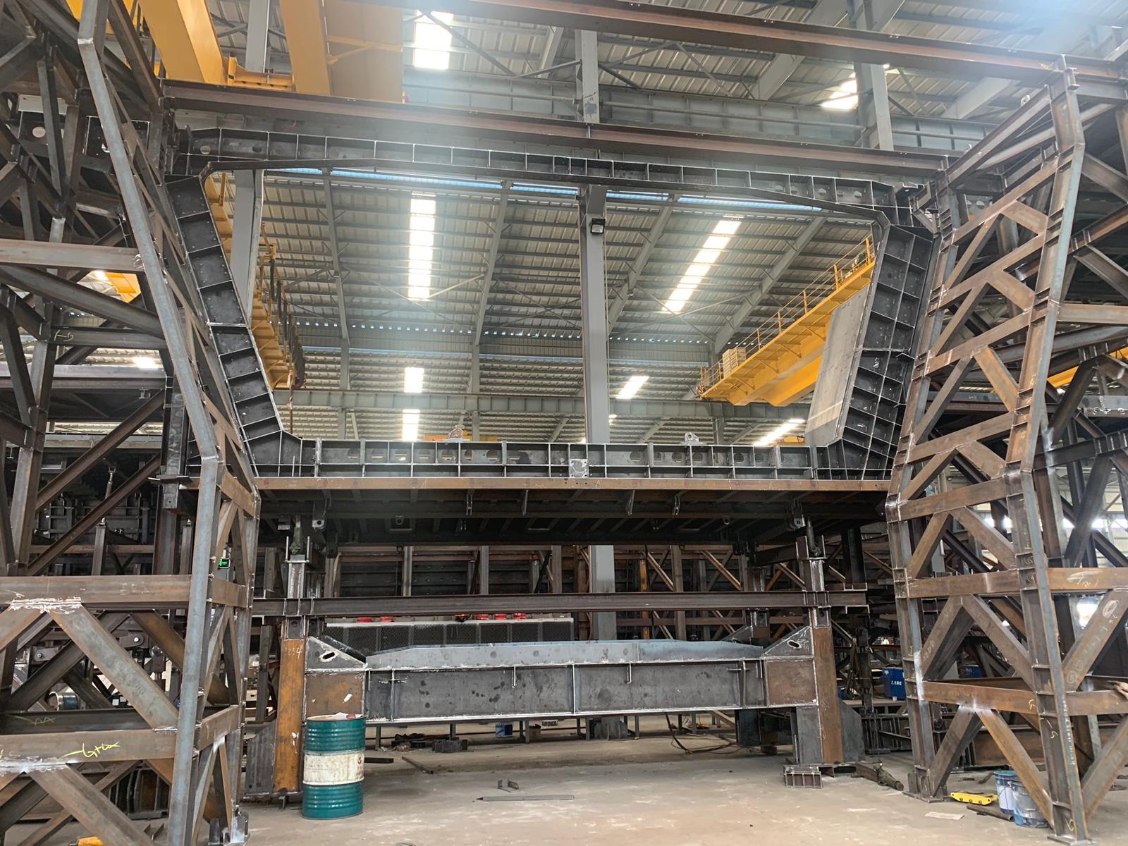
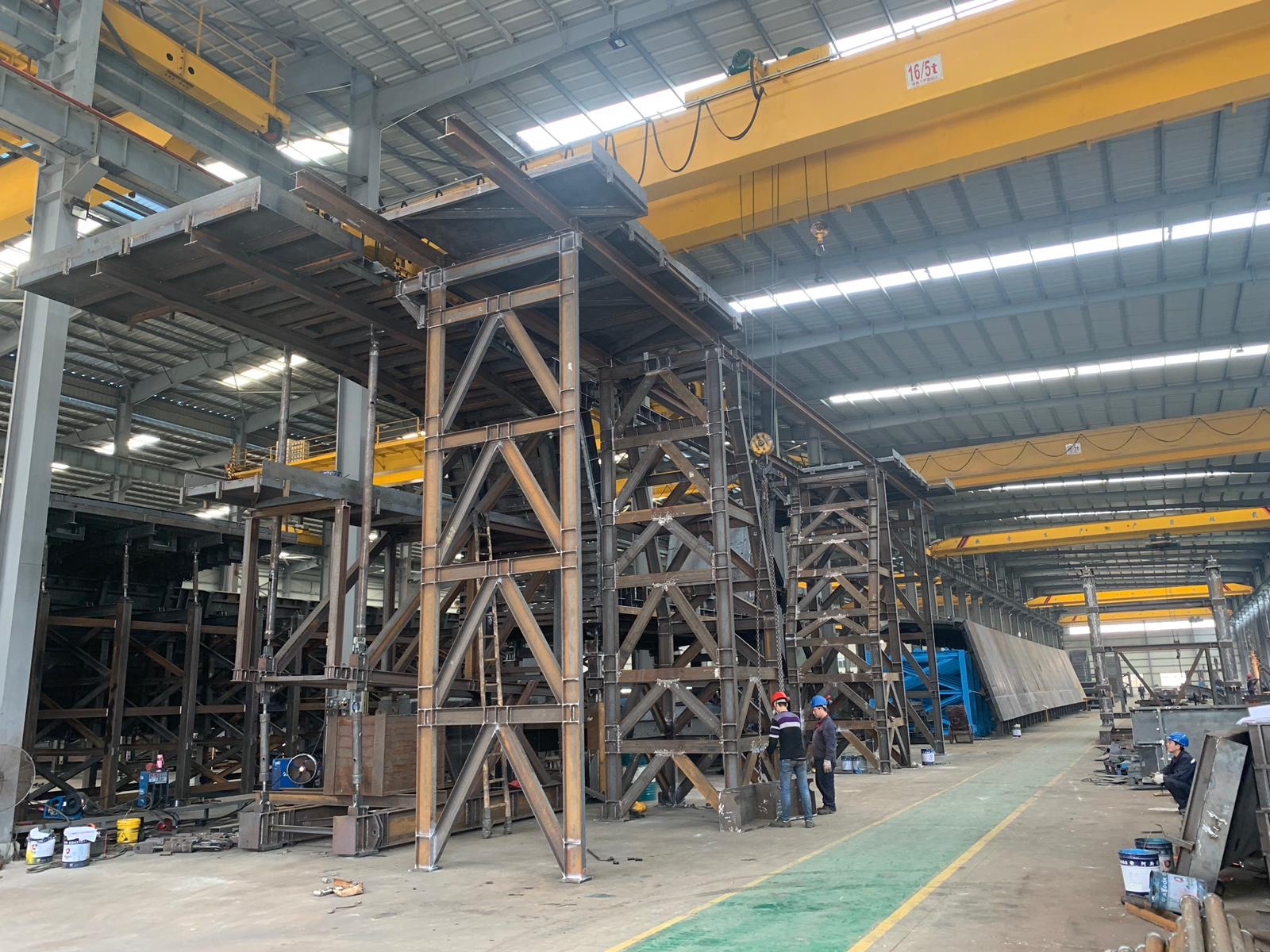
John I remember you telling us in Phase 1 you are always amazed at the scale of temp works that are involved in creating the permanent works. For my project the team are spending AUS $2.5M on establishing and running a precast yard. Below are some pictures from the trial erection currently underway in China of the pre-cast bridge segment forms. The forms are designed to be adjustable to accommodate the curves with the new segment cast next to the previous one to ensure continuity.
The average segment will be 11m long, 2m wide and 4.7m high. I’m not sure what the size the forms are but you can get an idea of their scale from the size of the people in the photographs. I’ll post more detail when they are installed on site and I understand more.
Engineering surveying
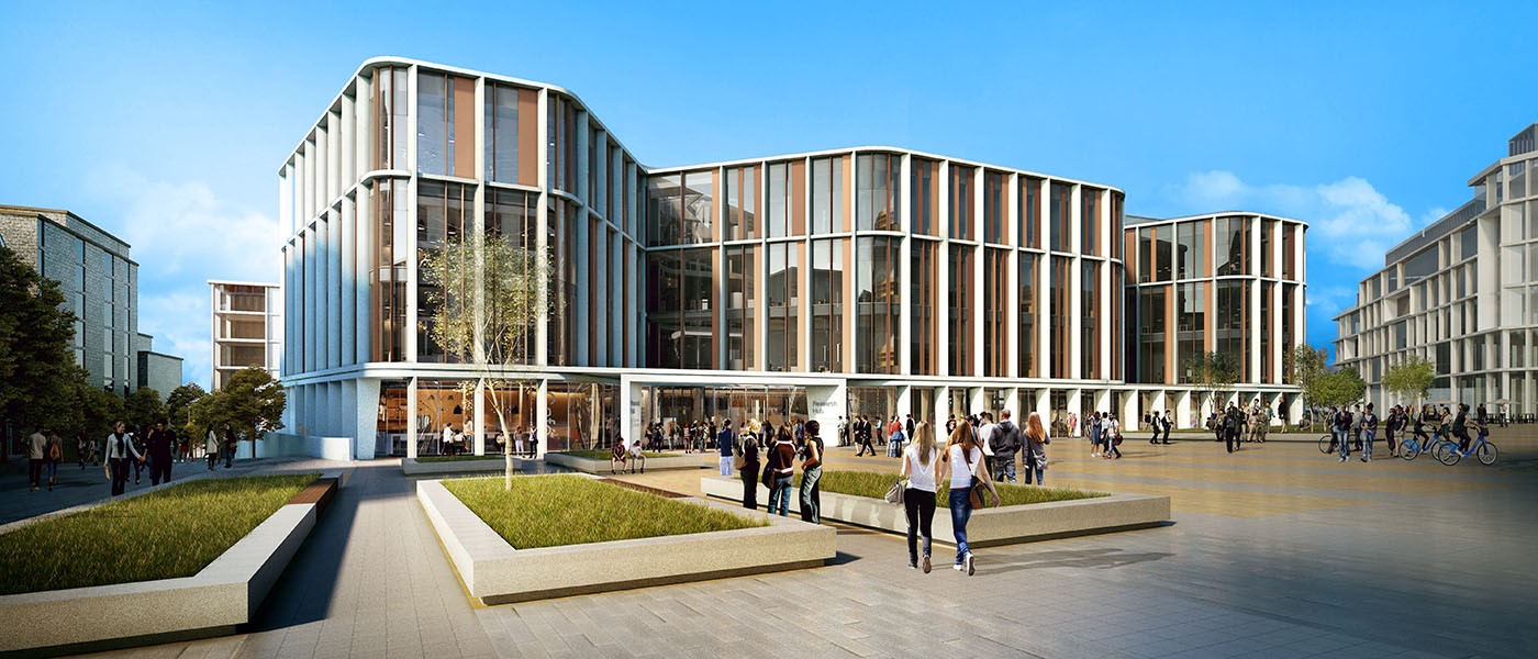
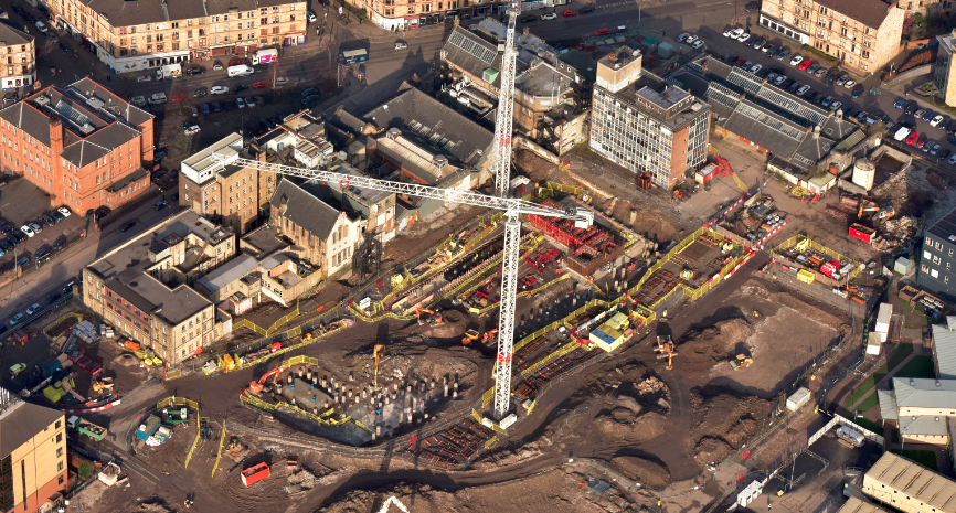
Introduction. I am now in week 3 with Multiplex on the University of Glasgow campus development, working on the £80m Research Hub project In general, the structure is a 6 storey reinforced concrete frame using flat slabs, piled foundations, steel frame roof level, pre cast concrete cladding and curtain walling. Piling finished in February with the rest of the substructure works in progress.
Issue. Along with the site engineer I have been looking at ways to improve the efficiency of our construction layout surveying. Particularly our methods used to control elevation, horizontal position and dimensions. At present we use a co-ordinate based setting out system with a Leica Total Station and are looking to improve our workflow prior to conducting as builts and setting out of MEP systems. At the moment 1 of 2 methods is typically used:
Method 1 – The junior site engineer is using a manual method. Using a dimensioned drawing, offsets from gridlines are calculated then checked on site using a reference line function.

Method 2 – The senior engineer has been replicating the project Revit model for the element, then exporting the lines to Autocad. From here the intersections are exported as a CSV and checked using the stake points function.
Neither method is ideal and so we have been looking at 2 alternatives.
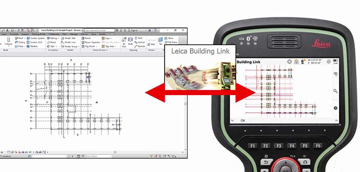
Alternative 1 – Leica Building Link. This allows points to be added directly to the federated or structural Revit model. These can then be exported as an XML onto the Leica and re imported on completion to provide as builts.
+ Free, easy to use.
– Only compatible with Revit 2017, manual input method creates user error and is time consuming.
Alternative 2 – Autodesk point layout. Similar to Leica Building Link this can add points directly to the federated or structural Revit model. It has an automatic function and ability to create naming conventions.
+ Can quickly generate large numbers of points (possible to tie in with Revit families), compatible with Autocad and Navisworks, can create slab analysis heat maps.
– Relatively expensive, more complex to use compared to Leica system.


Further considerations:
Trust. Do we trust the federated /structural Revit model? It is seen as the point of truth but may contain errors. Therefore is it better for the contractor to produce their own model to identify buildability issues in advance? This can then be checked using clash detection.
Best practice. This Autodesk seminar video outlines the use of a point layout approach by a contractor in the US (https://www.autodesk.com/autodesk-university/class/Best-Practices-Utilizing-Point-Layout-2017#video). They discuss the benefits of system but note that it has taken years for them to optimise the way they integrate it and to design a workflow process.
Summary. Our current methods of engineering surveying are inefficient with room for improvement. Does anyone have experience of similar issues or advice on successful methods used in the past?
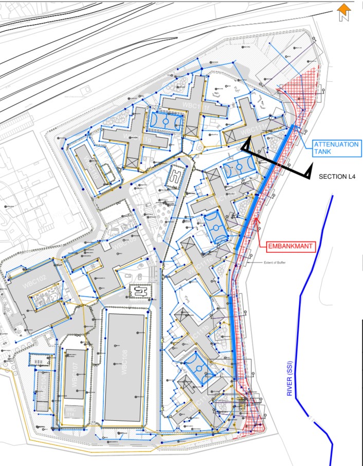
Drainage tanks in slopes
My latest Ph3 task is to coordinate the design of a reinforced slope with a surface water attenuation tank buried inside the embankment. Every part of my engineering judgement makes me think this is a bad idea – the challenge is to now engineer a solution that will work.
Background
The site lies on hill adjacent to SSI (a river and marshland). Two major risks with the sloping site;
- Excessive surface water run-off.
All surface water drainage requires attenuation to limit the discharge into the river. The redevelopment work will increase the capacity and size of the facility by 4-times the original.
- Major cut and fill exercise.
Project design specifies split levels and requires major cut and fill exercise to create plateaus for several large buildings.
Initial Design
Initial storm drainage design located attenuation tanks under sports pitches. This is an ideal scheme; large areas with minimal loading permits shallow excavations for large capacity tanks.
The Construction Phase Plan could not be achieved in unison with this scheme. Large laydown areas were required to facilitate the erection of multiple pre-cast concrete buildings simultaneously. Freedom of movement for heavy crawler cranes was integral to critical path activity. Any buried attenuation tanks would not have been able to handle these loads and the scale of temporary works to mitigate damage was not cost effective.
A large (350m-long, 6.0m high) retaining structure is necessary along the Eastern edge of the site to achieve level ground. Initial design concepts sought to utilise excavated Oadby Till (Clay) to produce a cement stabilised embankment.
Issues
Boundaries – Need to move the location of the attenuation tanks. The only available space where the tank could be buried deep enough to handle heavy construction traffic was adjacent to embankment.
Properties – Contractor is keen to use materials won on site to reduce costs (and claim some sustainability benefit). The clay alone does not have the capacity to achieve the 40-degree slope required. Confirmation of material strength following cement stabilisation can take 35+ days. This would not work with an already compressed programme.
Ground Water – A second design to reinforce the clay has been proposed but in an undrained state, the tails of geogrid would clash with the only available location of the tank.
Contamination – An underlying mudstone layer has high sulphate levels that are detrimental to cement stabilisation. Some of the boundary layers are ill-defined and risk of sulphates with the clay exists – further justification to reject cement stabilisation.
Options
My role is to understand if the following concept is achievable;
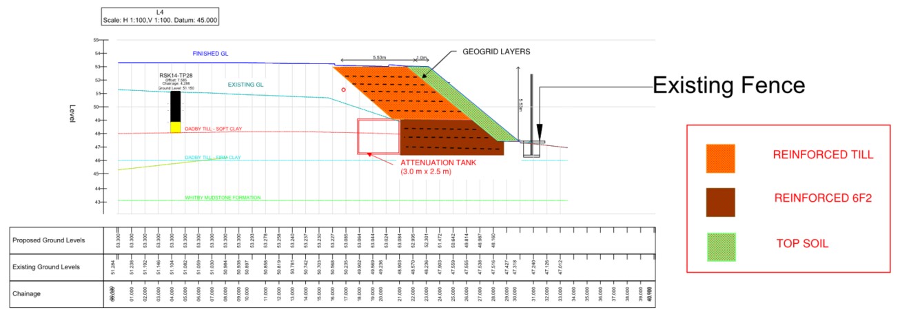
Major demolition works on site have generated a source of granular fill. This screened 6F2 could be used to form a steeper embankment and prevent a geogrid/tank clash due its superior characteristics. Preliminary calculations suggest there is insufficient quantity of this on site to form the entire embankment.
A hybrid embankment could be the solution.
Using drained granular fill to support the lower section of the embankment means shorter geogrid tails can be used next to the tank. The cut and fill clay will form the upper section of the embankment where the geogrid tails can extend above the tank. This maximises the re-use of material won on site.
I know others have looked at earth embankments – any thoughts?
