Archive
Screw it!!
Another quick blog about something that came up in conversation yesterday with my Phase 3 mentor, which potentially has application to military construction and disaster relief operations.
BLUF
If not already used, could screw piles have an application for short to medium term RE infrastructure projects and limit groundworks and the need for reinforced concrete foundations?


BACKGROUND
My mentor here is chartered with the ICE and spent 10 or so years working in the UK, before coming out to Australia. One of the pieces of evidence he used in his CPR was his introduction of screw piles to the highways agency for the erection of gantry signs along carriageways.
Apparently screw piles had been in use by the rail industry for some time, but the technology hadn’t made its way into other sectors. He was working on a roads project somewhere along the M6 near Birmingham which included the installation of a number of new overhead gantry signs. Traditionally the foundations for a gantry would have been one of either;
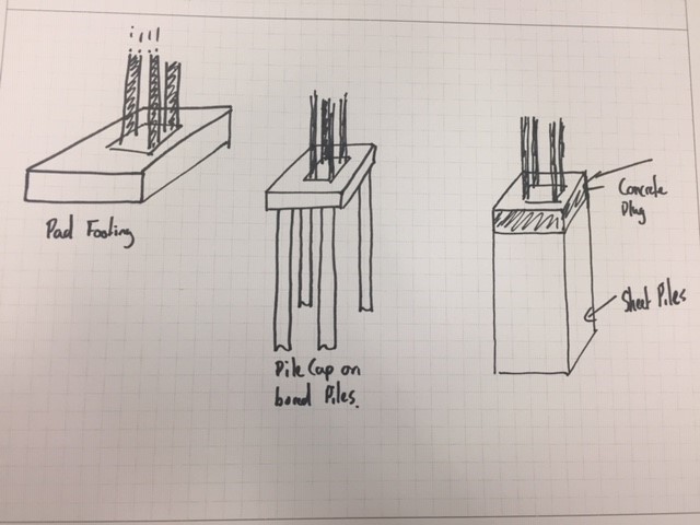
- Concrete pad footing large enough to deal with overturning actions
- Pile cap on top of bored piles
- Sheet pile box with concrete plug in the top.
Some of the considerations for the erection of gantry signs and any other roads infrastructure are;
- Time on site (Reducing the need for traffic control measures and risk to road crew of working next to live traffic)
- Ability to remove/relocate structure to accommodate future development, road widening etc.
He identified that the traditional methods described above weren’t necessarily suited to this as piling works take time and equipment, and concreting needs prep and curing times. Additionally you aren’t left with too many options but to break out the concrete if you need to move or relocate assets, which isn’t very sustainable especially if your leaving 10 or so metre piles in the ground.
SCREW PILES
Screw piles on the other hand can be installed very quickly and need minimum plant, the attachment for screwing in the pile can be fitted to an excavator or skid steer for example, so very much scalable;


Once installed a simple grillage can be bolted to the piles to provide a connection for your gantry. Once the gantry is no longer required, the structure can simply be dismantled, the screws piles removed and re-used elsewhere.
MILITARY APPLICATION?
Something as simple as this, strikes me as a low tech, adaptable foundation solution which can be rapidly employed across different environments and avoid the need for lengthy and costly groundworks. From my brief reading, it appears the bearing capacity/hold down force required is achieved by screwing in the pile (in the example I looked at typically 2m sections which bolt together) until a specific torque is reached which determines you have reached the desired capacity. This suggests to me you might be able to avoid the need for lengthy geotechnical investigations (to some extent) and simply extend your screw piles to reach the desired capacity. This might be an over simplification…I think you can summarise the pros and cons as follows;
PROs
- Low tech
- Limited plant requirement which is standard to a plant troop
- Scalable; can easily up size piles or increase the number of piles
- Flexible; if the pile doesn’t achieve the desired capacity add sections and keep going
- Avoids ground works (especially in poor or wet ground)
- Rapid installation
- Re-useable/sustainable
CONs
- Limited capacity compared to traditional piles (This might not be an issue as unlikely to need significant capacity);
Fig below show the ultimate tensile capacity (take as a displacement of 20% of screw dia) for 100mm dia screws with different helix spacing tested at 3.05m (circles) and 6.10m (triangles). Material was 2m stiff silty-clay overlaying a deposit of lacustrine varved clay (Undrained shear strength 200KPa and 30KPa)

Note: spacing of helix’ is important in determining whether the plates act independently or in a cylindrical shear method
- Logistic burden; Probably not going to be available locally so would need to be freighted to op theatre. concrete on the other hand can generally be sourced locally
- Not suited to rock; not sure what strength of material would preclude their use.
while I was looking into these it got me thinking about a JFEE I did in Kenya a few years back which included the construction of a community centre. The previous Sqn had a number of issues with the foundations, which if I remember correctly was mainly down to the weather and rain filling the excavations and shrink/swell issues with the murrum. Could this potentially have been avoided through the use of screw piles? Screw piles seem equally suited to disaster relief operations and is seismic areas the ability to re-use them could provide an advantage over concrete foundations which presumably would become U/S after an earthquake?
THOUGHTS?
I’d be interested to hear what people think about the application of these for the Corps, or have we already used them? Has anyone come across them on one of their projects ?
“A good consultant does what we ask of them, a great consultant challenges our thinking”
I thought I would just share a quick blog after I attended a ‘Design to innovate’ workshop on my Phase 3 attachment with Aurecon today.
Aurecon is big multi-national company formed out of the merger of Africon, Connell Wagner and Ninham Strand in 2009. It’s main markets are Australia/NZ, Asia and parts of Africa. Its big selling point is that it claims to offer a different service from ‘all the other consultants out there’ and it has been described as the Google of the design world.
while I have initially been a bit cynical about this self styled approach, the quote I have titled this blog with came up in my workshop today and I thought it was quite good. The workshop then went on to explain the background to Aurecon’s thinking and introduced the ‘Blue Ocean Strategy’, a concept which was new to me and one I thought worthy of sharing for those who haven’t come across it. Rather than try and explain it myself, the short 2 1/2 minute video below will give you the idea;
Aurecon are trying to provide the next level of service in design consultancy, by improving the client experience and pushing the boundaries of the traditional design service. An example of this is that they are actively identifying future issues in their market areas, designing against them and them approaching clients with a solution to a problem they don’t necessarily yet know they are going to have.
I am not yet 100% convinced how much of what they are offering is new (and given my lack of experience I have nothing to compare against), but am interested to see what I pick up over the next couple of months. Maybe everyone else consultant has a similar pitch..?!
Introduction to Civil 3D
Introduction
Upon arrival at my Ph3 Design Office my Line Manager had me complete a Civil 3D AUTOCAD course. I am sure that many of the Civils are most likely using this or a similar software package in their design offices. However, if any of you aren’t or are only just beginning to use it then I felt this would a useful opportunity to share my experiences with you. Additionally the course deliver has permitted me to share my electronic course notes, which are a useful handrail for using Civil 3D’s specialist features.
Recommendations
The Professional Engineer Wing are invited to note the following recommendations:
- PEW should become an AUTOCAD approved course deliverer. This would formalize the CAD lectures on the course and enable students to achieve recognized AUTOCAD qualifications, which would aid them during Ph2 and Ph3.
- Civil 3D should be taught, to the Civils, as part of the PET course. As AUTOCAD is already taught as part of the course, it would be useful for students to know and understand how to use the specialist plugins available to civil engineers.
Civil 3D Specialist Features
The following is a brief summary of the specialist features that are incorporated as part of the Civil 3D software program:
- Digital Terrain Modelling. Civil 3D allows you to directly input survey data and from that data build a topographical surface. It will also reference the nomenclature of those points to input terrain features like trees, manholes etc. automatically.
- Road Design. Civil 3D has specialist features for designing alignments, profiles and corridors. Additionally it has many roadway features such as junctions, roundabouts etc. preloaded. It references data from legislative safety standards and will adjust the design to ensure they’re met.
- Grading and Earthwork Volume. Civil 3D enables you to grade with ease, this can be used for road design or simple surface manipulation for drainage etc. Additionally, it is able to use the data from grading to determine earthwork volumes.
- Gravity & Pressure Pipe Networks. Civil 3D is preloaded with the vast majority of conceivable pipe network fixtures and fittings. This makes designing and understanding the flow in pipe networks as simple as drawing polylines.
For more detailed information on how to use the various specialist features in Civil 3D, please refer to the course notes below.
Summary
So far in Ph3 I have been responsible for designing surfaces using Civil 3D to ensure that storm water on a new development will drain in accordance with the Maryland Department of Environment’s state legislation. Additionally, I will soon assume the design responsibility for foul water drainage system as part of a new military facility.
I have found the specialist tools in Civil 3D to be highly effective and huge time saver, in creating the designs for the aforementioned projects. I wholeheartedly recommend the software to my peers and hopefully you will all find it as useful as I have.
Course Notes
What goes up…must be reused?
I’m on Phase 3 with Arup’s infrastructure team looking at urban redevelopment design so this caught my eye and got me thinking…
An article popped up on the company internal blog asking for design and construction experience of pre-cast RC multi-storey car park (MSCP). It stated the project drivers being programme and durability. Nothing out the ordinary so far.
A response was received within minutes based on recent experience that clients are now more aware of their social policy/agendas (sustainability) and constrained investment potential in ‘fixed’ structures. They state clients are favouring semi-permanent and flexible structures over traditional builds with greatest possible design life. The example given (below) was a ‘shape-shifting’ and deconstructable MSCP as the client sees autonomous vehicles making a traditional MSCP obsolete within a decade. This suggests design for deconstruction (DfD) and adaptability has the potential to be as if not more valuable to clients than durability…
https://www.cbc.ca/news/canada/calgary/east-village-calgary-parkade-platform-mixed-use-1.4855681
Planet. The design for deconstruction concept is founded on waste reduction so sustainability unsurprisingly. Technological development and sustainability incentives (UN SDGs) are driving up delivery efficiencies. Time-down, Quality-up.
People. The designing-in of deconstructability needs to happen at the project concept stage. Are rapidly changing attitudes and wider socials drivers such as autonomous vehicles (excuse the pun) triggering strategies away from permanent structures? Cost down.
Profit. Are clients/developers seeing opportunities in the two paras above to turn a quicker and more efficient profit? T-down, Q-up, C-down = Profit-up
Has anyone experienced similar quasi-permanent structures or concepts in their attachments? Any key considerations?
I wonder whether there is even utility in the concept for Defence – quasi-permanent bases for a decade or two say e.g. to deal with re-basing issues? Knowing defence, I suspect for the near future we will see more erratic rather than slowly evolving cityscapes instead…
Marginal Gains….
I am now a couple of weeks into my Phase 3 attachment and while digging into some information on a project I am involved in I picked up something which I thought was quite interesting and worth putting out there for comparison against other design consultants.
Reading the Risk Assessment which was completed during the tender stage I came across an entry which highlighted a predicted profit margin of 60% as a risk and a comment which indicate this was an “aggressive” tender in the hope of securing the bid and a foot in the door for future works on this major project.
I was (maybe naively) quite surprised at this. Not having any experience of working in a design consultancy I didn’t really know what to expect, but this seemed a pretty significant margin. I had a chat with my design manager to get a better understanding of the situation and found out that actually 65 -70% is the normal range on projects and 58% is the minimum allowable margin.
I was curious to know how this bears up against other people’s experience, particularly on jobs in the UK and US vs Aus?
Stadium Porn
After a week of button bashing, trying to understand why Tekla was spitting out mental wind loading values on a prison block steel frame design, the following came as welcome relief…
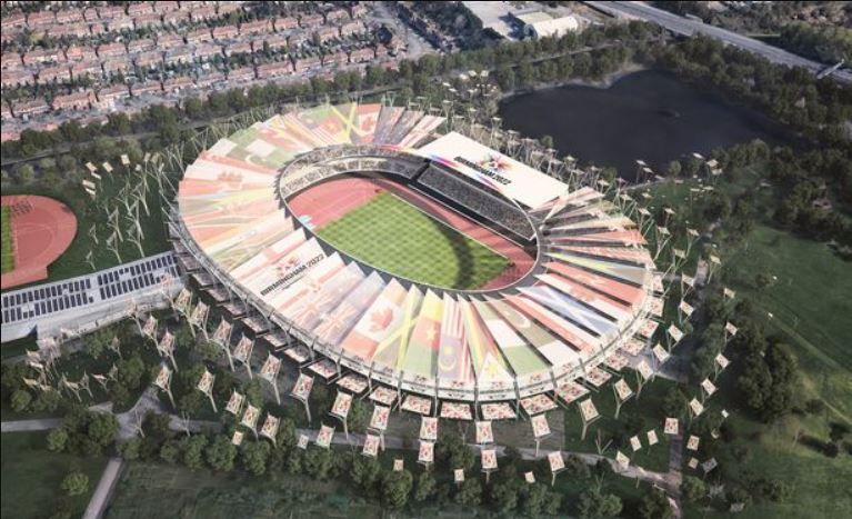
Fig. 1 2022 Commonwealth Games stadium artist impression
My phase 3 is with Arup and I am working out of their ‘campus’ in Solihull, Birmingham. Today the head of structures set the challenge of a concept design for the 2022 Commonwealth Games stadium. I wrongly assumed he was joking when he called everyone into a meeting room, handed out some rolls of tracing paper and declared “the architects arrive this afternoon, you have 30mins to sketch a concept for the new stadium, be prepared to present your scheme to the group and demonstrate how loads transfer to the ground”.
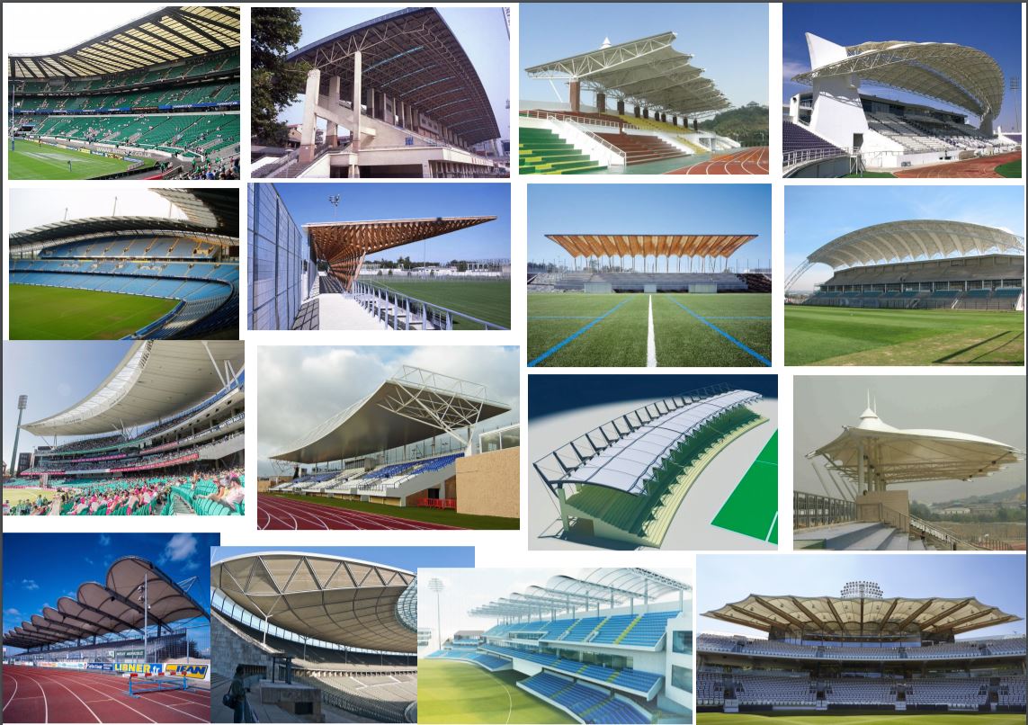
Fig. 2 Stadium porn
Obviously the architects are not coming until next week but it was cool to see the half dozen concepts get critiqued. We are not forecast to start developed design for a few weeks and there is still opportunity to take influence from existing stadia.
Has anyone been to a venue that impressed? The AAMI in Melbourne was used as a case study to showcase recent Arup success.
Please can you share your suggestions on here and I promise to credit you if it gets taken forward…
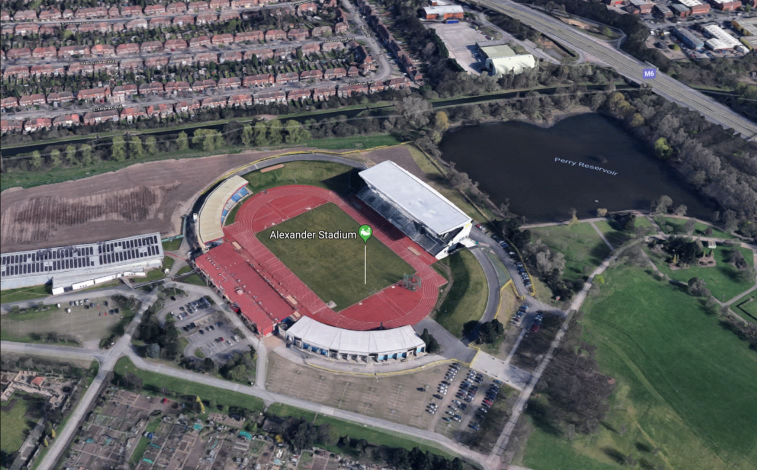
Fig. 3 – Google image of existing Alexander Stadium
Alexander Stadium will be redeveloped into a 40,000 seat capacity but has to incorporate the existing East Stand. Both the North and South stands will be de-scoped after the games to leave a legacy 20,000 seater.
Birmingham’s Alexander Stadium in £70m revamp for 2022 Games
A sign of the times….
A quick blog to share an event that happened this week in Melbourne, which reiterates the risks involved in design and construction. On Monday, I started my Phase 3 placement with the Transport and Infrastructure (TI) section of WSP. On Wednesday, a “bit of a flap” occurred in the office as an overhead road sign and part of the gantry collapsed onto a car (to note, there was no strong wind on that day). These links will take you to the news articles and dash cam footage from other vehicles travelling on the freeway. Luckily the driver of the vehicle suffered only minor physical injuries.
The freeway was re-opened to the public less than 12months ago following a $1.3billion upgrade and widening project. WSP were part of the design team and responsible for some of the gantry designs for Stage 2. CPB delivered the construction. Following the event the Client (Major Road Projects Authority) and the asset manager (VicRoads) initiated an immediate review of the full design documentation, construction documentation and remaining gantries to identify any additional risks (and also blame). Fortunately, for WSP, it turns out that this gantry is not one they designed – which was a relief for many in the office. The investigation is still ongoing, but it is believed the failure was in the gantry connections – either a poor design or not constructed to the design (current thinking is the latter and fault is with CPB QC procedures during construction). I will update the blog in the comments when the report comes out identifying the fault. As I start my first week in design, I thought this was a good reminder of the risks involved even with simple structures.
Plunging within an existing building
Quick blog for interest as seems to be something that isn’t done particularly often.
Shell House facade is to be retained (previous blog (‘loads of temporary steel’) explains the retention structure). I was asked how the plunge columns were constructed prior to demolition. Here is how it was done:
- Entrance from Wynyard lane increased and slab demolished to allow access for rig to drive in and down the ramp to basement level.
- Demolition of two slabs to allow access for lift in of columns (existing void from L1 up (see 1st and 2nd photo)).
- 21m plunge columns constructed.
- RC crane base cast on top of the 4 plunge columns.
- Stability core and retention system built from crane base.
- Crane tower constructed within stability core.
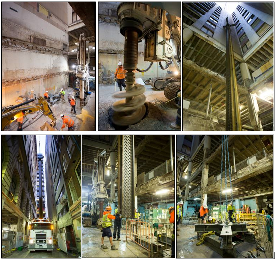 Figure 1 – Plunge Column Construction Photos
Trying to avoid skill fade. Trying.
I finished the PET Cse (Civil) in 2016 and subsequently found a reasonable amount of Attribute 1 & 2 ‘stuff’ in my time as an STRE 2IC to try and stay competent. You may recall from your visit to Chilwell a few months back, I mentioned the need to actively seek to find faults in Clk Wks work, firstly to ensure that what is designed won’t fall over and kill horse riders in Cyprus, but from a selfish perspective, to avoid the dreaded ‘skill fade’ everybody uses as an excuse to palm stuff off to Reservists in Arup.
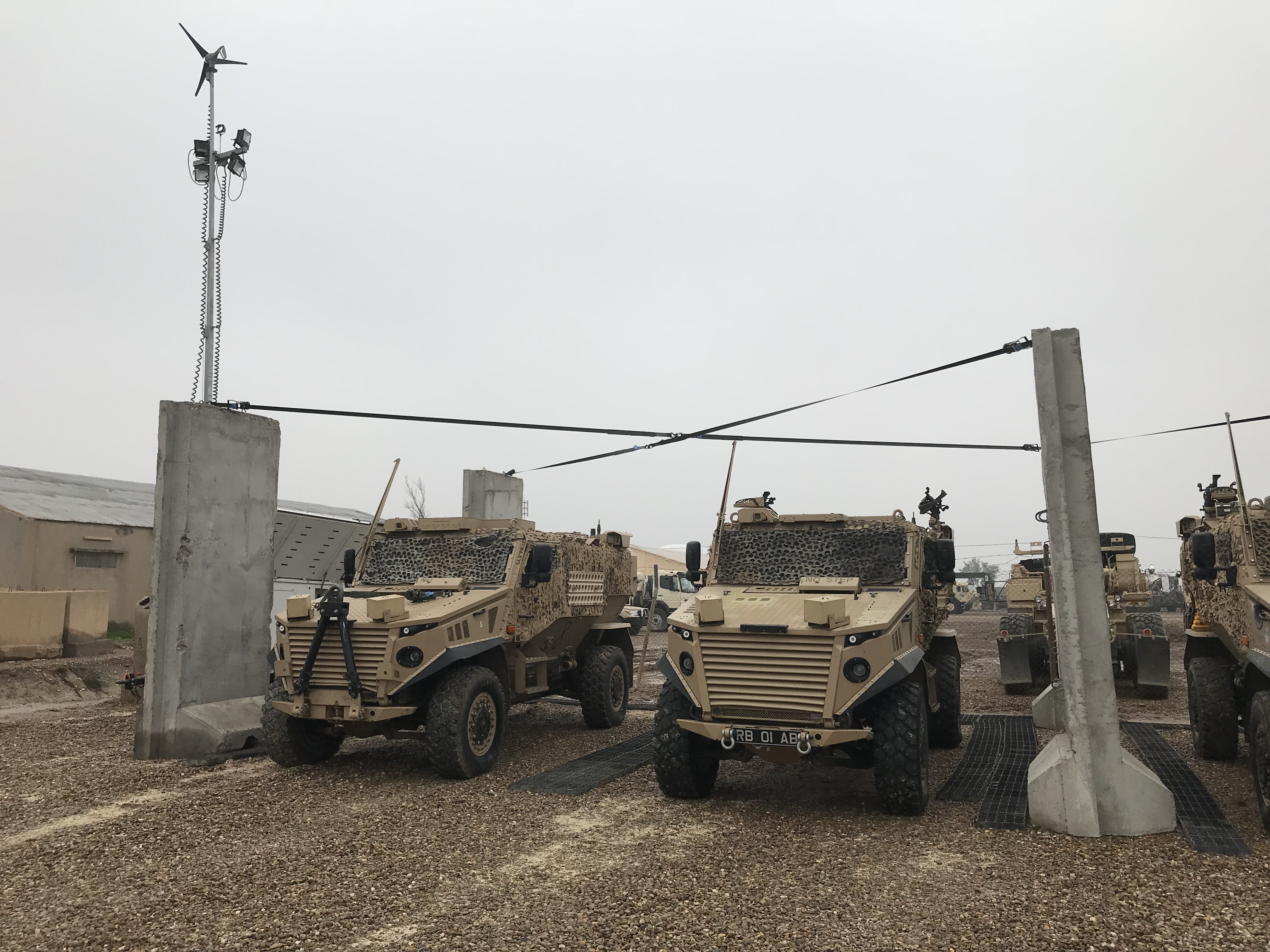
Anyway, I am now employed as one of two Infra Requirements desk officers in JFSp (ME), looking after Infra across the entire Broader Middle East. Yesterday I was walking around TAJI (Iraq) and noticed this:
T-Wall on the piss (coincidentally missing a tie)
Surface water and drainage ditch filling up
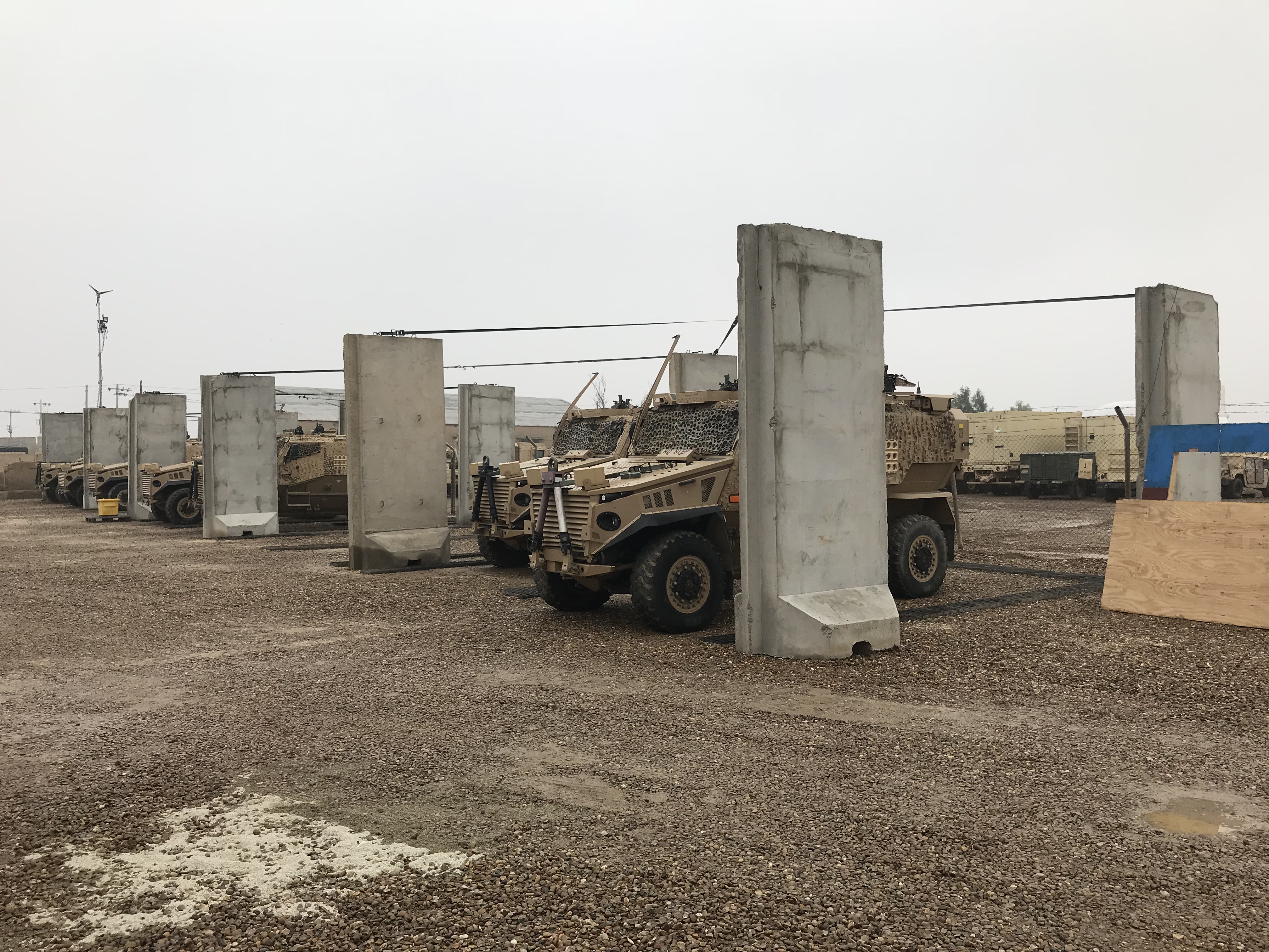
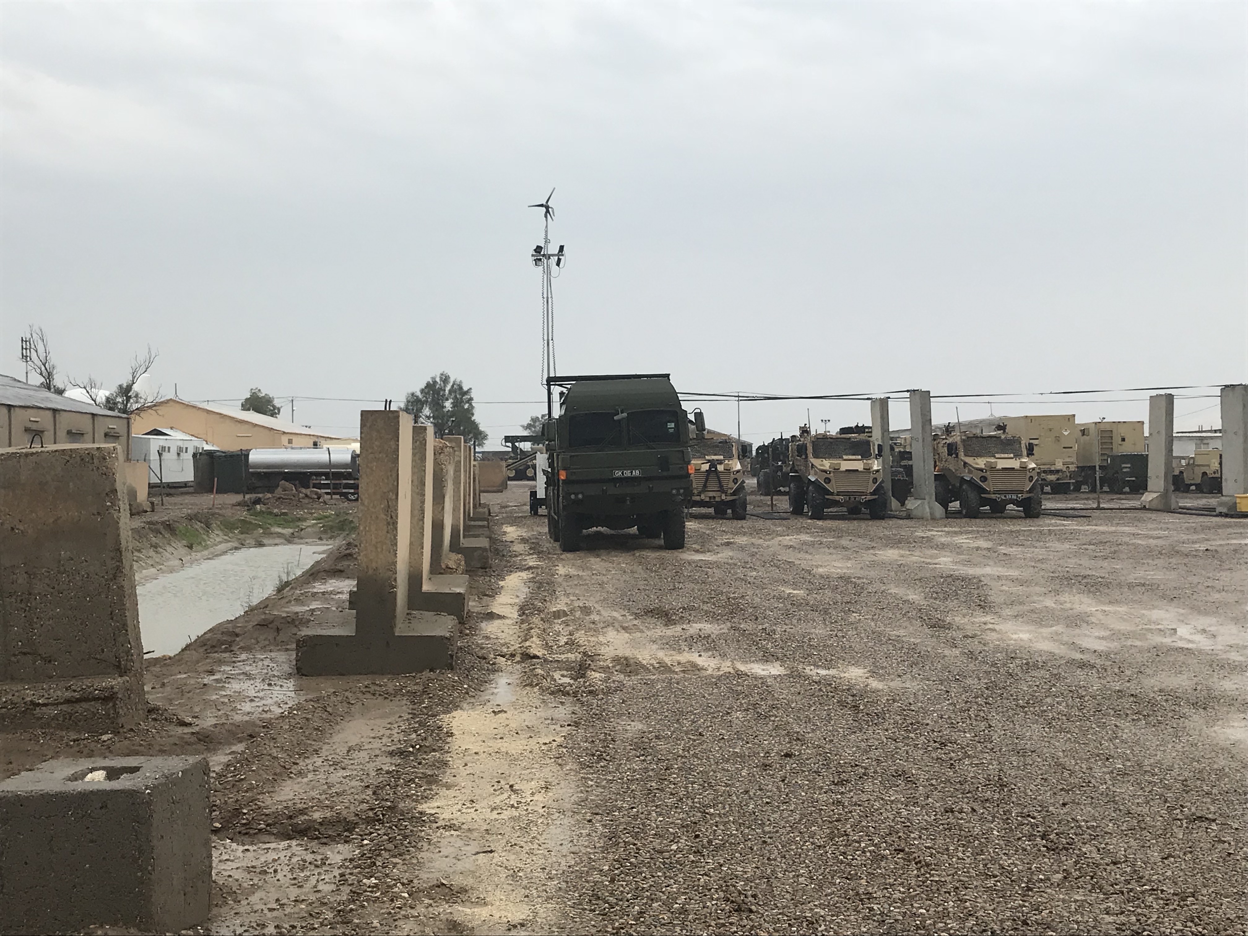
12ft, 6 ton dominoes. No end anchorage to resist anticlockwise rotation.

Some idiot tempting fate. Note the rounding of the base reduces the surface area, increasing edge stresses.
Someone, in their infinite wisdom, has decided that they want a cam net to provide shade in the car park. The net is to be draped over the top of the 12 x T-Walls which are arranged in 2 x rows of dominoes, connected to lifting eyes at the tops by ratchet straps which serve as ties. Yip, ratchet straps. There are a couple of ‘ties’ missing, but the alarm bell sounds something like ‘where are the anchor points at either end of this arrangement?’. My point being that when 1 goes, more will follow.
I sheepishly present my ‘back of an envelope’ calcs below. No ground investigation exists, but it is very obviously clay (bordering on impermeable) judging by the pools of water all over camp. I conservatively assess it to be a soft to firm clay and assume a GBC of 75 kPa (Cobb’s Structural Engineers Pocket Book p100). No wind data to hand so I’ve used a notional 1 kPa which translates to a force of 6kN acting at 2m, applying a 12kNm moment at the base.
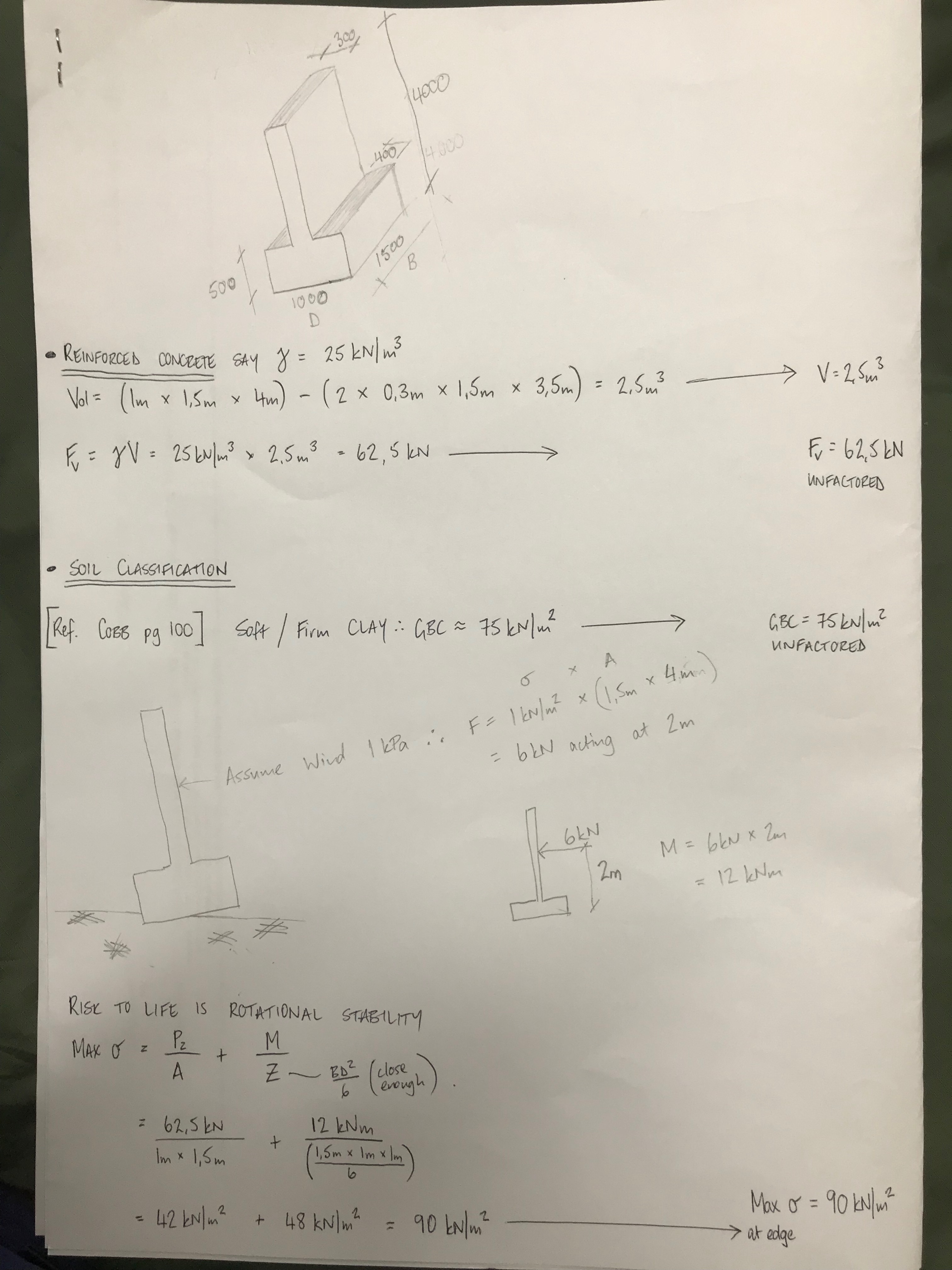

A few limitations/ assumptions (risk) in my assessment:
- I don’t actually know the shear strength of the porridge clay.
- I don’t have any wind data, made that up too.
- My section modulus is not perfect.
- I do everything conservatively because I want to prove this fails because it just looks wrong.
Feel free to rip me to shreds on the calcs. The important thing here is that there is already evidence of the T-Wall overturning so calcs aren’t actually required to raise the risk to PJHQ (although they might give me some credibility when dealing with a flat head who likes cam nets).
Nonetheless, I reckon this T-wall is going to come down like Saddam Hussein’s statue. Hope this gives you an idea of the sort of ‘stuff’ you can do to try and maintain competency when you have finished the course.

H=0.5V=Sliding Modules?!
Company tour over, I was asked to design the spread foundations (not shallow) for a two-storey temporary lecture theatre facility for Swansea University. This is as their development strategy is 3 years behind programme. Albeit indirectly thesis related, it allowed me to refresh my soil classification and foundation knowledge as well as gain some pre-phase 3 calculation and design practice.
Foundation Design
This project is to be the first installation of their new RapidPlan product – a proprietary hot rolled steel framed box of 12×3.6×3.6m. Figure 1 shows the arrangement of a module (black box running left to right) and duplicated top to bottom. It will be 50mx36m. The different colour dots denote different column loads. There will be 83 foundation pads so standardisation, like the modules, is essential for design cost reduction and ease of construction. The aim is not to use deep foundations as the other tenderers are all proposing so to be very competitive.
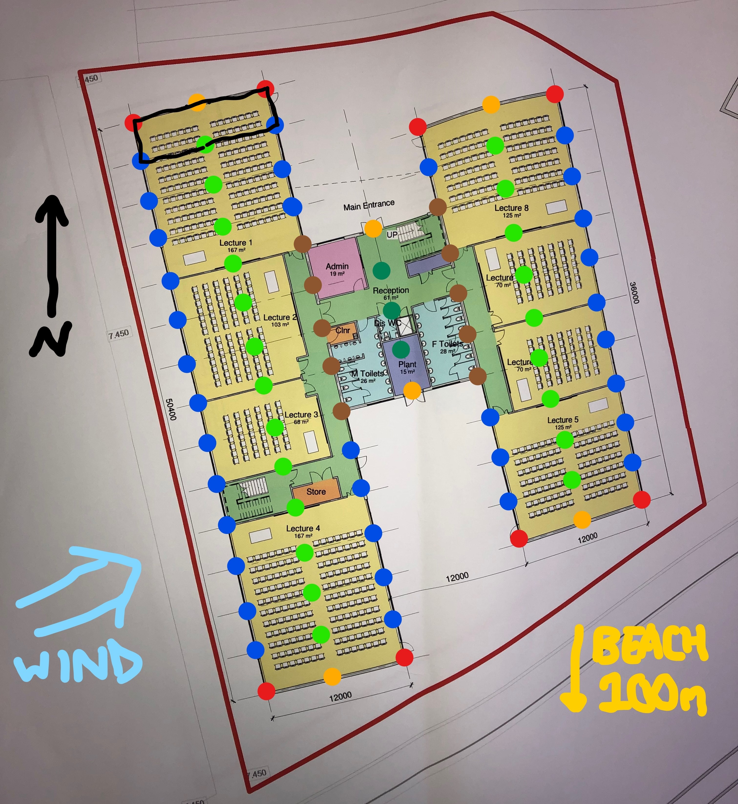
Figure 1 – Arrangement and column loads (measurements in mm)
The Site & Ground
The site is reclaimed from the sea (100m) and exposed so peak wind velocity (qp) and shape factors (cs) are high. The ground has 100mm topsoil, then a 3m engineered piling mat (with sand fill) (which is strong – Plate Load Test to 365kN/m2 with only 1.25mm settlement) then medium dense sand down to 12metres. There is loads of PLTs, boreholes, trial pit and CPT data available. The piling mat is assessed as φ’=35o and SAND at 32 o. The ground is granular so has been treated as drained and is young so normally consolidated.
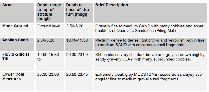
Figure 2 – Summary of Ground Conditions (WSP, 2013)
The ground water level is relatively static at 2.5m depth so is at the piling mat and sand boundary. This significantly reduces the strength of the sand (ϒ’=ϒsat– ϒdry) below that of the stiffer piling mat. Having initially used the presumed bearing capacity check (qp) from Method 2(EC7) the ground was deemed capable.
Loads
On lightweight modular structures live loads are often greater than live loads i.e. Qk>Gk. Column loads were issued by their structural engineers Fairhurst (used as a Phase 3 company before). This enabled limit state checks by Method 1. The 6no vertical loads, Figure 1, ranged from 64-440kN unfactored/service. Not a problem. However, the worst vertical to horizontal ratio at the base of the edge columns (blue dots) is 48%! I remember John saying that if H>0.1V then be worried, don’t get involved and see a specialist! Enter PET student…
Design Considerations
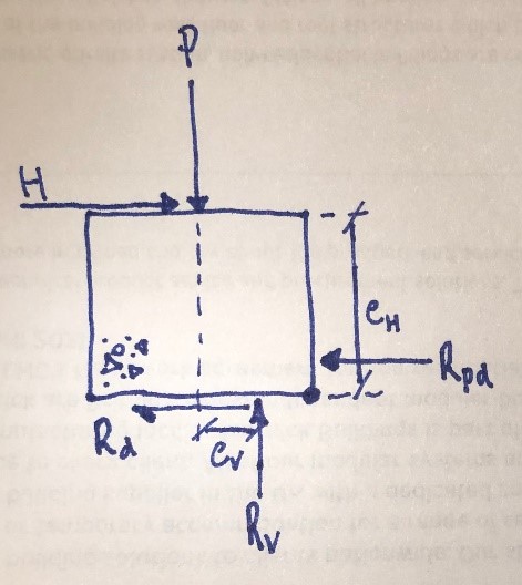
Figure 3 – Free body diagram
– A 1x1x1m concrete pad or paving slab is traditionally used to avoid using rebar and rarely with holding down bolts. A pad over strip foundation is planned because if L>B the zone of influence for bearing capacity increases from B to 3B deep.
– Each module uses moment connections (it’s a box that won’t tip over) so sliding is the module’s largest risk. Globally this means transferring 0.5H to the other longitudinal/transverse base. The column to pad connections are pinned.
– The sliding resistance (Rd only) from concrete to ground at 155kN/pad suffice compared to 64.5kN (0.5H). Passive resistance (Rpd) was not considered necessary at this stage.
Constraints
– It’s to have a 5-7year design life.
– The governing level is the FFL at the northern edge for level access. There is a 400mm level difference from northern to southern pads.
– The bases are to be at the minimum 450mm depth to prevent frost heave.
– I don’t want to go any wider or deeper than 1.5m as the saturated sand comes into play reducing GBC and increasing the risk of immediate (ρi) & differential (δ) settlement. Albeit the modules can manage 10mm.
Design Development
With the combined vertical and horizontal actions the two options considered (based on the site levels) are:
| Maximum pad thickness (1x1x1.5m) | Minimum pad thickness (1.5×1.5×0.5m) |
| + Increases surcharge load (qo) and so GBC | – Minimum surcharge load (qo) so GBC reduced |
| + Increases P with concrete self weight | – Decrease of P so GBC reduced |
| + Increases Rd and engages Rpd. | – Minimal sliding resistance (Rpd = 0) |
| – But increases moment (MH) & relies on Rpd | + Reduced moment (MH) |
| – Minimum depth of strong piling mat | + Increased depth of strong and stiff pile mat |
| – Increased concrete cost (3.4x) and installation | + Reduced installation time and cost |
| Risk is strength and settlement in the ground | Risk taken on effects of actions i.e. sliding |
Table 1 – Design options
I’ve used Geo5 to verify my ULS workings, but need to complete the SLS settlement checks which may be the determining factor. I have a preferred option and am hoping this forum will help confirm or quell my intentions. Especially as I’m still unsure about John’s H>0.1V… Any ideas? Or had similar issues? Or have I just slid you over the edge?
Realistically whilst there is an ideal engineering solution I am seeing first hand that the chosen solution is likely to be economically driven.
