Archive
Phase 2.5 & Active Buildings
I am two weeks into my self-titled Phase 2.5 – a three week attachment with a privately owned company specialising in offsite modular manufacture and construction. This is as they, Wernick Buildings, are interested in developing a rapid foundation assessment method for low-rise structures i.e. my thesis. Essentially looking at quicker ways of assessing ground bearing capacity and settlement using a Dynamic Probing Light (DPL) (EN ISO 22476-2), a small and man-handle-able SPT (Standard Penetration Test). SPT is the energy required i.e. number of measured blows (N), to penetrate 300mm with a 63.5kg mass. For DPL it is 100mm with a 10kg mass. There is currently no widely accepted method to correlate the two methods. Obviously this has both civilian and military applications, hence the interest. However, after a tour of their factory and look around their main products/modules I was taken to their latest project, the UKs first energy positive building aka…
An Active Building producing Micro Energy
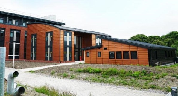
Figure 1 – ‘The Active Building Centre’s vision (centre) is to transform the UK construction and energy sectors, through the deployment of Active buildings powered by the sun, creating energy resilient communities, and significantly contributing to electric vehicle and decarbonisation targets.’
The Active Building Centre at Swansea University, is a new pan-UK university research initiative by SPECIFIC (funded by Innovate UK & EU circa £36m). It is to ‘reduce the cost and commercialise energy generation and storage components in buildings’ i.e. turn buildings into decentralised micro power stations. The ABC stored 29kWh and exported 47kWh back to the grid on the first day it was opened. This is the first building to achieve an A+ negative value on its EPC. It recycles its own energy emissions – what Building Emission Rate (BER)?! (Bld Regs Part L2A).


Figure 2 – The Active Building Centre’s live dashboard and EPC
A very apt concept when international carbon emissions are on the increase again after four years and on the first (actually second) day of the UN climate change conference COP24 in Katowice, Poland. Has Swansea secured a small chapter in the future of climate change?
True or False – Does this sit within the concept presented by Jason for his CI’s Essay on ‘energy storage in a non-fossil fuel national grid’…?
A Gantry Crane Bridge Too Far?
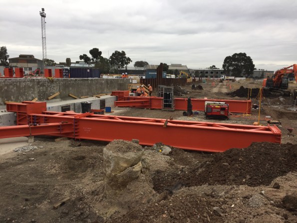
I recently had the pleasure of a week of night shift on my project (fortunately it will be my only one), during which I was responsible for overseeing the installation of the first half of a 90T beam on which a gantry crane will run to lift sections of the Tunnel Boring Machine (TBM) from the surface into the portal structure prior to launch.
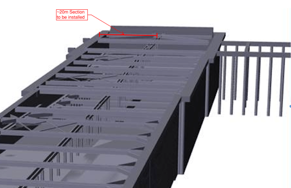
Fig 1. Highlighted gantry crane section
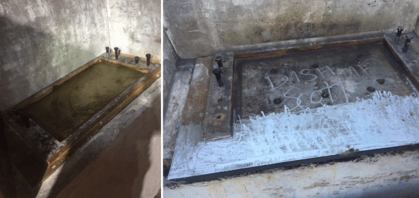
I had the night before been thrown a hospital pass and asked to install the bearing plate for the beam which sits in a recess in the capping beam, but that’s another story and it did eventually go in, see Fig. 2 below.
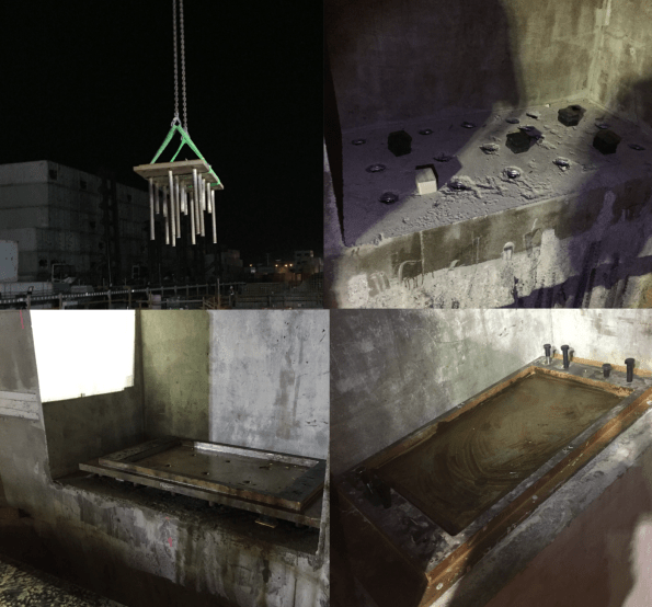
Fig 2. Installation of bearing plate
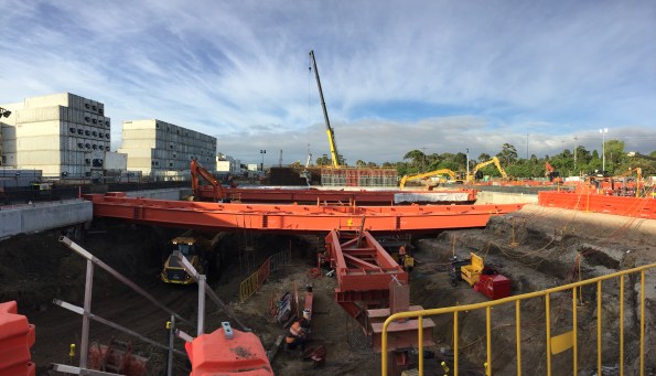
The installation of the gantry crane beam was quite simple, as you can see from the following photos, and the whole operation went quite smoothly;

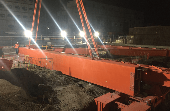
Fig. 3 Gantry crane beam install
As part of our other works the crew were also busy prepping the bearing plate on the opposite capping beam and the second section of gantry crane beam was due to be installed the following day, once our high early strength (HES) grout had gained sufficient strength. I decided to do a couple of check measurements to see exactly how the second beam would sit and to make sure we installed the bearing plate correctly. I knew from the drawings that we were looking at around 80mm of clearance from the back of the capping beam recess, but my initial tape measurements suggested it was more like 270mm. I managed to grab the surveyors before the end of their shift and they confirmed my measurements.
Having had a discussion with the foreman, and mindful that there is a risk associated with every lift, we decided to do a dummy run of installing the second beam to see exactly how it would be positioned in relation to the capping beam and the bearing plate. Having taken some photos when the beam was flush against the first section, it was evident that the “shoe” on the bottom of the gantry beam extended some 20mm beyond the edge of the capping beam, 195mm short of where it needed to sit on the bearing plate as outlined below.


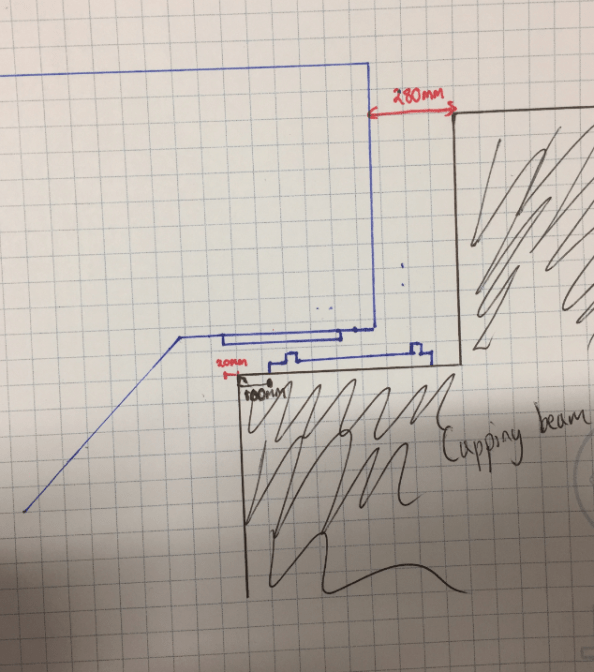
Fig 6. Location of beam in relation to capping beam recess and bearing plate
This news was not very well received in the morning and the issue appears to be the result of the the gantry beam design not being reconciled with the wider cut and cover design, though the senior project engineers are being a bit cagey with the information on this…
Clearly some remediation works is required and I suggest there might be two ways forward;
- Remediate the capping beam.
- Break back the concrete in and around the recess.
- Tie in to the reinforcement and extend the capping slightly to give enough bearing for the gantry beam.
- Fabricate an intermediate section of gantry beam.
- Install the gantry beam so that it has the necessary bearing on the existing capping beam.
- Get an intermediate section fabricated to fill the gap between beams. (a rail will run on top of the beams so potentially a ~200mm gap not too hard to bridge?)
- Get new splice plates fabricated to extend across the gap in the beams
(Note: the design of the bearing plate means that relocating the one already installed would not be sufficient to fix the problem)
My initial thoughts are that to remediate the capping beam would be too complicated with potential issues due to the fact that the load on the beam may be supported partly on a cantilever and not transferred through the capping beam directly onto the piles below.
Fabricating an intermediary section with new splice plates seems like it might be a more viable option.
Thoughts from the wider forum?
The Chosen Solution
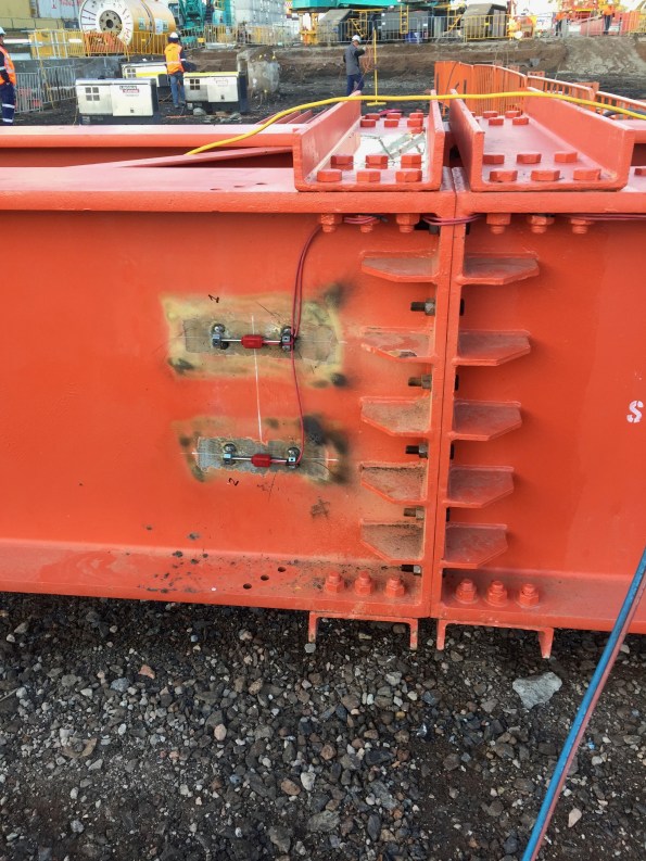
So in the end despite my cynicism, it would appear that the error in fabrication length of the gantry beam was not related to the engineering team and the blame lies with the steel fabricator in Singapore. The team did not want to draw attention to the issue so that a speedy resolution could be found on site with the upper echelons of the project wading in. It was decided that the most effective way to resolve the issue was to make changes to each of the bearing plate to allow the “boot” of the gantry beam to fit. The side already installed had fabrication work done on site , while the other was sent away to a worshop;
You’ll see from the image above that the front edge of the recessed plate was removed and an additional section of steel welded to the plate to bring it out level with the front edge of the capping beam. Both gantry beams have now been installed and at the headwall the excavation has reached level 2 of the props so waler brackets and walers beams are about to be installed. With only 2 weeks until the site closes for Christmas, the excavation will not reach base slab level as hoped but the engineering team are being driven hard to deliver. This is my last day on site, so unfortunately I won’t see level 2 going in.
Pre-setting and Jacking
I have elbowed my way into the team that have been deciding on how to ensure that the design levels will be within tolerance in the finished state and remain within the movement and tolerance specifications as per the NSSS, as well as determining how to optimise this process. This is to be done through pre-setting baseplates and connections and jacking up columns a particular stages.
Within this team, which includes BHL designers, myself and the Mace project engineer, we discussed how to cater for the uncertainties inherent in designing for movement and the change in construction methodology will impact on the pre-set strategy. The the various causes of movement considered are:
Foundation settlement
Column shortening
Elastic elongation of connections
Deflection in beams and trusses
The pre-sets resulting from column shortening are to be accommodated by adding packing plates to splice and base plate locations. Foundation settlement was accounted for by elevating the columns with base packs on the single piles and by elevating the steel comb-cap pile caps.
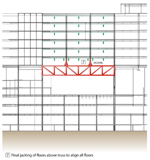
Deflection of level 5 transfer deck trusses. The original plan was:
- Install Truss with pre-camber to accommodate self-weight of frame above, SDL of frame above and cladding above.
- Construct Levels 6 and 7 (including slabs).
- Jack between transfer truss and level 6 to push levels 6 and 7 back up to level
- Construct Levels 8 and 9 (including slabs).
- Jack between transfer truss and level 6 to push levels 6, 7, 8 and 9 back up to level
- Construct Levels 10 and 11 (including slabs).
- Jack between transfer truss and level 6 to push levels 6, to 11 back up to level
This is illustrated below:


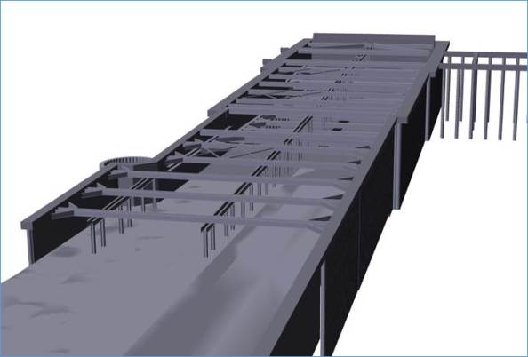
This incremental jacking aimed to avoid high stress build ups in slabs. However it is a very time consuming process so we instructed to BHL carry out further, more in depth analysis with a view to simplifying the process. This showed that the expected dead load deflection of the transfer trusses is around 20mm, which is significantly reduced from the potential movement allowed for during the preparation of their original report and which the slabs would be able to withstand. As a result we have updated the method to install pre-sets at level 5 and jacking is planned only as a mitigation measure as part of an observational method that would likely occur when slabs at all levels are installed as per image below.
A I will explain under the next title, the steel handover level at L5 will be somewhere between design level and full L5 elevated level. This value and level must be calculated to determine the handover level for level 5 and all other levels above and supported off level 5.
So we need to come up with a plan of monitoring the deflection to ensure that it is as per the designers’ expectations. To do this I will survey the levels of L5 connections before they have any load in them, i.e before steel is erected and again when fully loaded. This will show if the trusses are deflecting as expected. If movements stay within the tolerances of the levels predicted by the designer then no jacking will be required. If the movement at level is not as predicted i.e. the level 5 trusses move more or less than expected, the columns will be jacked at level 5 and lifted, once disconnected from the trusses the base shims will be added to or removed to lift or drop the structure accordingly.
Settlement due to altered construction sequence.
An alteration to the programme involved speeding up pouring of slabs at lower levels, this meant that there would be higher loads earlier on, with associated settlements, deflections and elastic shortening.
The mitigating jacking method was based on the optimised and instructed construction sequence agreed at the time the construction analysis was carried out. It was expected only two levels of slabs would be poured at the time steel erection commenced above L5. With this amount of fabric in place the designers believed that the fabricated pre-set would not have dropped significantly. This allowed us to confirm that handover levels would be level 5 design level + full pre-set. However the changes meant that the level would be somewhere between design level and level 5 elevated level at level 5 handover.
We need to know what level to build the steel to above level 5, taking account of the movement that will occur earlier than expected, in order to know if it is within tolerance. To accommodate this I have collated the as built survey levels of column base plates, and have organised a survey to take place again when all floors have been poured up to level 5. This will show the amount of settlement that has actually occurred. The steel supporting the slabs above level 5 should be set at level = design level + pre-set – actual movement below level 5.
DYNAMO MAGIC
Intro
I’ve recently started my phase three attachment with Arup in Sydney and I’m working within the structural team on the Metro Martin Place project which involves:
- demolition of existing buildings
- tunneling for new underground rail line,
- integration with existing underground rail line
- excavation for 5 underground station levels
- construction of two towers with link beneath existing structure (current Macquarie Bank HQ).
A project which Macquarie Bank offered to deliver for NSW government in return for an unsolicited proposal.


Figure 1 – Metro Martin Place Project
Structural Load Take-down
One of my first tasks has been to conduct a manual load take-down for the Northern tower in order to both; produce output which will inform design and, to verify the output of the ETABs model which will be used for further analysis.

Figure 2 – Northern Tower
Dynamo – http://dynamobim.org/learn/
As part of my load take-down I have been asked to use software called Dynamo to provide a code script which will automatically calculate tributary areas for columns on all floors (save lots of time and enables quick auto change to calcs should design/model change) by taking data from Revit, computation in Dynamo then export to excel . Currently working with another Arupian to try figure it out as it has previously been attempted but not finished. Its blowing my mind at the minute as I’ve just started looking into it – if anyone is secretly a king coder and think they can do it then there is a wham bar in it for you…..
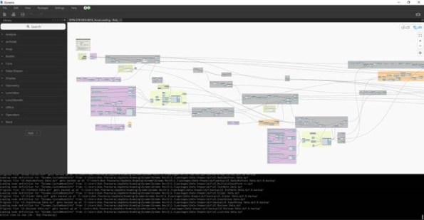
Figure 4 – Indication of current complexity of script map to compute something relatively simple
3D pdf models
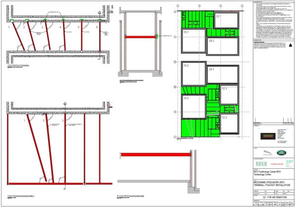
We are about to install a section of beams to support a Mezzanine floor level. The supporting structure is made from expLORe pre-cast walls (Laing O’Rourke’s own brand of twin wall). In the photo you can see the pre-formed pockets where the steel beam will bear into the 8m high wall at mid-height.
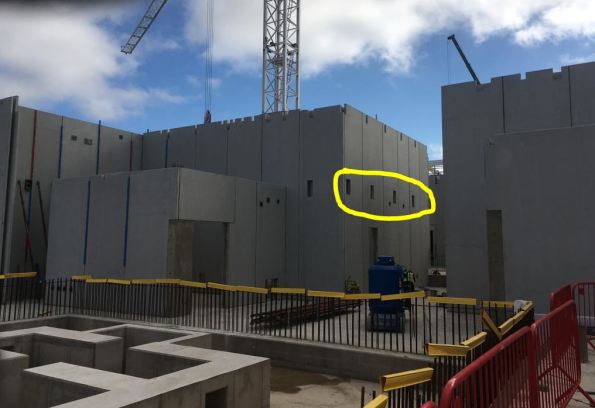
The pre-cast walls have a 16-week lead time for manufacture and so detailed installation considerations had to be made several months ago. In order to develop this, our on-site Digital Engineer modeled the installation angles the beams would need to achieve whilst on the crane hook. This check identified the need to oversize one of the pockets so beams could be ‘maneuvered’ into place.
The point of this blog is to showcase 3D pdfs. I had never seen this. Download the file on from this link.
It allows you to send 3D models to those without expensive software – an ideal method to communicate information where 2D drawings lack detail.
A very useful tool for the generalist RE when developing RAMS maybe…?
Quality – just one day a year?
On my Phase 2 at Victoria Square, Woking quality sits second on our client’s priorities after health & safety but above programme.
A lot of my time here has been spent addressing quality issues and it’s management. Having not long heard of this incentive on the project I wonder if anyone else has heard about it? And if so how our respective projects and offices across Ph 2 & 3 and the world are spending/investing in the World Quality Day?

At VSW we’re getting a presentation from the Project Manager and some light nibbles, well for the office staff anyway. Posters and graphics on the rolling screens in the welfare for the site teams… Priorities arguably a little off.
I did spot this on site however – a useful incentive to learn more than just swear words from the guys on site!

Placement in London
All,
I’m currently on the PET(C) course in phase 1. A few of us are looking for a placement in London or the South East for Phase 2. Is there anyone currently on London placements who can put us in touch with contacts for work for next year?
My email address is alastair.bramson@googlemail.com. Any help finding a placement would be gratefully appreciated.
Thanks,
Al Bramson
West Gate Tunnel Project – site update
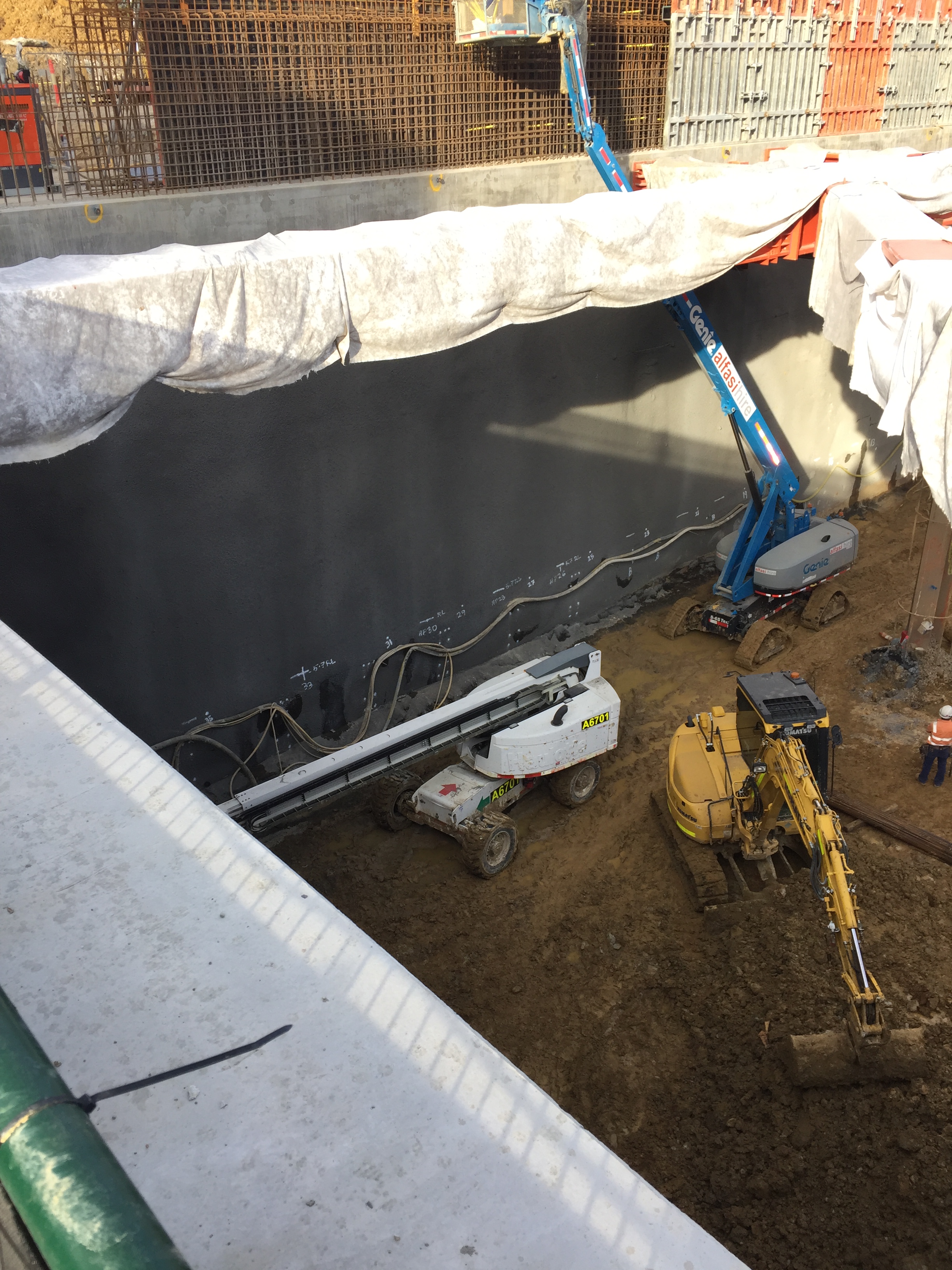
Just a quick blog to give an update on what is going on on my site at the moment as I head towards the culmination of my Ph 2 attachment.
As a reminder I am employed in the engineering team delivering the Northern Portal cut and cover structure in Melbourne from which two 16m dia TBMs will be launched early next year.
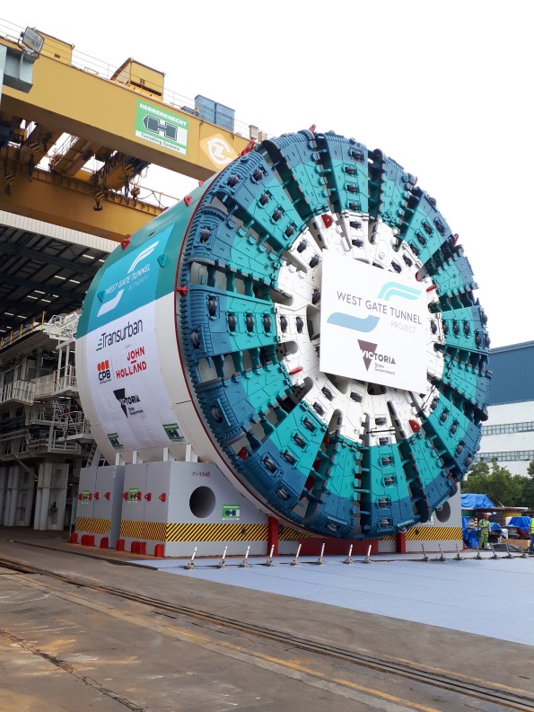
1st TBM following factory acceptance (manufactured across Europe and China)
We have finally got rid of the dirty and messy piling sub contractor on site, which has opened up some real estate and allowed the installation of the temporary propping system to begin in earnest. The planning and installation of the temporary propping system has been my primary area of responsiblity and so far we have installed five 40m props across the excavation, which has allowed us to start excavating beneath “roof level”
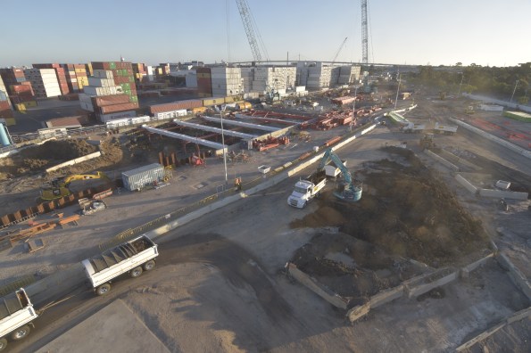 Having initially opted to use 35T excavators within the excavation, these have quickly been swapped out for 16T machines, due to slow productivity as a result of the machines getting bogged and the confined nature of the work area beneath the props.
16T excavators working beneath props
Due to hold ups in the piling works as well as changes to the design and sequencing of works (we are currently constructing using a pre-IFC design) a lot of my time is being spent managing the logistics of receiving thousands of tons of steel on site (not necessarily in quite the required order) and ensuring the sub-contractors are kept abreast of design changes and constructing to the latest design.
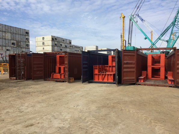
One of many deliveries arriving on site
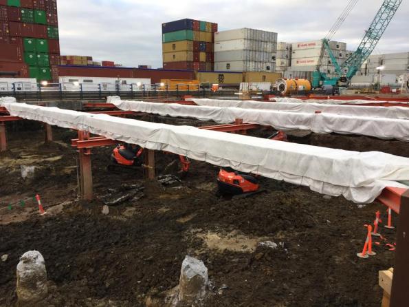
During installation of first props
During the prop installation, strain gauges are being fitted to a number of props, and settlement monitoring stations have been installed around the box, as well as prisms on the capping beam to detect any movement throughout the works.
Strain gauge installation
The data collected from these systems is monitored daily and trigger levels have been prescribed to provide alerts should unexpected movement or stresses in the props be detected. We have to submit a new permit to excavate every 24hrs which takes into account the information collected through our monitoring program.
The model below gives an indication of what the portal will look like once all three level of propping have been installed.
The TBMs are arriving in February and by that point we need to have reached full depth, poured the base slab and removed the second and third level of props, so it’s a busy run up to Christmas….
Controlling deflections in metal decks

Fig. 1 Jaguar Land Rover – Noise Vibration & Harshness Project Roof Aug 2018
Steel and concrete interfaces on my project are causing us to ‘wave’ goodbye to the specified tolerances.
For an element of multi-story steel frame, we are forming composite floor slabs from metal decking and in-situ concrete. This seemingly tried and tested method benefits from the speed of frame construction and a reduction in material costs due to combined geometric performance. And yet, even with an experienced design team and contractor, the finished levels of our slabs wave up and down by ~40mm.

Fig. 1a Heat map underside of slab defelctions
A quick google search generates lots of information and warnings relating to level tolerances for composite metal deck slabs but the outcomes we have observed seem to surprise the project team.
Is anyone else using metal decking or aware ways to overcome problems with its use?
1. Tolerances
A regular 6m x 7m grid of columns supports a typical arrangement of primary and secondary beams.
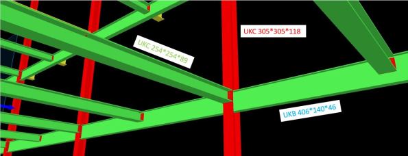
Fig. 2 Screen grab of model with slab removed
Table 1 – Steel Frame Elements
| Element | Size |
| Column | UKC305*305*118 |
| Primary Beam | UKB406*140*46 |
| Secondary Beam | UKC254*254*89 |
| Metal Deck | ComFlor 51+ |
The designer produced a tolerance specification, in which they confirmed deflections should not exceed the lesser of span/180 or 20mm (in accordance with UK National Annex to BS EN 1994-1-1 and BS5950-4).
In our frame; 7000 / 180 = 38.8mm > 20mm therefore max δ = 20mm.
As built surveys confirmed that the secondary beams (UKC254) were consistently deflecting ~20mm under construction loads only. This was also true of the primary beams (UKB406).
The greatest deflection is highlighted by the sketch in Fig. 3 and occurs when the secondary is connected to the primary at mid-span. The 20mm tolerance has already been used up and the subsequent deflection in the secondary means the combined deflection at mid-point of the slab is ~40mm.
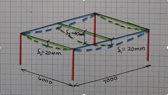
Fig. 3 Steel frame bay deflections
2. Method
The concrete pour on Level 1 was poured to a level. An inexperienced graduate engineer was convinced by a construction manager that this was the correct methodology. All drawings indicated that slabs on metal decking should be poured to a thickness to prevent ponding of concrete.
As more concrete was poured to achieve the correct level, the deflection increased under the additional self-weight loading. This cycle continued and resulted in a slab 40mm thicker than design at mid-span.
We felt this error in methodology was the root cause of the excessive deflection. For Level 2, particular attention was applied to ensure the slab was poured to a thickness and yet similar deflections were observed (Fig. 4).
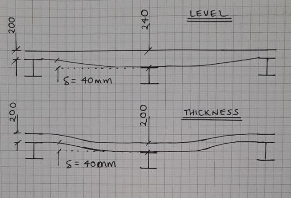
Fig. 4 Slab profiles
3. Future options to limit deflection
This had led me to believe that the sections have been under sized in the design. The slab on Level 2 is due to be a plant room and has gullies positioned adjacent to columns – if any of the plant leaks, water will not run uphill on our wavy slab!

Fig. 5 Finished level variation in slab pour to thickness
In a report by the ASCE[1], four options to reduce deflection in composite metal decks are offered;
- Increase section sizes
- Pre-camber members
- Place additional concrete
- Back propping
Given that our frame is already built, the only option I think we have is to install temporary works to back prop future slab pours.
I welcome any other suggestions…
Will we also need to increase the reinforcement in the slab?
Should we allow for more deflection once variable loads are applied?
______________________________________________________________________________________
Updated to show more recent as-built heat map of finished level of slab.
Majority of LHS was poured to a level with clear results +/-9mm.
RHS and bottom left all poured to thickness with -40mm under secondary beams.
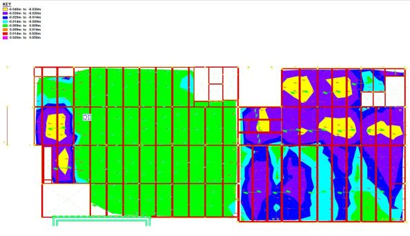
Fig. 6 As-built finished levels
[1] https://www.concreteconstruction.net/_view-object?id=00000153-8c44-dbf3-a177-9c7d96b40000
Loads of Temporary Steel
Introduction:
This seems like a relatively unique engineering feat so thought worth a quick blog to share how I think it works and highlight an issue which will soon need addressing.
The original Shell House structure is being renovated. The clock tower and three sides of the facade stay, everything else goes. Also, an additional 4 storeys are excavated prior to building back up.
Image 1. Original Shell house structure
Retention works prior to demolition:
- Plunge columns
- Crane base
- Stability core
- Perimeter transfer structure
- Clocktower transfer and support elements
Retention works during Demolition:
- Façade support braces inserted as demolition progresses
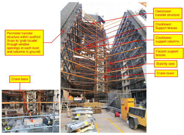
Image 2. Facade retention system as at 24 Aug 18
How I think it works:
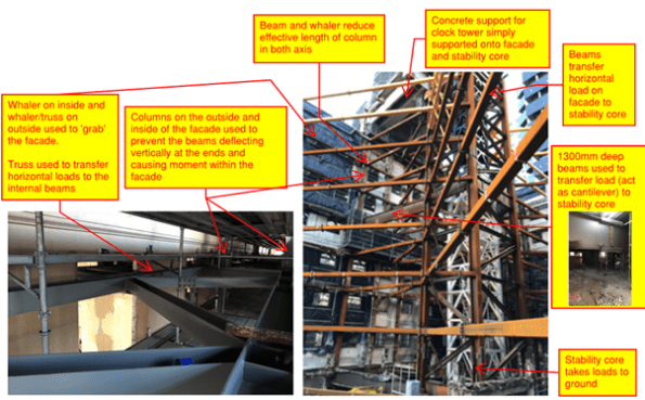

Image 3. How I think it works
Retention works during excavation (soon to commence):

Image 4. Excavation procedure
Issue:
Plunge columns are up to 40mm out of plumb – what are the risks, how can they be mitigated?
I hope to answer these questions in my next TMR so any comments very welcome
