Archive
Rules of Supervision
During Phase 1 we learned of two rules of supervision (Civs; you may or may not have been party to this information, if not, it’s your lucky day).
I forget the order, but they are:
- “It doesn’t matter what you say, people will do whatever the f**k they want.” Phil Moffitt, 2016
- “Good to trust, better to check.” Fisho Fisher, 2016
Recently I was reminded of these valuable lessons.
Me: “Lads, I’ve got some tarpaulins for the dampers, can you take them up and see if you can fit them please? The eastbound damper will probably need tying down? Do you have any rope?”
Nacho the Labourer: “Yes, I think we have rope.”
Me: “OK good, do you have enough? Let me know if you need more and I’ll find some”.

Later I asked Nacho if he had completed the task. He said “Yes. And I am confident I got the right place”. Can’t argue.
A Yorkshireman in Sydney…
I will start with a confession: Not one for Facebook, Twitter, Instagram, or any other real interaction with Social Media, this is pretty much the first ‘proper’ blog of my life. (Although I suspect most are not interested in that fact and want to read on!)
Down-to-business, and following on from a string of “I do this on site” type blogs, I invite fellow bloggers, backseat readers and academic staff alike to read my submission.
Following in the footsteps’ of James Grant, I have found myself (not literally) employed as a Services Engineer on a hospital redevelopment project nearing its end. The Project is summarised as:
PROJECT
St George Hospital Redevelopment. (Stage 2 of 5.)

CLIENT
New South Wales Government, represented by Health Infrastructure.
MAIN CONTRACTOR
Multiplex, part of Brookfield Asset Management (Portfolio worth $260bn).
LOCATION
16 km directly south of Sydney’s Central Business District. (Think Opera House and the Harbour Bridge area of Sydney.)

DELIVERABLES
An 8-floor Acute Services Building; an extended car park (from 7 to 8 levels); an MRI unit; and, the refurbishment of the hospital’s existing Tower Ward Block.
PROJECT VALUE
$170m, of which $80m is assigned for Services.
CONTRACT TYPE
Known as a “GC 21”. Works are conducted under a Design & Build arrangement and the contract is comparable to that of the NEC 3.
CONTRACT RISK
A “fit-for-purpose” clause leaves much open for debate between Stakeholders. Despite User Group Workshops, differing perceptions of what this clause entails leads to time-consuming meetings and potentially costly outcomes.
RESPONSIBILITIES
According to the Project Management Plan’s description of my role, I am responsible for the management of all aspects of electrical, mechanical, hydraulic, fire, security and lift services design, coordination, and installation, completion, commissioning and training for the project. This includes quality control, negotiation with subcontractors and obtaining approval as well as liaison with the Client, Architect, Consultant, Subcontractors, Construction Team and the User.
REALITY CHECK
Although my job description is quite clear, the initial reality of my responsibility has been different. Understandably stuck somewhere between a Graduate Engineer and Site Engineer in the minds’ of others, I have had to reinforce why I am on site, what I am trying to achieve, and how I should achieve it. Effective communication is proving critical; time is at a premium from those that I am seeking help from.
Beyond the observations listed above, I am intrigued at just how complex applying Design Philosophy in Construction can be. Focusing on St George Hospital as an example, from its inception of an 8-bed ward cottage hospital, constructed in 1894, it now has approximately 550 beds, 2500 staff, serving 250,000 district residents. More than 45,000 admissions and 723,000 outpatients are administered each year. The last iteration to the hospital’s expansion, a previous redevelopment project, was conducted in 1980 costing Aus. $200,000,000, designed to last 50 years. The problem is the fundamentally the same – population modelling. To compound matters, construction constraints on the site are increasing – building more on a live hospital site, with less space, more traffic and, increasing competitiveness for resources. The space available to off-load resources for the entire site is constrained to 825m², approximately 1/7th of a football pitch.
Future proofing designs is a difficult art. In my opinion, it is the resilience to change. To achieve this, one must look beyond life-cycle costing and focus more on whole-life value; a philosophy difficult to sell in business cases which focus on value-for-money for a specific budget year.
Away from trying to understand more about Construction, and despite bags of encouragement from my new work colleagues, who have rather ingeniously given me an Australia nickname – Fisho – I still drink Yorkshire Tea, not oodles of coffee. (Although, if I had my time again, I would open a coffee shop in Sydney. #moneyprinting)
Until next time,
Fisho
Safety Concern Over Temporary Works
As Project Engineer I have been overseeing the pile installation, pile breakback and enabling works prior to the FRP (form, reo, pour) contract on the two abutments and central pier for the Canal Bridge, sharing the work load with my partner from the Royal Australian Engineers (RAE).
Abutment A is situated between a high pressure gas main & sewer to its east, and 6 lane carriageway to its west, excavation has therefore been relatively complex to say the least.
After taking an academic day, I returned to site to quality assure the on going excavation. A temporary works designer had supplied details on the installation of a UC shoring system to support the gas main while excavation took place for Abutment A (the gas main is marked by white vertical conduits in the photo). Emanon (sheet driving subcontractor) had driven UC’s into the ground, ready for sleepers to be inserted between them as the excavation progressed. While away though the Site Foreman and Site Superintendent had decided the shoring needed to be extended (see photo below).
 Figure 1 – Abutment A Excavation, Canal Bridge
Rather than reactivating Emanon to install further UC’s, they used a discarded railway line and used an excavator to drive it into the ground. There were a number of issues with this;
- The railway line did not have the same local geometry as the UC’s;
- The correct toe depth was not achieved;
- Previous impact or damage to the railway line was not known;
- A verification of the revised temporary design was not signed off;
- A Senior Project Engineer had not signed off on the approved installation method of the temporary works.
I therefore closed the excavation and had it backfilled until the design could be approved or verification rectified the design. This was to the annoyance of the foreman and superintendent with the usual retort of, “but we’ve always done it this way”.
I took measurements of the local geometry of the railway line and instructed our temporary works designer to calculate the suitability. The soil properties were extracted from the GI and assumptions had to be made on the yield strength of the railway line (200 MPa). Brom’s method for laterally loaded piles was used and considered both short and long pile failure modes. A FOS of 2 was implemented in the verification. The design was then verified by a second temporary works designer, once complete the excavation could be reopened.
If you were wondering, the state of the reo cage in the pile in the foreground has had an NCR raised against it as the piling subcontractor forced it into the CFA pile using an excavator bucket rather than vibrating it into place.
How much reinforcement is too much reinforcement?
I draw your attention to the photos below as an illustration of the problem. It shows the quantity of steel being installed both longitudinal and transverse.

Photo 1 – B40 Longitudinal Bar (The steel coming towards the photo is the bottom longitudinal steel at the end of a beam)

Photo 2 – Transverse Reinforcement

These beams are at the B01 level in the Battersea Station Box, in places 3.8m deep, acting as transfer beams for the over site development. They have been designed for point loads of up to 10MN, transferring the load to plunge columns.
If I now break this into two:
Longitudinal steel – The quantity of longitudinal steel in places is greater than the 0.04Ac. I thought this 4% figure existed to prevent brittle failure and allowed tension cracks to appear in the concrete prior to the beam failing. Therefore, if this is the case then what are the implications of a design such as this?
Transverse steel – Looking in the guidance for the minimum spacing of transverse steel, the distance should be 20mm (10mm aggregate) to form a bond between bars. Clearly this does not, therefore I see three problems potentially arising. Firstly a proper bond will not be able to form between traverse bars; does anyone know what implication this will cause? Does it mean a reduction in shear resistance? Secondly it does not allow for vibrating pokers to be lowered into the concrete at this location during casting and thirdly it acts as a sieve during pouring, causing separation in the concrete. All of which are mentioned in the codes when designing transverse steel.
Looking into the detailing a bit further I discovered in the IStrutE detailing guide, the table below shows the difference between size and diameter of bars. Apparently one should not confuse size with diameter, after all a size 40mm bar is 46mm in diameter. Therefore when this transverse steel was detailed, if the size was assumed to be the diameter, all those millimetres add up to the situation in the photos above.

Service clash and visualising drawings.
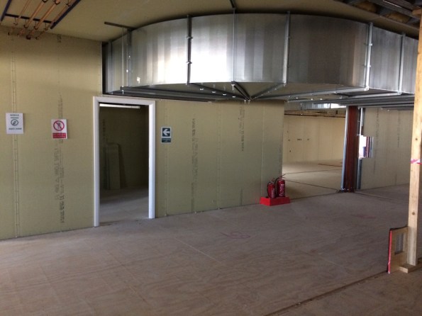
The East Office at Hinkley Point is a 13,000sqm building formed of 12m x 3.6m x 3m modules. Currently undergoing first fix services it is the furthest along of three similar structures on site – it is not yet water tight but that is a different issue.
This post is just to quickly share the issues that have been experienced on my area of the site regarding service clashes, particularly drainage.
A 3D model was constructed for the building – clash detection was said to be acceptable. Foundations were constructed by another contractor on a contract with the Principal Contractor. The modular building contractor approved the as built strip founds by survey prior to beginning install of the modules stating that the greatest disparity in the service pop ups was +/- 40mm.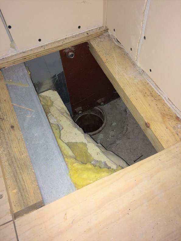
The intent was for vertical soil stacks to connect directly into the waste pipes from WCs in the corners of each unit. This did not account for the steel plate in the corner of every unit to allow attachment of plasterboard or for certain units to have their beams sit directly on top of the service pop ups. I advised (as PC we can’t do anything else) that they cut holes in the plate, as they were going to install a series of flume like bends which would mean additional boxing in. It also meant the plumbing sub contractor taking on risk from straying from the design which was unfair on his part.
Also, I think John mentioned always to check cross-sections rather than just look at plans. I have seen this first hand as a kitchen extraction duct is being installed that allows only 2.2m headroom, not including a floating ceiling to be installed. The spin off from this is that if this duct is not changed it creates a ceiling void above 800mm depth, thereby requiring fire detection or sprinklers. The duct also (as everyone who has seen it agrees) looks odd. Which has been enough to get the designers down to have a look this week. The duct is extraction for a reheat kitchen, yet it is twice the size of the same piece of kit for a proper kitchen in an adjacent building. Maybe a spec issue or stray decimal point.
The M&E, although not what I wanted to be involved in, has been an education in project life cycle and the importance of understanding what drainage goes where prior to casting concrete, signing off surveys, properly visualising the end result of an asset or committing to a design in the case of the extraction ductwork. With time pressure it is not as easy to be as thorough in some areas viewed as less critical but it is often the details that cause bigger problems from what I have seen over the past 7 weeks.
Hoping to get mud on my boots soon or at least within touching distance of a bit of plant (within the safe zone, having filled out the requisite forms etc).
Thoughts on over excavation of a contiguous pile retaining wall…
I’m currently looking at the implications of over excavation on the basement (passive) side of a contiguous piled retaining wall. Whilst onsite I became aware that the sub-contractor responsible for the basement reduced dig had moved beyond a hold point before another sub contractor had completed the temporary reduced level on the retained (active) side. The reasons for this are numerous but boil down to poor communication and management of the required design construction sequence. Figure 1 below is a sketch of the wall cross section during final construction and temporary cantilever states in accordance with the design checks conducted.
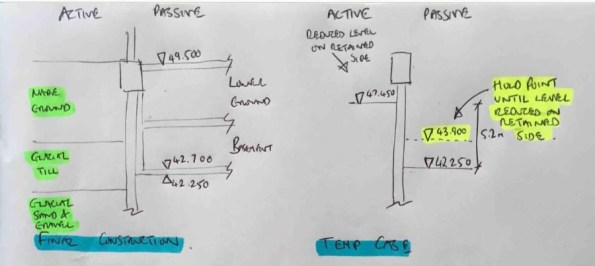
Figure 1 – Final construction and temporary construction stages
In order to understand the impact of this error I wanted to analyse the impact of the worst case (figure 2) where the full passive excavation had been completed and no excavation had occurred on the active side. Note that fortunately work was stopped on site prior to this case occurring!

Figure 2 – Worst case if construction sequence followed incorrectly
The initial WALLUP retaining wall analysis (step 1) gave a minimum pile length for stability of 12m from pile platform level (PPL) to the toe at 39.1mOD. Re-analysis for the worst case shown above caused an increase in the max BM, shear and displacement of the wall in SLS conditions and a failure in ULS conditions due to passive failure. This would be a simple conclusion if the wall had been constructed to the 12m length from the original retaining wall design. However, the contiguous wall is also required to support an axial load for the planned structure above. The initial analysis of axial capacity (step 2) lead to a minimum pile depth for axial compression of 28.5mOD and a pile length of 20.6m from PPL. This design was based on resistance provided in skin friction below formation level and a minimum rock socket of 1.5m. Note however that the initial structural reinforcement design (step 3) only extends to the depth calculated for stability (in step 1) and was based on the maximum moments and shear from this calculation. The image below summarises the initial pile design results.
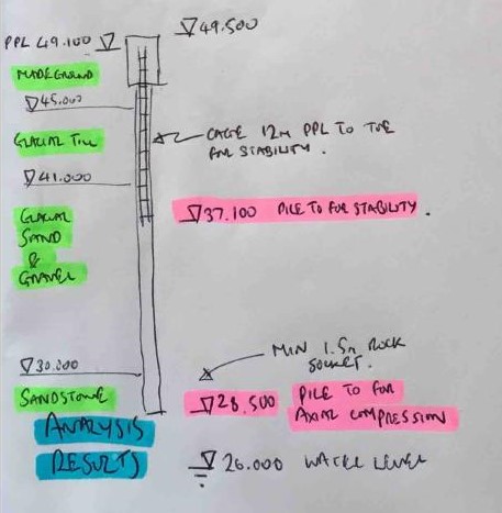
Figure 3 – Initial design analysis results
So, drawing conclusions now on the effect of the over excavation shown in figure 2 becomes slightly more difficult. My initial thoughts are:
1. The passive failure issue is now removed due to the increase in pile depth.
2. There is still an increase in BM and shear force that would mean the structural reinforcement would be under designed and could lead to an STR failure.
3. The structural reinforcement should extend down to the new pile toe depth for stability.
4. There would be an increase in deflection of the wall which could lead to other issues including eccentric loading in the final permanent state.
I’d welcome any comments or thoughts on the above logic or any conclusions I may have missed.
Any Site Managers on Phase 2?
For anyone that thinks they sound like a dick when they tell someone to move something that’s not stored in the right place:
http://www.bbc.co.uk/news/uk-england-london-39816357
Online CPD – ICE CPR presentations
Whilst searching through the ICE events page looking for CPD events in the Manchester area I was presented with only 2 search results, a Fellowship workshop and a student pub quiz. Acknowledging that I may not be quite ready for the first and questioning the output I would get from the second, I widened my search to see what past lecture recordings were online.
It was then that I found a recording of the James Rennie medal final for 2017 (link here). As detailed on the ICE website, “The James Rennie Medal recognises the best Chartered Professional Review candidate of the year. This year’s final will feature ICE’s top three Chartered Professional Review (CPR) candidates of 2016. They will each present and defend their CPR reports to an audience.”
I found it a useful insight to CPR presentations, even if it is currently a year or so off. Hopefully it’s of use to others out there if you weren’t already aware.
SUPERLATCH – An innovation in piling safety and a time saver
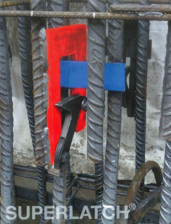
Figure 1: Superlatch connection system.
Today I used SUPERLATCH to splice the pile reinforcement cages for the first time, and I thought that the overall system is interesting and worthy of a blog. The inventor (Steve Render) was here as the system is in its infancy, so I had a good opportunity to ask a few questions and to get a brochure from him as well.
Superlatch is a highly efficient means of connecting spliced reinforcement cages during the construction of rotary bored piles, and I was assured that it can be used in CFA and diaphragm walls too. It has two main aims, to save time, and to increase safety. I will cover these separately below:
Safety
Traditionally the connections between sections of reinforcement cage have consisted of multiple shackles or u-bolts which are secured by the contractor between the piles. This practice requires that the operatives reach through the gaps in the cages with their hands or even whole arms, whilst the lower cages are suspended on the casing with temporary supports, and the top cage is suspended by a crane. Although this process has been used at BPS for all piles so far without incident, if either of these cages were to move, the arm / hand would be at serious risk. Superlatch is welded to the cage off-site during cage construction, and when the cages are lowered onto the preceding cage, the latch mechanism (covered later) automatically secures the connection with no need for any operatives to reach through the cage. If the cage needs to be dismantled for any reason, there is a release tool (Figure 2) which again does not require an operative to reach through the cage.

Figure 2: Release Tool
Time
In theory, not having to manually splice the cages clearly saves time, however so far my experience of Superlatch (one pile consisting of 5 cages and 4 splices) is that it is slower, although I am confident that it will soon speed up. The cages which it is being used to splice are formed of 44no 40mm diameter bars, spaced equally in pairs. There pairs are welded together in places, the uppermost of which is approximately 1.2m from the end. This results in some pairs having gaps between them at the end, as shown in Figure 3.
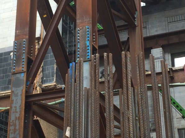
Figure 3: Gaps in paired bars.
When lowered, the Superlatch in the upper cage sticks into the lower cage like a fin, as seen in Figure 4. These fins need to be located between the pairs of bars, but it has proved difficult to achieve this, often resulting in many lowers and raises of the cage before it is in the correct position. I have suggested that the pairs of bars are spot welded at the top to mitigate this problem – but no welding of the cages is allowed on site, and attempts with tie wires proved insufficient. The fabricator will be contacted and asked to do this weld at the top, which should improve the time taken on piles where the cages are yet to be delivered. Clearly this will not be an issue when single bars are used. I expect this system to save approximately 10-15 minutes per splice in the near future, resulting in a considerable saving of 40-60 minutes per pile, as well as increasing safety.

Figure 4: Multiple latches per splice protrude like fins into the inside of the cage.
How does it work?

Figure 5: Superlatch Mechanism.

Figure 6: Mechanism in position.
As can be seen in Figure 5 and Figure 6, Superlatch works with a simple spring loaded latch, which is lowered onto a receiving band (shown in yellow on Figure 7) on the cage below. This bands can be substituted with a plate for a diaphragm wall. There must be a minimum of 2 latches per splice, today we had 3 for the lowest splice and 4 for the remainder, due to the load each splice would carry increasing up the length of the cage (the cages are suspended during the pour.) A range of sizes of Superlatch are available, with an individual load range of 1-6 tonne, so it can be suitable and efficient for small to large cages.
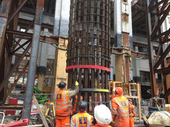
Figure 7: Lowering the cages together.
Conclusion
This system is undoubtedly safer, but in my experience of piling (admittedly limited to just 7 weeks) the risk which it mitigates has a very low likelihood already, and potentially does not need further mitigation. However, as a time saving product, I think that it is a really good option. Bauer and their cage fabricators have not used Superlatch before, and the operatives here and the fabricators at the yard are still learning the initial lessons of how to adapt their techniques and designs to maximise the potential benefits. With a little more experience in splicing cages in this way, coupled with an extra / repositioned weld when bars are in pairs, I think that the product will be a success.
I have added the Superlatch brochure here if anyone is interested, and I will reply in 1 to 2 weeks with an updated opinion of time savings once I have used it more and when the modified cages arrive.
Ground Water and Retaining Wall
This is one for those of you with a keen eye for geotechnics I think.
I am currently looking at getting all the ducks in order and the sequence of the bulk dig on One Nine Elms. Prior to the excavation, a ground water pumping test will check that the basement box is water tight (more likely reduce the risk it leaks like a sieve). This has raised a slight contractural issue which has been missed in the scope of works and allowances the sub contractor has agreed.
The design of the D Wall assumes the ground water level at the level of the soil on the passive side throughout the excavation. However the pumping test contractor has not allowed for recharging the box after the test and the substructure contractor have specifically stated their rates for excavation assume the ground water level is below formation.
During a planning meeting I was quizzed fairly robustly, below I have summed up my response. Are my comments sensible or have I been an idiot?
1. Why would the sub contractor specify the GW level in their rates? If the GW level is at the surface, the excavated soil will be wet. Dry material will need to be imported and mixed with the wet before it can be transported and accepted at the tip, therefore resulting in cost. I also suspect bulking factor is dependant material and water content.
2. Would a lower GW effect the working surface? Yes it would improve it, effective stress goes up which is directly proportional the the shear strength of the soil.
3. Why would the wall be design like that, it’s not how it is constructed? It’s the worst case, the designer may have been unsure of the methodology so will have taken worst case GW and therefore higher pore pressure.
4. What would happen to the D Wall if the GW level was below formation during the dig? Errmmm….. it would effect the wall stability. See scribbles below, in short passive pressure would increase, therefore stability would be better.
 In terms of the strength, the SF & BM capacity of the wall won’t change as the strength of the steel and concrete is unchanged but the loads exerted on the wall will. I suspect the position of the max BM will change but be lower in value. Running it through software would have quickly told me this but there was none to hand and I didn’t fancy getting my pencil out, plus I would need to check at the various excavation stages. So my answer was weak in this regard.
The wall carries a vertical load, this can essentially be modelled at a pile with some of the shaft resistance gone i.e. where it is excavated. The wall will experience the max vertical load in the long term therefore it would be safe to say the construction methodology will not effect the vertical capacity.
Multiplex being a management contractor the would never rely on my advice, even if I put numbers behind it. In the end the design contractor will be paid to alter the GW level in their software and give the thumbs up. A 10 min job charge at a day or two fees.
