Archive
Tumble Down The Rabbit Hole
My site is increasing the capacity of a Wastewater Treatment Works (WwTW) near Rochdale to cope with the growing population and to prevent occurrences of discharging untreated waste into the local Brook, (surprisingly common with 126 recorded spills from this site alone since 2020). The site consists of multiple new reinforced concrete (RC) structures that have required numerous cofferdams in order to install pipework and build the foundations for the various treatment tanks.
The ground investigation (GI) was sufficient enough to understand the basic risks in the ground. Firstly, the site has a risk of contamination given its use, the borehole log records a summer ground water table located approximately 2m down and the lithology is principally soft sand, overlaying very soft sand. This indicates that with the excavations varying in depth between 3-6m the risk of water ingress must be addressed.
As with many projects, the principal driver on the site is cost. Pressures on management across all parties is evident. They need to keep costs as low as possible as the project is significantly in the red (the principle contractor is circa £5 million for this site and around £20 million across the £150 million works package with estimates of the figure growing to £40 million). However, this pressure is resulting in repeating mistakes, losing time and incurring further costs.
It seems at times the management are in a fantasy world like Alice in Wonderland where they are requesting and accepting Temporary Works Designs (TWD) without careful evaluation, in the hope that somehow the conditions have significantly improved. The designs address the requirement for dewatering, stating it is the clients responsibility to reduce the ground water level below formation level prior to starting to excavate. Additionally, it identifies ‘fine ingress’, saying the client is to ensure suitable control measures are in place to reduce and to monitor existing structures due to loss of fines given the granular nature of the soil.
As the purpose of the cofferdam is to have people working inside it, it must principally be safe. But secondly, the cofferdam needs to remain dry enough to enable the works to be completed. Knowing the the ground has high permeability the decision to install ‘open’ cofferdams that are not sealed the whole way round, and in the most recent case with sheets without clutches is questionable. Dewatering systems were installed to draw down the water table, but seems to be designed in isolation, with little link between that and the cofferdam design.
As a result of the open coffer design in coarse grain soil with high permeability within the ground water table, each cofferdam has flooded and sink holes have formed due to fine migration between the sheets. Understandably, the cost of a ‘closed’ cofferdam is greater, however, the pressures to reduce losses and minimise costs are overshadowing the benefits of saving time and cost by preventing flooding and the risk to personnel of sink holes injuring them or destabilising other nearby structures.
Has anyone else found the commercial pressures are further increasing problems?


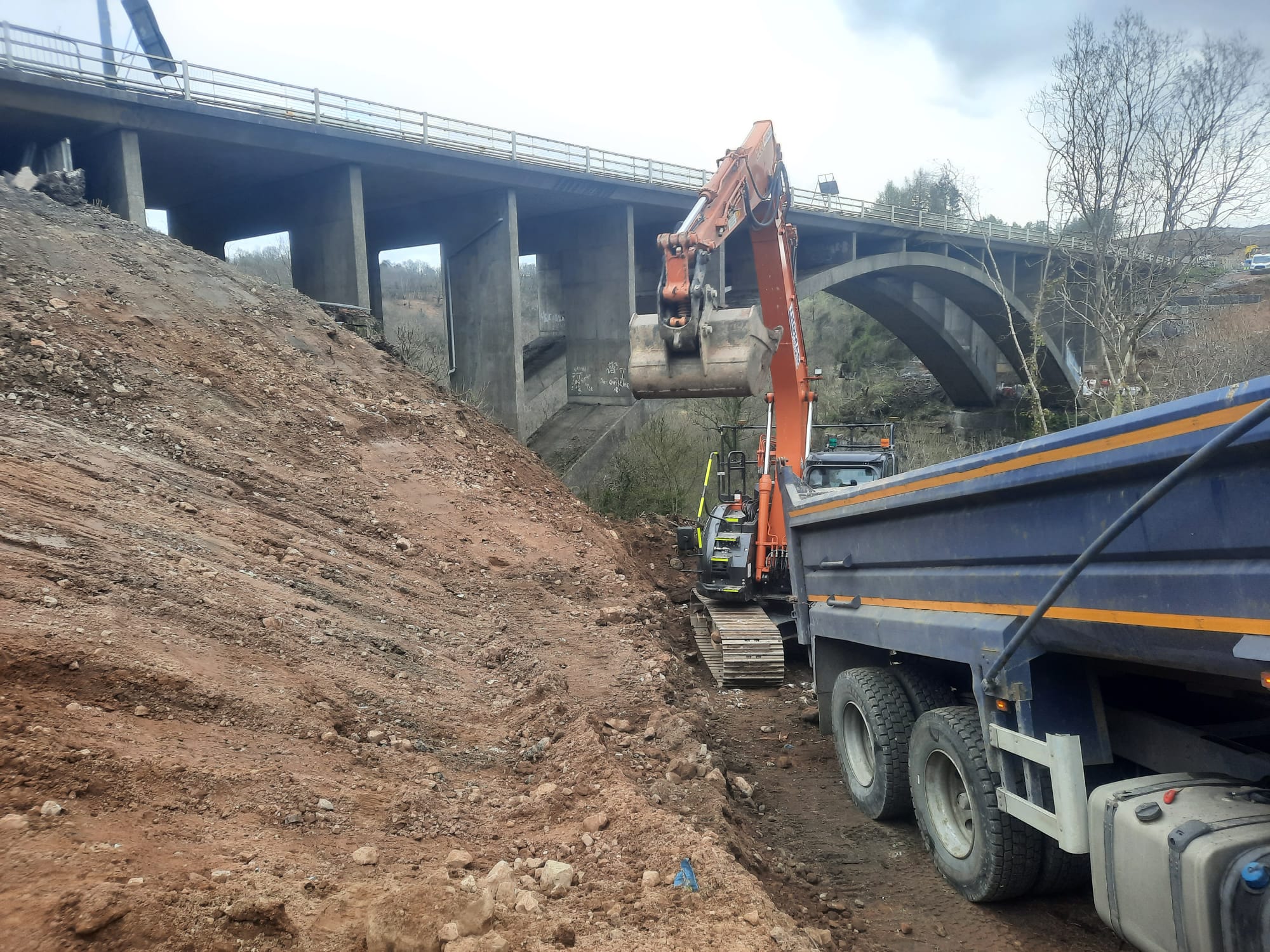
Design & Build – or Build, Design & Re-build?
The project I’m working on is using a ‘Mutual-Investment-Model’ (MIM) form of contract, which is a Welsh Government type of Private-Public-Partnership (PPP). As such a special purpose vehicle (SPV) (Known as Future Valleys Construction – FVC) has been formed with the main contractor (FCC) and designer (Atkins) both being part of Future Valleys Construction and operating a ‘design & build’ system to deliver the project. The Welsh Government has a minor equity stake in FVC and so any profits are in part shared between the Private and Public participants in the contract.
A key benefit of Design & Build contracts is that they allow for works to begin rapidly – in theory this should reduce the overall project duration, reducing cost, as design can keep pace with construction and issues be resolved as they materialise or are realised on site. In addition, from a client point of view the risk lies with the main contractor as a price is usually agreed up front for the delivery of the project – in the case of the A465 widening this is set at £590m.
Across the A465 widening scheme, and in particular on my site works are beginning before ‘for construction’ drawings have been issued and designs finalised. Work is being done using ‘for information drawings’. I have been told that this is to save time and allow the overall programme to be accelerated. However, I have come to question this logic.
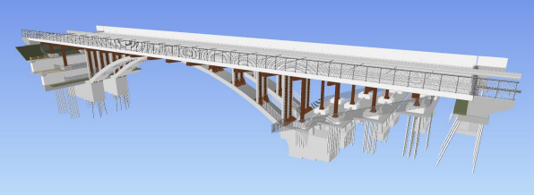
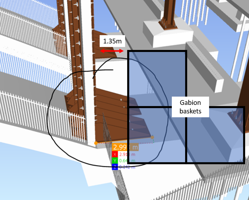
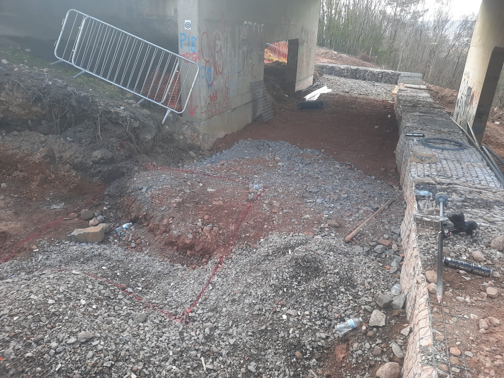
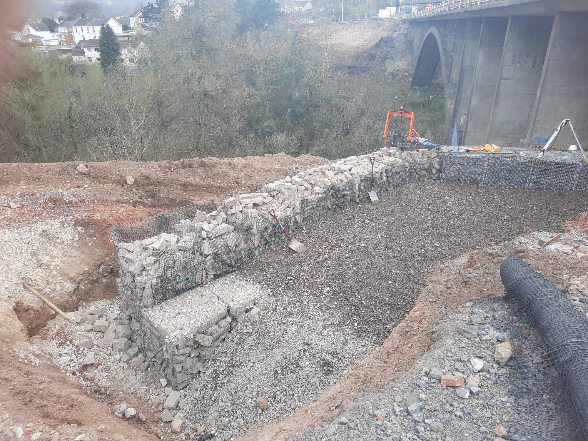
My project is a bridge strengthening and widening. In order to keep pace with the programme for the overall scheme, piling works must commence on my site on the 1 Jun 22. Pressure has been applied to start earlier. Currently on the East bank Gabion retaining walls for piling platforms (temp works) are being constructed and on the West Bank an access track cut so that retaining structures can be built there also. Both of these packages of work are forecast to be complete by late April (over a month in advance).
What has come to light since is several clashes with the permanent works which has forced a redesign of the temporary works. I have conducted my own initial review of the designers proposed solutions and believe that if they are accepted its likely that everything that has been built since my arrival on site may now be stripped out and rebuilt (which is equally soul destroying and comical). Not all of the materials used will be recoverable, meaning waste, environmental impact and cost. Plus the subcontractor executing the works has been charging day rates – further wasted cost. This is not only a significant financial expense, but also cuts into any profit share for both the public and private sector partners. In summary we have added significant cost and saved zero time – yet are still on track to be ready for piling on 1 June 22 so will not affect the overall programme.
To make matters worse, a 3D model exists of all the permanent structures on this scheme – by modelling the temporary works in the 3D models these clashes and issues would have been painfully obvious. Having asked why this isn’t happening I’ve been told ‘because the temp works change all the time its hard to model, we would have to keep re-modelling them’ – I was left pretty amazed by the reply, this is exactly why they need to be modelled! I am a complete convert to BIM for design and see just how beneficial it is to the industry. Having discussed this further with colleagues here I have realised just how unfamiliar any of the engineers are with REVIT or any other form of BIM.
I think for Design and Build to truly be beneficial and the benefits of BIM to be realised the process should be:
Partial Design (initial design) -> build virtually -> resolve issues -> build on site
What I am witnessing is this:
Partial design -> build on site -> identify issues -> re-design -> strip out and rebuild
Has anyone else had a similar experience? Has anyone actually saved time or cost in construction this way? What’s peoples experience on site been of BIM and modelling ahead of live construction?
What ARE we going to do with partial factors?
Firstly sorry about the Greek – difficult to do in this blog format
This si a live conservation regarding the current re-wrote of PAM 10 Structures for Operations.
The use of PAM 10 must be simple. It must be compliant with current structural design codes .
The current codes combine partial factor and limit state design.
The fundamental equation for ultimate ( failure ) limits states requires that:

the design effect is less that the design resistance.
Crudely we can determine
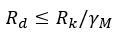
to get to the design resistance we reduce the characteristic ( usually mean vale to resistance, say , material strength) to ensure that it is statistically unlikely to be lower than the value used in design.
Although not straight-forward it could be envisaged that PAM 10 strength could be expressed as pre-factored so the resistance is determined directly using strength divided by a global gamma M ( for example C30 concrete has a strength of

The partial material factors used would be expressed in the refence documentation together with measures that PQE’s might take to vary risk.
The effects side of the equation is nominally
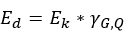
This implies we enhance actions to ensure that the design values are seldom less than actually applied . This is complicated by three issues:
| Issue | Description | Comment |
| Permanent .v. variable | Different actions are more variable than others. So permanent actions are increased by less than variable ones | Permanent actions are less variable than variable actions |
| Ultimate states .v. service states | Checks for failure Use the limit state in which the actions are factored up and resistance factored down Service checks do not factor actions( generally and use material properties that may or may not be factored | Generally stiffness is factored down for single elements but left at mean for systems ( like floor joists) |
| Multiple variable actions | When a design is checked with, say gravity and wind variable actions the dominant action is enhanced more than the secondary action | It is statistically unlikely that they are simultaneously at the extreme |
Since the narrative for PAM 10 is the management of risk – it seems sensible that some of the partial factor method is represented without having the full complication of full BS EN application.
We therefore would like the consideration of four possible options:
| Option | Resistance | Effect | Comment |
| 1 | Pre factored using recommended | Actions are pre-factored using appropriate gamma G and Q factors (ignoring further partial (psi) factoring of secondary variable actions ) | Resistance would be fairly faithful for design values Pre- factored actions would be difficult when either variable or permanent action dominated in a design . Would generally have to be taken on the high side |
| 2 | Pre factored using recommended | Actions are quoted as in various codes and are to be simply factored using fixed gamma G and Q partial factors ie ignoring further partial factoring ( psi for secondary variable actions ) | Resistance still recognizable Elements of the partial factor risk management seen in simplified action factoring |
| 3 | Resistance is to pre factored down using quoted gamma M and then further factored down using simplified gamma G,Q ( ie all the factoring on the material resistance side) | Actions are used, quoted as in various codes, without any factoring | Resistances would be about a third of the mean value Some conservatism would be embedded to allow for cases of high variable action component Actions used as is So ULS and SLS checks look similar in use |
| 4 | Resistance as quoted in BE EN with recommended partial factors quoted for use to be applied | Actions are quoted as in various codes and are to be simply factored using fixed gamma G and Q partial factors ie ignoring further partial factoring ( psi for secondary variable actions ) | Nearest to BS EN application |
DISCUSS
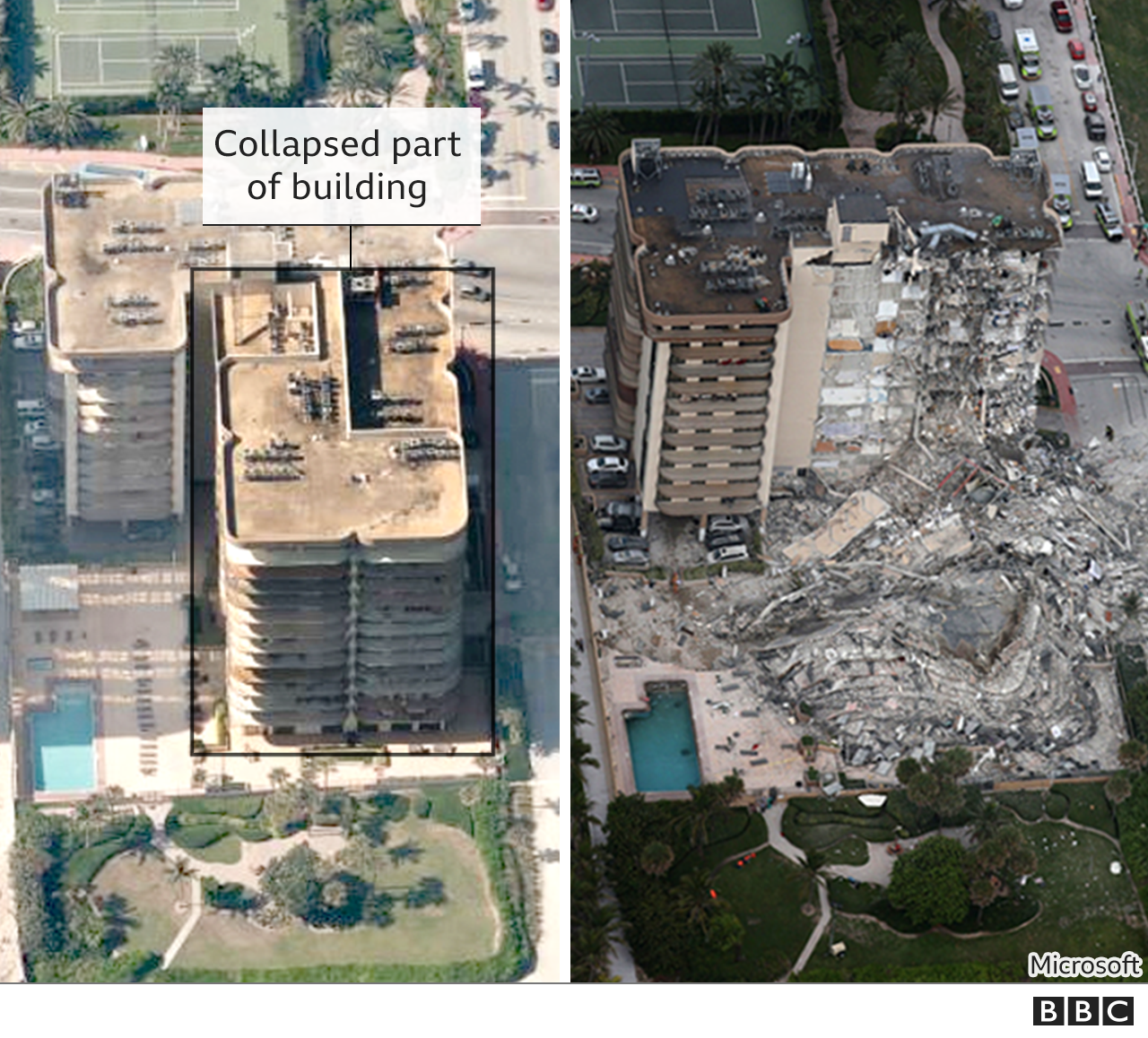
House of Cards
Do you remember the news of a Miami building collapse last year? 98 people were killed in the spontaneous collapse of an entire wing of the Champlain Towers on 24 June 2021. Official investigations into the cause will be ongoing for years but early reports are circulating of the assessed failures and how the second wing remained standing. If you haven’t already seen the Miami Herald interactive House of Cards article is it an engaging read (approx 20mins).
In summary, the assessed key failures include:
- Design failures & gross incompetence. The collapsed wing had smaller columns than the standing wing and critical suspended slab beams were removed from drawings prior to construction.
- Poor construction and refurbishment works. Only a fraction of designed reinforcement was placed in columns. Refurbishment around the pool did not remove existing works prior to refurbishment, instead adding additional layers of decorative concrete which which failed to reveal the over-stressed slab beneath and also added additional load to the slab.
- Structural damage / degradation. Slab cracking led to increased load transfer to the perimeter walls for equilibrium. This resulted in an over-stressed slab to wall connection which eventually failed and led to structural collapse.
- Neglect / lack of maintenance. The cracking slab led to water damage and flora ingress causing further damage. Leaks were common due to the structural deformation and these leaks were maintained but the cause was never investigated.
The building stood for 40 yrs balancing like a house of cards until the steel connections along the perimeter wall eventually fractured and the weaker wing collapsed. Obviously codes and building practices have moved on since 1980 and these failures are certainly avoidable but many high rise structures from this era still stand today, so how many of them are a house of cards? The official investigation report will provide lessons learnt and could have significant impact on maintenance of existing structures and future high rise construction.
P for Plenty
This post is probably about a two months out of date, but I wanted to blog about it because I’m genuinely interested to see if anyone else has seen a similar experience on attachment.
I have seen the ‘Go Big or Go Home’ philosophy applied numerous times in my professional career, both within and outside the military. Arguably, generous safety factors in military PAMs are just one contributing factor to the P for Plenty rule.
During my final few months of site attachment, I experienced the same phenomenon in the design of one particular intake louvre, at Mascot train station. This sparked my interest in the fundamental design of the louvre and the engineering principles that had been applied to reach the size specified in the design.
Safety
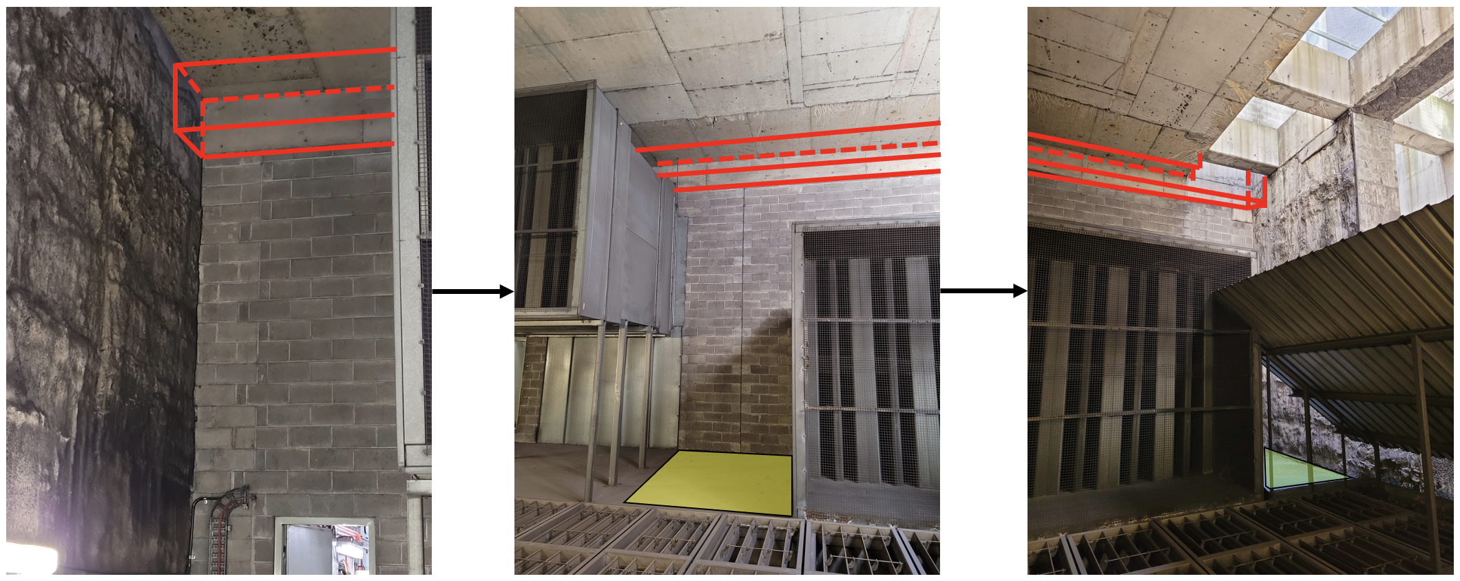
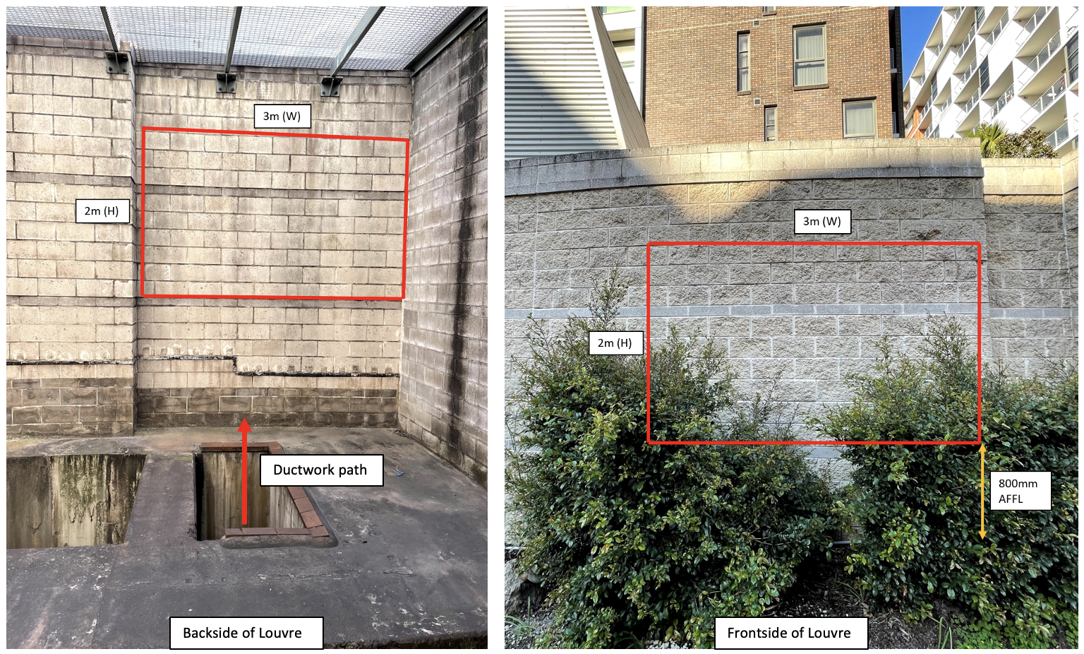
The main reason I took a strong interest in the design of louvre was related to constructability and safety concerns. The design positioned the louvre in a blockwork wall in the train tunnel exhaust structure of Mascot train station. Ductwork fixed to the back of the louvre would then convey fresh air through the exhaust room below and into the cable tunnel adjacent through the station diaphragm wall. Fig 1. below shows the exhaust room in more detail. I’m sure you can appreciate the access required (scaffold towers on the yellow and green areas) to install not only the ductwork at ceiling level, but also the louvre about 10m above the floor level.
Risks fall into two timeframes when constructing the louvre:
- The scaffolders constructing working platforms in the tunnel exhaust plenum for the mechanical and louvre subcontractor. The motorised floor dampers (automatically controlled) in Fig 1 lead straight down onto live rail tracks.
- The subcontractor constructing the louvre in the blockwork wall. The gaps between the concrete beams (shown in Fig 2) drop down >10m to the exhaust room shown in Fig 1.
Any reduction in the louvre area (original design shown in figure below) would not only reduce the risk exposure time for the workforce, but also assist the civil team in constructing the lintel above the louvre. My immediate question to those with civil/structural experience would be in the current markup below, the lintel would not have any blocks to rest on! Any solutions appreciated?
Design
I approached the designers and asked to see the calculations that produced a louvre area of 6m2 when the ductwork CSA is only 1.5m2. Basic fluid mechanics states that Q=AV and so I appreciate the louvre area (A) needs to be larger to reduce the face velocity (V) to achieve the same volumetric flow rate (Q) This lower face velocity at the louvre assists with water ingress, pressure drop, and public safety. However, a louvre 4x the size of the duct seems large!
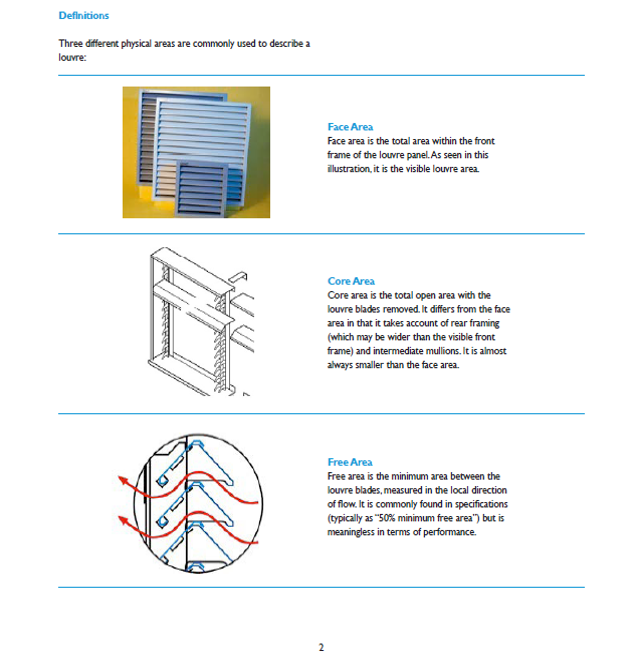
On further investigation, it appeared there was misuse of the louvre free area in calculation in addition to a generous safety factor and a design air face velocity of 1m/s. The free area is usually provided by the manufacturer and represents the minimum area between the louvre blades expressed as a % of the total louvre area. Numerous sources explain that the free area is meaningless in terms of performance and should only be used as guidance. More detail on the different louvre areas is described below.
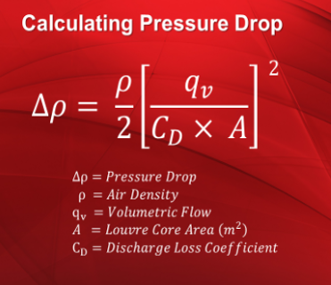
The two errors mentioned above led to a significant over sizing of the louvre. Running the numbers through a rearrangement of Equation 1 produced a louvre area of 4.5m2. After numerous discussions, the designers agreed to reduce the area of the louvre to 5m2, whilst still maintaining a suitable safety factor. This area reduction leads to a face velocity increase, however, the designers recommended two-stage louvre still maintained a 100% water ingress effectiveness at speeds up to 2.5m/s. In summary, the pressure drop and water ingress at the reduced louvre area was still suitable.
I’m intrigued to hear if anyone else has experienced over design, either through miscalculation or large safety factors on Phase 2 and 3? If so, what were the implications in terms of constructability, cost etc?
Common Data Environments / BIM Discussion Topic…
Does anyone on the blog have experiences of Common Data Environments (CDE) or BIM to share from their Phase 2 or 3 attachments?
What was good / bad about it?
What system(s) / software / hardware were used?
What user training was required?
If the system was in the cloud how was information security assured?
BS EN 16907 Europe’s first earthworks standard

The first ever European Earthworks Standard, BS EN 16907, were published at the end of 2018. This was the culmination of over ten years of detailed collaborative working by earthworks specialists from many European countries including the UK. The new standard treats earthworks design as a process.
The parts (contents) of the standard can be found below:
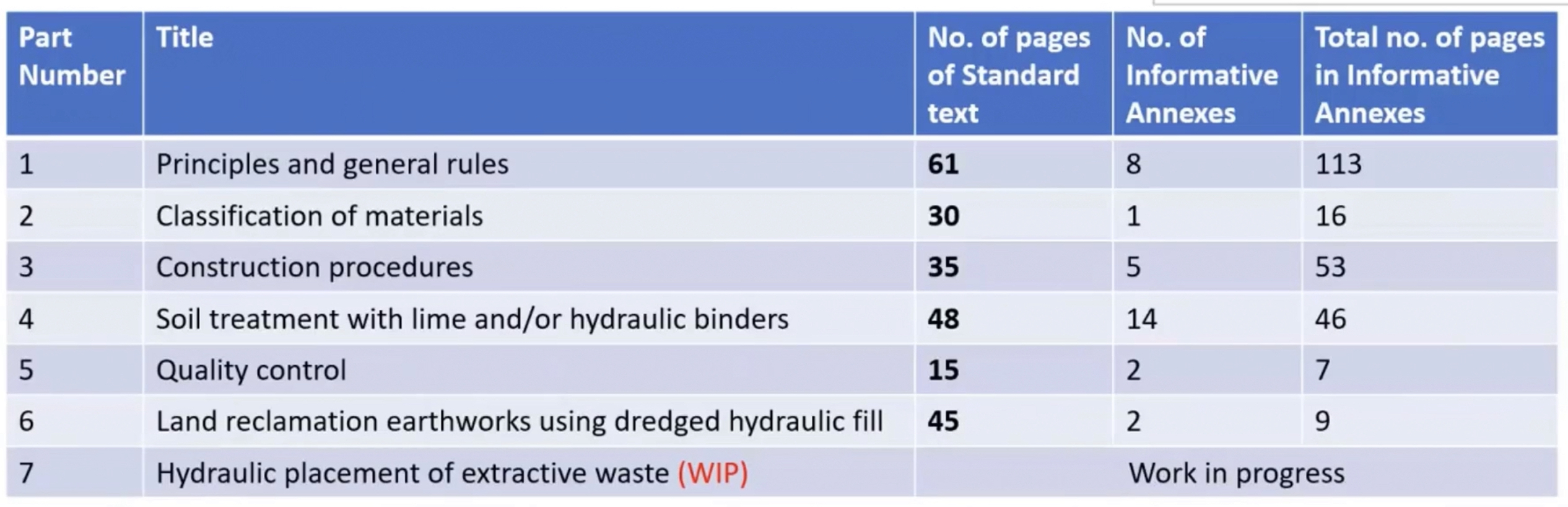
I’d be interested to know from anyone at the PEW if this is being taught to the MPFs? The MPFs on my team haven’t heard of it, they just recall Mr Moran shouting at them about the shear strength of soil.
If you’re particularly interested in this standard, the ICE released a lecture on it recently presented by some of the author’s of the standard – Link here.
Shaping Zero: The Big Questions
“ICE President Rachel Skinner asks the big challenging questions that will turn climate discussion into #ClimateAction.”
The civils students will have seen this in their emails today, but it might be of interest for E&M as well – follow up video from the (now outgoing) ICE President focussing on what we as (civil) engineers can do for shaping carbon neutral.
For those who haven’t seen the original video, it was released at the start of Rachel Skinner’s year as President:
#ShapingZero features a cast of famous faces arguing passionately for the urgent need to act on #ClimateChange. Experts interviewed included world-renowned explorer Sir Ranulph Fiennes, Chair of the UK Committee on Climate Change Lord Deben, former UK Secretary of State for Energy and Climate Change Amber Rudd, former ICE President Sir John Armitt, the Mayor of Los Angeles Eric Garcetti and the Mayor of Stockholm Anna König Jerimyr, Eden Project Founder Sir Tim Smit and several industry experts. All the experts featured agreed that climate change is the most urgent issue that #CivilEngineers need to tackle and that the wider public needs civil engineers to make that significant difference in the years ahead.
Zero Trim Piling
As infrastructure become bigger, heavier and more demanding of their foundations, piles are becoming more frequently used to support the projects. Piles can be either driven (eg. precast concrete or steel sections) or bored (eg. rotary bored, continuous flight auger, full displacement) into the ground depending on requirements for the finished pile and any restrictions or limitations on construction methodology. Bored piles are often filled with a polymer or bentonite fluid to support the open excavation before steel reinforcement bars (re-bar) is lowered in and concrete is poured into the excavation.
When a pile is cast, the concrete at the top layer is contaminated with polymer or bentonite fluid that’s used to retain granular material and support the excavation. The concrete is over poured above the cut off level (COL) and then after curing is removed leaving the re-bars exposed to act as starter bars for the structure or capping beam being constructed above. The adoption of a suitable pile breaking method can result in financial and programme savings and most importantly will address and reduce potential health and safety issues in relation to this phase of the works.
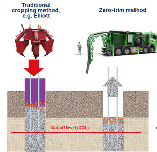
Traditionally this task of breaking out the concrete above the COL was done with a breaker or jackhammer, with operatives carefully trying to break out just the contaminated concrete and not damage the re-bar or good concrete below the COL. Other established methods use a pile cropper mounted on a 3600 excavator or high pressure water to remove the concrete above the COL.
The traditional method has health and safety risks associated with HAVS, confined space work, silicosis and working at height. Using a pile cropper eliminates some of these risks but still creates dust and risks damage to the concrete below the COL or the steel starter bars and using high pressure water requires specialist equipment and contractors onsite.
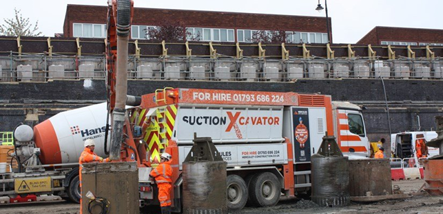
The “zero trim” pile technique that has been trialled and will be used by SCS JV for contiguous piles in Area East and D-walls in Area Central involves the use of a vacuum excavator (vac-ex) to immediately suck up the over poured, contaminated concrete down to cut off level before curing. The pile is then backfilled with shingle and the vacuumed concrete recycled. This has benefits in time, cost and quality as well as health and safety – over the 750 contiguous piles in Area East it is expected to save 60,000 working hours breaking piles and save over £374k of costs associated with pile cropping.

Methodology
The pile is drilled as normal under the support of bentonite or polymer support fluid. Reinforcement cages are lowered into place as required. Tremie pipes are lowered into the pile and concrete poured through them to fill the pile from the bottom up with the support fluid being taken away for treatment and reuse. The concrete is poured above the cut off level (COL) as the top layer of concrete will be contaminated with the fluid. The vac-ex is used to take the excess concrete and fluid mix away and reduce the level to the cut off level, exposing the re-bar to be used as starter bars. If required (generally for tension piles where the COL is a long way below ground level) the casing is then filled with shingle and removed.

Benefits of Zero Trim Piling
- This technique removes the need for any work that will cause HAVS, silicosis or confined space work. There is no noise from breaking the concrete out however the vac-ex is noisy and PPE as well as collective noise barriers can be used to mitigate this risk.
- The vac-ex is compact and can fit onto any site where a concrete wagon will discharge and its small boom allows it to operate close to site boundaries (including ones with restrictions such as Network Rail (NR) boundaries without additional restrictions in place.
- There are significant carbon savings in the technique as the over pour is less than with traditional methods. For the 1,140 piles in Area East of the SCS JV work on HS2 it is estimated there will be a saving of 820,000 kg of carbon dioxide emissions.
- There are further positive benefits, including noise reduction which is important for projects like HS2 where construction is taking place within communities and near operational businesses. There are also considerable cost savings and environmental benefits as the new technique uses less concrete, reducing carbon. On the SCS sites the extracted concrete is being retained on site and being reused in construction elsewhere. This reduces carbon in construction, including through reduced lorry movements to and from site.
Trials of the method have been completed and the concept proved. Further data proving the quality and refining the method are ongoing on both temporary and permanent works for SCS on HS2.
I’ve anecdotally been old this method has been trialled in other parts of the world but have not been able to find any literature to evidence it. As far as we are aware at SCS this method hasn’t been used in the UK ever. If anyone can shed any light or knows otherwise please let me know.
Further information can be found in various media articles in the comments and if anyone is interested in more details I can send you a TMR on the topic.
The Elephant in the Room – Population Control
In preparation for my professional review I’ve been doing some research into the Bruntland Report ‘Our Common Future’ and was looking to see how much it influenced the United Nations Sustainable Development Goals.
For the most part it seems that many of the points raised by Bruntland do feature in one way or another in the SDGs… with the exception of population growth – the elephant in the room.

Below are some excerpts of the report regarding population growth:
The planet is passing through a period of dramatic growth and fundamental change. Our human world of 5 billion must make room in a finite environment for another human world. The population could stabilize at between 8 and 14 billion sometime next century, according to UN projections. More than 90 per cent of the increase will occur in the poorest countries, and 90 per cent of that growth in already bursting cities.
In many parts of the world, the population is growing at rates that cannot be sustained by available environmental resources, at rates that are outstripping any reasonable expectations of improvements in housing, health care, food security, or energy supplies.
Urgent steps are needed to limit extreme rates of population growth. Choices made now will influence the level at which the population stabilizes next century within a range of 6 billion people.
Given population growth rates, a five- to tenfold increase in manufacturing output will be needed just to raise developing world consumption of manufactured goods to industrialized world levels by the time population growth rates level off next century.
The rapid rise in population has compromised the ability to raise living standards.
Our Common Future, Bruntland
Given how heavily the idea that population growth should me managed/limited featured in the Bruntland report, I found it interesting that population control wasn’t explicitly mentioned in the UN SDGs.
There are both political and ethical issues when addressing population control, not least because population booms are typically occurring in less developed countries.
But the point remains that population growth is one of largest threats to the climate in the short term, yet it’s too delicate of an issue to address. What’s the solution?
Elements of the issue are explored in more detail in a blog post here.
