Archive
They said I was mad to build a castle in a swamp!
Monty python-Holy Grail
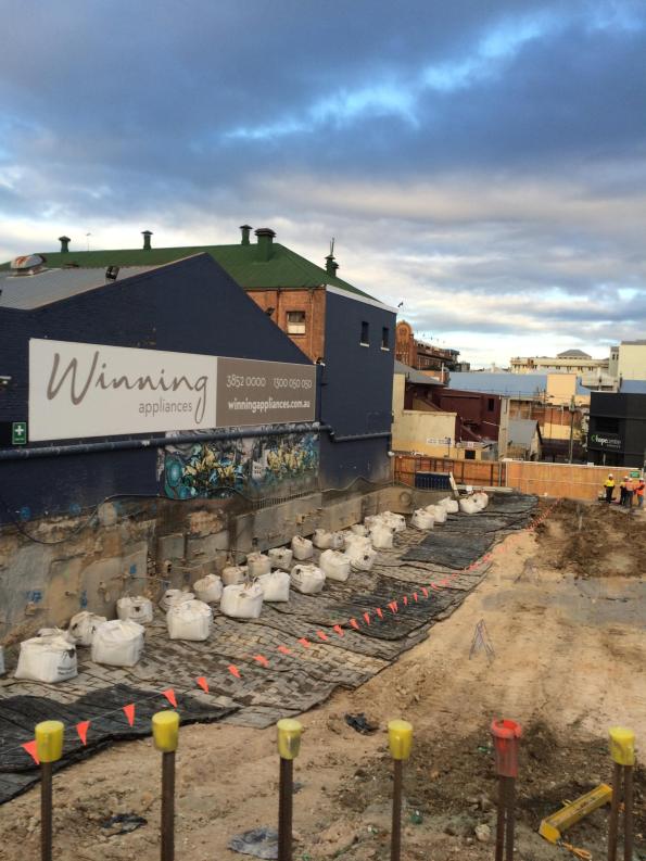
In my last blog I mentioned building a basement in a swamp. The tender is on a brown field along a tributary of the Brisbane river known as Breakfast Creek. The site that has recently been cleared (ish). On my recce I began to feel a sinking sensation in the pit of my stomach. The ground here is truly awful but, the client is adamant that he wants his basement.


Design. The structure is a 6 storey Mercedes show room/car museum with a single storey basement. The client’s design calls for a temporary retaining wall and then a concrete bath tub to keep it watertight constructed on the inside temp retaining wall. The structure itself will be supported by pile footings. It was originally tendered as a Traditional construct only package but, due to the risks is now being let as a Design and Build.

Boundary. Argillite bedrock between -7 and -31 m. Level of Bedrock varies across the site from -7 m in West to -31 m in the East.
Properties. Very Soft Alluvial Clay φ’ = 25 ° and c’ = 0 until Hard Argillite Rock.
Groundwater. Tidal range of RL +0 to 2 m (+3.5 m flood level)
Contamination. You guessed it ASS is back. With some potential hydrocarbon contamination.
Issues. The client wants this basement even if it costs him $5 Million.
- It is a swamp! It is possible to cantilever 5 m in this rubbish but the toe stability is the problem. The solution at the moment for sheet and contiguos piles is to have every 3rd pile down to the base rock which can be up to 31 m.
- The pile loads for earthquake loading are massive. Brisbane isn’t in a seismic zone but like all building it needs to be design to withstand a basic seismic. The problem is that because the neighbouring soil isn’t worth a damn the tension loads carried by the pile foundations are over and above what you would expect of a 6 storey building.
- Hydrostatic slab. Given the high ground water level, the basement needs to be designed for a hydrostatic slab. The original design calls for beams to carry this load but, this will be a nighmare for something that cannot achieve a batter of 1:2.
- Heritage structure. An existing heritage bridge abutment (not in use) is on the perimeter of the site and it cannot be damaged, despite the fact that it has failed.
- Existing retaining walls. The client also wants to keep any existing retaining wall structures that have been left in place. Unfortunately, the existing retaining walls from the previous structure show signs of distress. It appears that their is disproportionate settlement in at least one part of the retaining wall. To make matters worse there are no as-builts of the retaining wall structures.
Upside – The hotel where I took this photo does massive steaks and great red wine – so that’s how I spent the afternoon. If all recces were this good
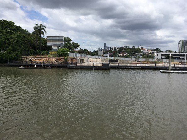
View South from opposite bank (bar). Failed heritage abutment on left. (Note high tide)
Calcs v Real World
Hambly’s Paradox…

A man weighing 600N sits on a three-legged stool. The stool is symmetrical, the man sits in the centre of the seat. What basic force should each leg be designed for?
The same man now sits on a square stool with four legs, one at each corner, the stool and the loading are symmetrical. What force should each leg of the stool be designed for?
Rock blasting in the middle of the city!
Blasting next to a heritage bulding in Fortitude Valley, Brisbane City
So I am currently assessing how to build a 4 m basement car park in a swamp with a CBR of 1.5. I could go into the details of that but, while researching my thesis I came across these videos of blasting in two of my case studies Fortitude Valley and 300 George Street which are far more interesting. How do you get away with blasting very hard rock in the middle of a city? With a lot of careful planning. Note the mattresses to prevent fly rock and the drilling before hand in the 300G video not just for placing the explosives but to localise the effect of the shockwave

Details of the blast
Building Energy Efficiency
How do MEP engineers design a building for energy efficiency? This was a question that had often kept me awake at night…. fortunately thanks to the first few weeks at a design office I have an idea of how the process works. This blog will briefly run through the process of designing the building MEP to specify equipment and meet the UK energy efficiency (Part L) building regs.
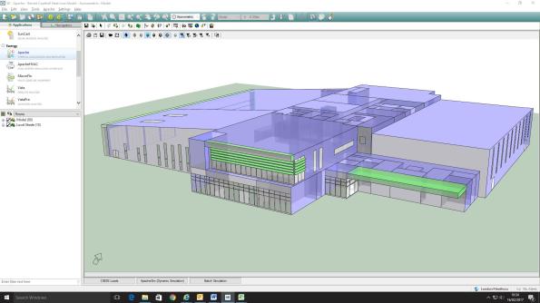
Building thermal model in IES – Hevacomp for grown ups
First of all some principles of how the design office operates (so far):
- Minimise time. Time is money for the design office; they are very fastidious about budgeting time to a project in advance and accounting for the time spent. Therefore only the minimum design work is undertaken. g. pump size on the longest pressure drop, don’t both with checking anything else.
- Deliverables drive the project. In conjunction with the previous point; Bryden Wood will only produce a model when they are required to do so, otherwise Excel is generally used to do the job. In my first project the client has paid for a Revit model update every two weeks, but all equipment sizing is done on Excel. The data in this model is minimised to limit time wasted; for example pipes are shown uninsulated as it would take time to draw it on, drawings are not colour-coded, etc.
- Energy Efficiency Legislation is met (just). There is no advantage to the client of smashing the energy efficiency legislation… this would just waste money. The equipment and building materials have been spec’d to meet the legislative requirements and no more.
- Minimise Responsibility. The MEP team is only able to influence a small element of the overall building performance; designing MEP equipment. Unfortunately we are required to predict the entire building performance – which is influenced by the number of windows (architects), orientation (arch), structure (civils), etc. Therefore time is spent recording other stakeholder’s decisions to protect BW if/when the building fails the performance checks.
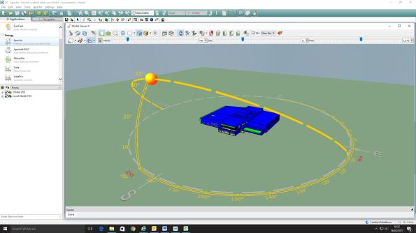
Sun path graphic for Barnet leisure center. The program will include solar gains for rooms.
My first project has been the MEP fit-out of two leisure centres in North London. In very simple terms the design process has been:
- Develop Strategy. A scheme for the MEP design is developed based on building use and client wishes. This is generally based on experience within the design office and the clients’ spec; for example the swimming pool will be served by an Air Handling Unit (AHU), Café will have underfloor heating, etc.
- Rough Equipment Sizing. This is undertaken on a big Excel spreadsheet with details of temperatures, room internal heat loads, fabric losses etc. All very reminiscent of the PEW design exercises, based on CIBSE or ASHRAE references. Loads are summed (with a bit of fudge factor diversity) to give approximate plant loads for the building.
- Select Manufacturers. The client has a list of preferred manufacturers who get involved with selecting the equipment for role based on the rough loads calculated above. This stage has an element of project management to it, and a few free lunches.
- Develop Thermal Model. Dedicated Integrated Environmental Solutions (IES) software is used to model the thermal characteristics of the building, in parallel to stage 3. This adds more accurate numbers to allow detailed plant sizing and includes solar gains, heating profiles, etc. The full potential of this software is not used to save time – for example, instead of modelling the transient (or warm-up load) for the building the equipment is sized on the steady-state load +15%!
- Confirm building meets Part L. The IES program is one of four approved to determine whether a building will meet the legal efficiency requirements. Detailed system information is added once plant has been selected, then the program produces an Energy Performance Certificate (EPC) and Part-L compliance certificate.
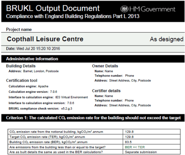
The finished Part-L compliance report
In all this process will have taken a team of three about 12 weeks to complete… a bit more relaxed than the single week we are given on the building services design exercise at PEW.
Permissible Stress or Limit State Design?
Hopefully this blog won’t be as boring as the title suggests?….
Even though it was a very long time ago….. I remember being at university and learning about permissible stress design (it obviously wasn’t a Thursday morning). At the end of the lecture a wise old professor informed us all that we’d never actually design anything this way, that it was pretty much obsolete because everything was moving well and truly towards the future…. and the limit state approach. Indeed, when I worked in industry prior to joining the military I found this prediction to be true, and the idea was reinforced during Phase 1!
Imagine my surprise when I arrived in the US and found that, rather than being a bastion of enterprise and advancement, the US actually embraces and encourages the two design philosophies to be used in parallel! Over here they are known as ‘Allowable Stress Design’ (permissible stress), and ‘Load Resistance Factor Design’ (limit state). When I say ‘encourages’, this isn’t quite fair. What I mean is that the American Institute for Steel Construction (AISC) publishes both methods side by side in its design manuals, allowing designers to pick which method they prefer. Interestingly, concrete did make the jump years ago, and no longer practices ASD.
So I’m currently designing a glorified giant dog kennel and training facility for some fierce secret service working dogs. I’m working to ASD for the steel and masonry, which is nice because it makes things simpler and I don’t have to worry about any complicated plastic analysis or behavior etc…. it’s also handy because all of the joists come from the manufacturer designed and specified using ASD. Nice and simple. Until it comes to designing the footings, which of course being concrete mean that I had to alter my loads using a crude conversion factor of 1.4 to ‘upgrade’ them from ASD service loads to LRFD design loads! But even then the fun isn’t over; the soil bearing capacity (4000psf John, very stiff!) isn’t factored, so I need to multiply this by an additional ‘resistance factor’ so I can work in LRFD, making sure I don’t accidentally divide by the ASD global ‘safety factor’ instead, because that would be a disaster! Who needs a sinking building and (expensive) squashed mutts!?

My Design: Permissible Stress or Limit State? Why choose, have both!
Apparently things are improving! Until recently live load and dead load factor of safeties for steel and concrete construction using LRFD where different! 1.6 & 1.2 for steel and 1.7 & 1.4 for concrete; imagine having to swap between the two sets whilst working with the same philosophy on the same design! You all thought Euro-codes were frustrating, you’ve got it easy! Also, (and back to the point) the AISC are apparently considering removing ASD from their manuals which will be a step in the right direction! However I’m not holding my breath; it takes a long time to buy a stamp over here, imagine how long it might take to alter something as ingrained and controversial as this.
This all seems like madness and an accident waiting to happen… and it nearly it! During my time on the JOC project over at East Campus it was discovered that a series of giant steel trusses had been sub-contracted out to a ‘specialist’ by the designer. When they were finally delivered to site it was discovered that they, together with all the connections had been designed using ASD rather than LRFD loads. On checking the truss turned out to be fine (phew, almost a very expensive error for someone), but all the connections were under-designed by approximately 40%! These trusses were very nearly installed, and it was only scrutiny of the drawings at the beginning of the week of installation that prevented fundamentally unsafe construction! Whilst it is considered bad practice to mix design philosophies, in my experience it seems to happen an awful lot. Particularly on simpler, small projects that need to be turned out quickly, and by older-generation engineers who grew up with ASD and see no reason to change.
I was wondering if anyone else had had any experience of permissible stress design during their attachments? Surely if there’s a slow backwards nation that can stand with America on this one it’s Australia?! Or is it really only America that lacks the will to embrace change?
Grease build up in Non Return Valves
BLUF: Can any of you geeks point me towards any discussions or case studies on the effect that fat, oil and grease (FOG) has on (NRVs?). I’m guessing it’s not going to be good but I need to know how bad it could be, maintenance periods, dosing options.
Background:
I’m working on the adaptation of the drainage for an existing department store in London. Over the years the store has developed a maze of drainage, both foul and rainwater, no-one really knows how it works and there is a history of FOG build ups causing blockages, and being London concern regarding rat ingress.
There are around 20 proposals to fix all the issues. Two of these are flap type NRVs to prevent rat ingress, and grease traps with a wider grease management process. However, there are areas where in the short term (2-10years) we will not be putting in grease traps for commercial reasons and so there is concern over whether fitting the NRVs to this section would make grease problems worse. The store doesn’t have a great record of maintaining the system so “just check regularly to prevent blockage” probably won’t be successful.
Optimistically I’m hoping that the pressure required to operate the valve may be enough to clear any FOG build up but I guess this would depend on what volume and the frequency of flow, and what type of valve we specify.
Innovation. The conclusion of the trilogy.
The long awaited concluding part to the innovation trilogy. Spoiler alert – RF was right. It’s about risk appetite and opportunity. Feel free to stop reading now if you can shout that at the reviewers with enough confidence to convince them you know what you’re talking about. If you want a bit more information up your sleeve then see below. Alternatively wait until Disney buy the rights to make the Innovation Trilogy and then watch the film.
Most of this is based on discussions with the authors of “Innovation in Structural Engineering – the art of the possible” published in The Structural Engineer Jan 2017. I won’t cover the report in detail as i’m sure you’re all keen to read it. I also sit on the Expedition Sustainability Group (SG) with two of the authors, and we’ve discussed some of the wider issues in our meetings.
To quote the US Administration and Tom Clancy….”there is a clear and present danger [from innovation*]”. (*also drug cartels but that’s for another day). Therefore Clients are wary of it and there must be a demonstrable benefit (potentially T, Q or C). The sustainability group believe that to implement innovative solutions they need to contribute to both innovation (pushing the boundaries) and sustainability. I think they missed out the key requirement and that it also needs to be functional. If the proposal falls within all 3 of the circles below and has monetary saving it will be difficult to argue against.
![20170211_132843[830].jpg](https://pewpetblog.com/wp-content/uploads/2017/02/20170211_1328438301.jpg?w=595)
One of the authors (Jones) presented his research to the SG. He thinks whether innovation can be realised or not can be expressed as below:
Initiator + Enablers = adoption
Requirement, constraints, Resources, skills
aspirations
The article cites earlier research suggesting that likelihoood of adoption primarily depends on five factors:
- Compatibility – how well does the innovation work with what already exists.
- Complexity – how easy is it to understand the innovation.
- Observability – can the success of the innovation be visually demonstrated. (In the case of SNFCC literally jumping up and down on one of the prototypes was one of the most effective demonstrations – despite being completely unscientific)
- Trialability – Can you safely test it or is it just a punt
- Relative advantage – How much T,Q,C is improved
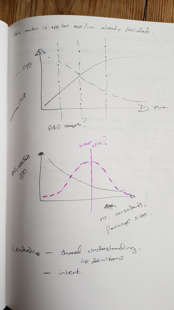
In addition, as I mentioned before, there are unintended contractual barriers. Many innovations may not be realised due to the Client/QS and the way they have tendered the works. We will all be familiar with the opportunity for change versus cost of change graph (top graph below). I think this can be applied to innovation and that right of where the two lines cross, you’re unlikely to see an innovation unless the saving is enormous. Depending on the nature of the contract, the amount of D&B, the size of the packages and when they are tendered, the position of this crossing point, in conjunction with the RIBA stages, will change. The lower graph shows my thoughts on the number of consultants/number of packages. Initially I thought that the more consultants or specialists you have, the smaller their packages of work will be, and the less opportunity there is for innovation. On reading the innovation article, I then revised this to suggest that there might be a sweet spot with enough specialists for a broad range of experience and knowledge, but still maintaining a large enough brief to be able to make savings within each tendered package of work. Put bluntly, why would one designer make a change that would benefit another consultant or contractor’s work package.
Of the 5 factors listed earlier, trialability is the most interesting to me because I had no idea how this would be approached in a military engineering context. It was also one of the biggest challenges on the Stavros Niarchos Foundation Cultural Centre (SNFCC) project., when they wanted to use ferrocement to provide a thin canopy on top of the building.
The team highlighted 3 methods of trialling. The cheapest is to look at other industries or projects that have implemented something similar, proving the material in a different context (or perhaps even the context with a different material? but this is trickier and less likely). This leaves a gap which needs to be bridged with supporting calculations, and is therefore relatively risky. (I think Concrete Canvas have found it difficult to progress from this option to the next option)
The next option is to combine physical models, computer analysis, and prove the innovation from first principles. The level of proof and risk with this option varies massively. Generally the more physical and less conceptual the analysis, the more you can tick off complexity and observability. Providing, that your modelling assumptions are correct.
The final option is to gain certification of compliance through formal testing against specific performance requirements. This is expensive and often outside the scope of an individual project, but can deliver a good level of confidence and consequently a low risk of failure.
The successful SNFCC project used all 3 of these approaches. With the above in mind does anyone know if we used any of these techniques on operations or on PDT?
The SNFCC canopy innovation was ultimately successful because it had the right project team, but this was not an accident. The Client was actively seeking out innovations and had a budget to support this. Expedition understood the intent and set about to secure a team of academic and industry experts to support them in their quest. The project was tendered competitively with the project team demonstrating a viable construction solution to potential contractors. This meant that there were less unknowns, and therefore risk for the contractors to have to price.
The so what for me is that I don’t think i’ll come across many clients actively seeking innovation in the next few years. However, I might be forced to implement innovations to overcome other barriers. If this is the case then i’ll need to decide upon and implement a testing/proving process to demonstrate management of the risk, and a real benefit. I’ll also need to have access to the right team to support me, which means understanding the reachback to 170, academic staff, the wider Corps and the invaluable Engineer Staff Corps.
Expedition is considering forming a technical working group to investigate the potential for reducing the partial safety factor for reinforcement, and safety and material factors in general, following a recent academic paper by Beeby and Jackson. I’m hoping this will allow me to develop a methodology for evaluating some of the safety factors used in military engineering.
Efficient Detailing of PT
My boss has buggered off to Melbourne for a couple of days and so I am having to seveerly raise my game.
I am looking at detailing a slab and found this usefule- please see attached link on guidance on efficient PT design. PT Detailing
TC Design – Practical Application of SA Techniques
It’s been some time since my last blog as I was away for a bit on holiday, it was great to see everyone out in Oz. I have now been back to work for a few weeks and am safely embedded in the Robert Bird Group (RBG) Construction Engineered Solutions (Temp Works) Team. I asked to go into this department in the hope it would allow me to get plenty of short, sharp tasks that would expose me to a broad range of experience whilst developing my SA skills.
Currently I am designing an embedment plate for two Tower Crane Ties. The example below shows one of the double brackets specified by Terex that I need to connect to the embedment plate I come up with.
I was given un-factored reactions, also by Terex, all of which are acting at point A as annotated on the second Dwg.
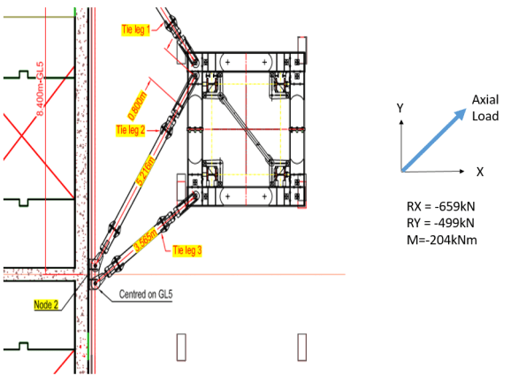
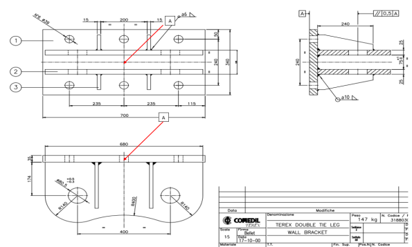
Put simply, I am trying to transfer the loads given into my reinforced concrete core wall. I started by factoring the reactions and conducting analysis on the back of the bracket to determine the maximum tensile loads likely to be seen in each bolt position (36mm dia bolts). Ideally my anchorage re-bars will tie into this plate with couplers that connect to 36mm dia bolts protruding through the holes you see on the dwg, also giving me the tensile load in my anchor rods.
For those who are bored or, particularly for those currently on phase 1 who enjoyed the SA exam twice like I did, it’s a good problem to get a feel for how the technical analysis skills you are taught on phase 1 are used daily in a structural engineer design office. Even after 11 months on site watching Irish blokes pour concrete it didn’t take long for me to get back into the swing of this stuff and weirdly, I’m now actually starting to enjoy it.For obvious reasons I was mildly apprehensive about this phase of placement but as it turns out I find it much easier now I can apply it to real world work.
I’ll try put up some of my workings in a few days but as a starting point you clearly need to design a solution that deals with all the forces acting on the bracket in this condition. The means by which you model this bracket significantly changes your loads. (Note: I also resolved this with the axial force in the opposite direction shown but as it gave a very favourable pre-stress the tension issue is negligible in that condition).
(Once you’ve done it using all three rows of connection points, try deal with the moment using only the central two bolt positions as this is a design constraint I am working through at the moment due to the geometry of the core wall).
Australian Structures Codes Cheat Guide
For those that are struggling with the Oz codes for detailing reinforcement or are shortly to deploy – I was struggling with lateral reinforcement for a prestressed bar to tie in a crane. I found this excellent presentation. It has certainly helped jog my memory.
