Archive
Concrete Chaos
A few weeks ago we completed the first of our substantial concrete pour operations in order to construct the main tower core pile cap in our basement. This is a big block of concrete. The pile cap is roughly 18m wide, 36m long and 3.5m metres deep giving a total C32/C40 concrete volume, with quite a few lift pits thrown in for good measure, of 2830.5m³. We are constructing it in four roughly equal sections. During the first of these pours we emplaced 610m³ of concrete in one go. The pile cap will eventually carry roughly half of the 40 storey towers structural load so getting this right in terms of quality is important. This task was also on the critical path so ensuring it went in error free and on programme was a major concern. As the blog title implies, all did not go to plan.
Whilst my ability to walk over re-bar mats without looking like an amateur construction worker is improving rapidly, even I felt reasonably uncomfortable being stood on top of the cage suspended 3m in the air with clear sight to ground. The top mat re-bar inspection is probably the most unsafe I have felt at any point on this project. The potential to fall through a hole in the mat or beak an ankle/leg was alarming, as such work was stopped on multiple occasions to address H&S concerns. Thereafter I took to doing re-bar checks from Ground level looking up. Despite its considerable size the re-bar cage is a surprisingly simple design made up, in general, of 32mm dia bars at 200mm spacing’s. We have 4 layers in the top and 4 layers in the bottom.

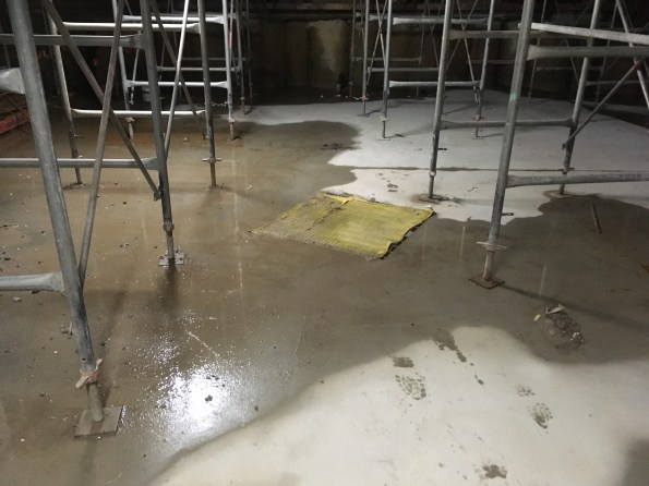
Unlike most concrete pours the interesting thing about our methodology is that once the formwork is stripped away it’s conveniently easy to inspect a complete face of the pile cap throughout its whole depth. This makes post pour quality assurance checks considerably easier for the main contractor whilst also making it more difficult for the sub – contractor to hide any poor work underground.

The above picture shows the top 1.5m metre of our 3m deep concrete pile cap once the formwork had been removed. The structural engineers were initially quite concerned about the concrete quality. If you look closely you can see horizontal lines running in the concrete throughout its complete depth. Initial concerns were that the pour process had enabled horizontal cold joints to form between delivery loads of concrete. Had that been the case, then we were concerned we had produced a concrete block with weakened shear planes running through it. The question I tried to get answered was: why is this a problem? As I see it; If you simplify the pile cap in the permanent condition and consider it a large beam (the concrete block) carrying a large UDL (the tower) through numerous evenly distributed supports (the load bearing piles) then I think you would end up with a very simple FBD and BM/ SF diagram. With a few convenient assumptions and a quick check on google I think it would like something like the following
If indeed this pile cap behaves like a beam (And not a reinforced deep truss) then it sees greatest shear over the pile positions. Under the load of the completed building multiple horizontal cold joints caused by poor installation will undermine the capacity of the concrete pile cap, particularly in those positions. As it’s such a vital structural component stripping out this concrete and starting again was suggested by one overzealous member of the construction team. That was quickly put on hold because breaking out 610m³ of heavily reinforced concrete would be very unpleasant, not to mention crippling for our tight programme. As such an investigation was completed and after chipping away 30mm of concrete face the effect disappeared and with it the concern over the complete block. Had it continued we would have cored into the concrete block in a desperate search for any shred of evidence that would have prevented the need to strip it out.
Interestingly, even had we found weakened horizontal shear planes running through this mass of concrete, automatically stripping it out would have been a hasty reaction. When you look at it simply, all we need to do is install a solution that allows shear to be effectively transferred between the layers. Conceptually this could also be achieved by post fixing shear links into the pile cap by drilling and installing vertical reinforcement steel rods through the concrete. If we emplaced enough steel, focusing on the areas where the shear is known to be greatest, it is likely we could provide enough shear resistance to mitigate the long term risk. This would be difficult but considerably easier, quicker and cheaper than stripping it all out and starting again.
We are still unsure what caused this effect so consistently. In general concrete work seems reasonably poor quality across site. At the time I asked the concrete sub-contractor what lessons they had learnt and what measures they were putting into place to improve this process, they couldn’t give a particularly good answer; concerning when you consider our next pour was 850m³ of the stuff.
Attention blog administrators.
The blog memory if currently at 99.9% of its 3GB capacity, if we reach 100% there can be no more blogs………..
My slightly unorthodox Ph2/3
It’s nearly November and I guess most people are starting to get towards the end of their site phase and are looking forward to a bit of leave and then the design phase (hopefully one or two people are thinking about growing a moustache). Early on in my attachment I decided to try something a bit different and sought to combine both Phase 2 and Phase 3 into one Phase 2.5. There were a couple of key drivers for this:
- The project is due to complete in June 2017, so I would be able to see the services element of the project from design development, to installation and through to commissioning and handover.
- When I joined the project there was still a significant element of design development going on: everything from high level services coordination and clash prevention, to user workshops to refine whole room layouts and to finalise designs for key elements within the clinical spaces. This meant that there was initially very little on-site activity for services but it also gave me exposure to some of the design competencies very early on.
- The services manager on the project wholeheartedly embraced the concept of the attachment and was able to organise attachments with subcontractors and consultants in order for me to gain exposure to detailed design concepts, requirements and software.
- The possibility of an extended secondment to Multiplex’s head office to work within the New Projects Department for exposure to the commercial and contractual elements of tendering and resourcing multi-million dollar projects. This has recently been confirmed and will be timed to coincide with the production of my draft thesis.
So far everything has been running fairly to plan – below is a snapshot of these I think I will be come the end of my Ph2.5.

I have highlighted the B competencies in the chart as I believe that of the 5 areas, the design will be my weakest come Ph4 and I will be relying heavily on the experiences gained during my 18 months working in an Oil and Gas design office before joining the army, the design development work from the St George Hospital Project and the short secondments to subcontractors and consultants.
Despite possibly leaving me slightly exposed in the B competencies, I believe that the experience of seeing a project from start to finish will greatly out-weigh the lack of detailed design experience. And I guess if I am wrong then I will just have to come back to Oz and give it another go!
Poo Pipes
I learnt a few things about drainage last week.
Firstly – When Richard Farmer said that you need to plan your drainage and external levels before you build the structure, he was actually right.
Secondly – No-one in the office knows anything about designing drainage layouts other than reciting age old rules of thumb.
Thirdly – Never admit to having done a module on something unless you’re prepared for it to come your way.
Finally – Never trust Thames Water.
The problem
The new office at Chambers Wharf consists of a three storey stack of 96 cabins. The internal layout for this was practically written up on a fag packet for approvals purposes and not really looked at since. No designs were ever completed for the outside of the offices so the drainage runs, street furniture, steps and ramps, and access control now need to be shoehorned into a small gap between the office and the hoarding. Rather than working from 1 level, these features must tie in between external footpath level, internal FFL, and new office threshold level. The office must open on 31 October or 200 people will have nowhere to work.
We have also just learnt that the manhole that the site has been pumping it’s waste into for the last 2 years, and for which we have a discharge consent from Thames Water, is not, and never has been connected to the main sewer, but has been flowing back into site through an abandoned connection.
With less than a month to opening the office, everyone has just decided that they have a crucial requirement for the outside of the office (including bike racks, money gates, artist studio, and parking), and that now is a reasonable time to request it, although they don’t quite have all the details yet.
The solution
It seems impossible to keep everyone happy but turning to my trusty copy of Civil Engineering Procedure and the Joint Board of Moderators guidance (2009), it seems that I have a chance to use this to “demonstrate an ability to cope with the uncertainties of a multitude of factors making up the design brief.”
I’ve prioritised the things that we need to provide for office opening. Namely access and drainage. All of the other stuff is important but we can still occupy the office without it.
The drainage pipe had already been specified (by rule of thumb) as 150mm. Being a competent engineer I knew that using a rule of thumb was risky so I spent a morning looking into the Building Regs and speaking to the cabin manufacturers, and calculated the required pipe diameter. Turns out we need a 150mm pipe. Unfortunately there is no plan for greywater recycling. This would have greatly reduced the load on the system.
I then designed the external drainage runs (see attached pdf) and access points in accordance with the guidance in Part H, and the surrounding floor levels will be set to suit. Some compromises have had to be made. Most notable that in some areas the pipe will be laid with less than the recommended backfill, and in others it will be on the surface and boxed in. But that’s what you get for not thinking about it beforehand.
After a number of investigations, Thames Water have finally accepted that it’s their fault we’ve been draining our poo into an abandoned manhole and have agreed to make a connection, but the timescale is uncertain. In the meantime we will be installing a new manhole inside the site and if they can’t meet our timescales then we can install a macerator pump within the manhole to pump our sewage around the site to an alternative discharge point.
Now I just need to hope the showers don’t fill with poo before I go to Phase 3.
I smell gas is that your ASS again?
Just when I thought that I had heard the last of Acid Sulphate Soils (ASS) they rear their ugly head again.

Almost out of the basement must be time for Phase 3
Those of you that are familiar with my blog posts will be aware of the regular discussions I have with my brother comrades in the CFMEU Union. The latest affront seems to be that our Basement level 6 stinks! There is concern that this is a ruptured gas line. At 22 m below the surface, this would have to be a very deep gas pipe! Personally, I cannot smell gas but I thought it might be have a faint smell of ammonia.
We have checked the area with a gas sniffer and the air quality is fine. The guys are not making it up though and it really does stink down there. We still have water coming through the holes made for the ground anchors and while the quality of the piles is pretty good there is a small amount of water leaking between the secant piles. I suggested that it might be due to mould that is starting to grow on the piles and areas of stagnant water (caused by blockages in the spoon drains). This was pretty quickly shot down because if it is mould we can expect our site to be shut down. Some bright spark has hit on the idea that it is water contaminated in Acid Sulphate Soil.
Basement 6 ‘the dungeon’ – It puts the lotion in the basket
Here comes the Science again:
ASS occurs when sulphates in the soil are exposed to air and broken down by bacteria. On our site there is a clay layer that contains a high concentration of sulphates. During excavation we exposed this soil to air so it oxidised and produced Sulphuric Acid. Now we have finished excavation and all of the ASS has been removed. The only ASS around us what is left outside of our site. Now it is possible that the ground water around the site seeps through this soil and flows into our site through the anchors and from under the ground bearing slabs, where it is then collected by the site drainage system.
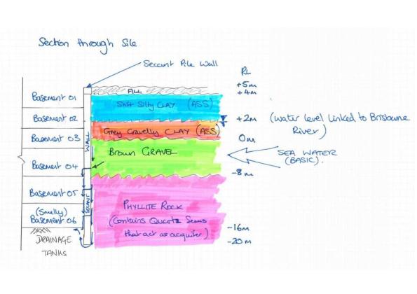
What I think is happening behind the wall (Not a flow net!)
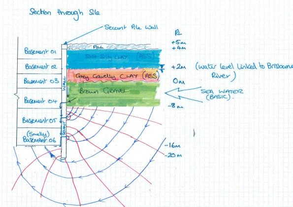
A less than perfect flow net.
However, the soil outside of our site has not been excavated and therefore cannot have been oxidised. The site is approximately 200 m from the Brisbane River to the North and the West. As you can see from my diagram the area is flushed by sea water with the tide . Sea Water is naturally basic and so counteracts any effect of the ASS. When I last had the water tested to get approval for discharge into the stormwater drainage the water was mildly alkaline and similar to the pH of the Brisbane River. SO NO IT’S NOT MY ASS!
What are we doing about it:
I now have to hold a workshop with the blokes to explain that it is not gas or ASS in the meantime the guys are cleaning up the walls to remove any mould (although there is no mould officially there) and remove the stagnant water that is on site. We are installing some temporary fans to move the air around the basement until the permanent fans are installed.
Mechanical affecting the structural
I had a rather enlightening conversation a few weeks back and I thought it was time I finally got my act into gear to blog about it – and it is to do with lifts, or more specifically lift shafts.
Australia 108 will be 100 levels, 319m tall. This will present two significant issues with the serviceability of the lift shafts:
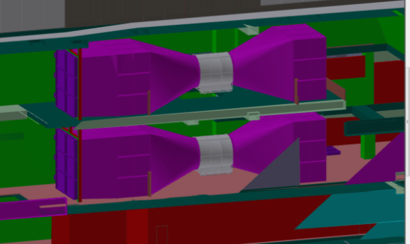
- Chimney stack effect. The temperature difference between the base of the building and the top of the building will be sufficient to induce an air flow up the lift shafts as the warm air at the bottom rises to the top (see Figure 1). Air is introduced at the base of the lift shaft by being sucked in though the lift doors, creating two undesired effects; firstly, the lift doors will likely jam and secondly, a loud whistling sound (often referred to as a howling). There are two fundamental options to deal with this problem. Option A) prevent air being sucked into the shaft (not feasible) or Option B) let the air do what it wants to do but provide an alternative inlet. Surprisingly Option B was the preferred option and we are looking at putting 2No 850 x 1000mm penetrations into the base of each lift shaft. Without providing additional outlets at the top of the shaft, we are not encouraging an increase in additional air flow to what naturally wants to occur.

Figure 1. Chimney stack effect
2. Piston effect. Of the 10 lifts, 9 are in banks of 3 and the goods lift is stand alone in its own lift shaft. The design speed of the goods lift is 5m/s (slower than the remainder) and is of sufficient speed to create a piston-type affect of driving air either up or down depending on the direction of the lift car. The displaced air moves around the car at a quicker speed sometimes twice that of the car (see Figure 2) creating undesirable vibration and noise. The effect is worse at the top, bottom and middle of the shaft (where the counter weights pass the car). To mitigate these issues, the cars will be made more aerodynamic and a 1000 x 2000mm penetration will be punched into the core walls at a low, middle and high level.

Figure 2. Piston effect
Prima Pearl is a 67 story building that that was completed in Jun 14 by the same management team as A108. The additional penetrations were not build into the core walls and have since had to be retro fitted to deal with the defects. Prima is 2/3 the height of A108.
Adding in air-relief penetrations seems like a good fix until you consider these penetrations were not taken into account on the initial design. In addition to these penetrations, there are also penetrations for the core crane, the hoist, two jump lifts, the jump form as well as embedded power conduit, water, waste water and sewer pipes that also, were not taken into account on the initial design. This is one core that is working extremely hard.
So what….think the design through to the finish throughout all stages of the life cycle and consult SME contractors to reduce the risk of missing critical elements of the design. This is not something I would have even thought to consider. The structural engineers are still struggling to make the core work in the serviceability state and every additional penetration makes this task that much harder.
Contract vs Common Sense
Over the last few weeks the tunnel ventilation team have been battling the Bond Street Station (BOS) prime contractors on the captivating topic of ‘floor screed’. I think that this is a good example of working to contract rather than common sense… one of many examples on site.
The station design includes a non-structural screed finish to the plant room floors. The main items installed in these rooms are the permanent vent fans, weighing 9 tonnes each. The fans will be in situ for a design life of 25 years, and impose horizontal (thrust) and vibration loads onto the structure through floor fixings.
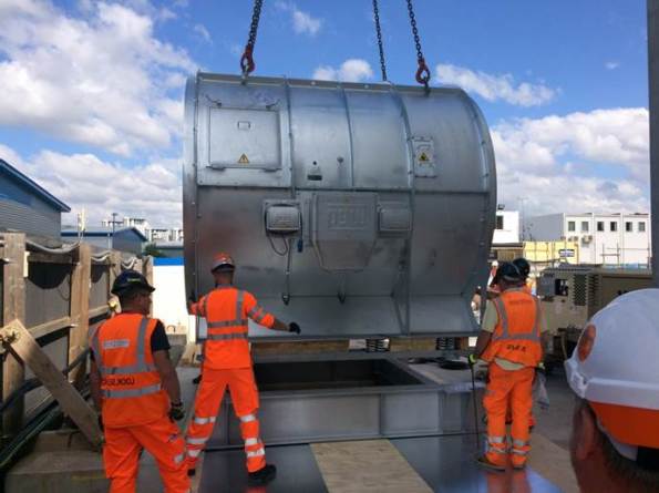
Tunnel vent fan (Horizontal Installation)
Graphic of the fan installation at Bond Street. The peach-coloured floor is currently being covered in a non-structural screed.
It doesn’t take a civil engineer to see that a non-structural screed will not stand up to this punishment for the station design life. However, despite numerous meetings pointing out the issue the station is carrying on regardless, and this week poured the screed for the plant room floor.
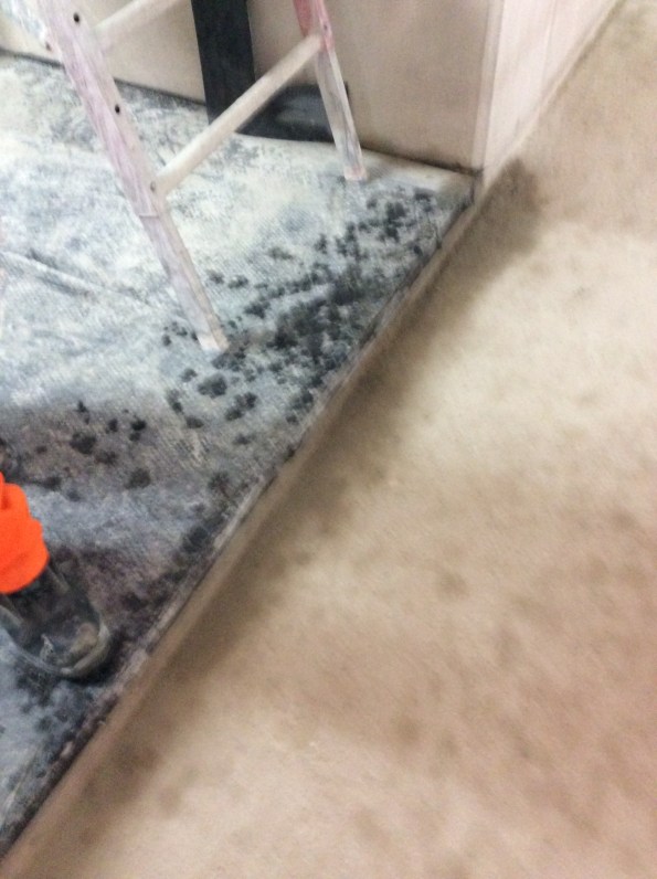
Image of the non-structural screed – note the lack of reinforcement. Please excuse the terrible image quality.
Why is the Bond St station working like this? A few theories:
- The contract incentives are linked to a finished room spec. It is easier to re-work than change the contract, as the commercial department works at a glacial pace.
- It is a lot of effort to search out the information on tunnel vent equipment, and involves liaison with my team. It is easier to claim ignorance, throw the screed finish in and then get money from the client (read taxpayer) to sort it out afterwards.
- The station construction is currently running with about 4 months delay; being instructed to strip-out finished work gives them a solid ‘arse covering’ excuse with the client.
The main contractors are rigidly working to the contract, and the client is unable to co-ordinate all of the separate designs and interfaces between contractors due to the sheer volume of work. I don’t think the client is innocent in all of this, they are slow at issuing instructions and slow at issuing notices to stop.
I expect they will be taking a concrete saw to the brand new floor covering in the middle of next week. Welcome to Crossrail.
Makes you wish you had volunteered for submarines!
I have just returned from an awesome week away with the family in Noosa. However, today reality has hit hard.
We have rapidly built our way out of the basement and have reached basement level 2 just underneath the props. Now that the permanent structure was in at B2 – B6, it was time to start removing the props that were used to support the basement. The culmination of nearly 3 months planning was coming to fruition.
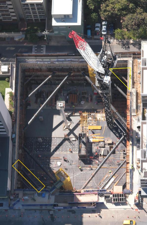
Old aerial photo of the site (highlighted area props to be removed, North is up).
I started my checklist:
- Cylinder crush results above 25 MPa – check
- Slab over 3 days old-check
- Exclusion zones in place – check
- Construction Union on side – check
- Actions and loads – check
- Risk assessment complete – check
- Access way in place – check
- Agreement from designers – check
- Confirmation that slab is in place from the structural site engineer – check
- Risk/Issue registers reviewed – check
- Final walk around and confirmation…

SW Corner – A big hole where a slab should be
Someone hadn’t built the stairs! (North is left)
Things started to unravel pretty quickly when I discovered that the stair penetration had grown from 4 x 2.5 m to 7.8 x 10 m. I attempted to find out what capacity I had in the slab/secant pile wall/walers in order to avoid a 5 day delay but to no avail. Despite pressure from the management, I called off the demolition. This will now result in $150,000 in lost time and considerable extra work. I now need to supervise the closing of this penetration and the adjustment of the programme.
Morals of the story
- Trust but verify! If I hadn’t checked up on other people this could have gone badly wrong.
- If there is a corner to be cut, people will cut it.
- Don’t assume that just because someone has been doing a job longer than you that they know what they are doing.
- Integrity, the pressure to crack on was extreme but, if in doubt don’t.
Where I would have rather been today…
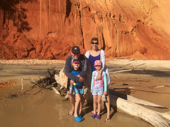
Great Sandy National Park- The sand cliffs behind were formed during the last ice age from blown sand dunes and are a great place to study slope stability of coarse grained soils. The rusty colour comes from the oxidation of the Iron in the sand (Can I claim this trip on JPA now?)
‘ealth and Safety gone mad
I am trying to complete the mountain of paperwork required to get permission for a sub-contractor to start on site. One of the checks is to ensure that the workers have valid medical certificates to operate safety-critical plant equipment. Anyway these medicals are valid for 3 years but some Health and Safety ‘ninjas’ on my project have stipulated that all medicals must have been completed within three months of starting on site. the subbies I am working with all have certificates that will be 3.5 months old upon starting.
So quite rightly the sub-contractor has challenged this requirement since if this was the case on all sites, then companies would have to have their workers examined up to fours times a year – 8 times more often than an airline pilot! This would also incur additional, unnecessary cost that will inevitably be passed onto the Client.
So I challenged this rule and asked whether it is based on any form of science i.e has research shown that those with a recent certificate have less sick days. The answer was no – the decision was made during a meeting and the figure of 3-months was plucked out of thin air and agreed upon.
You may be able to tell that I am finding this kind of ‘golden plating’ frustrating and so try to challenge it wherever possible.

Anyway, after challenging this with the health and safety team, I have secured approval for the subbies to start on site.
Has anyone else come across similar examples of the H&S Team unnecessarily gold plating the H&S regulations without any fact or logical reasoning behind it?
“Erm, the Grab is stuck!”
I was in the process on drafting a general update on the progress on site but late on Friday the piling sub-contractor’s world started caving in and it dragged me in. On Friday at 1900 (perfect timing like all great catastrophes) I, with the Project managers for FLO and Cementation Skanska were scratching our helmets, one of the diaphragm wall grabs was stuck at 60m. The situation worked itself out in the end but at the time, all options seemed bleak.
The background
The grab first got stuck at a depth of 60.5m depth around 1300. This meant it had 0.5m left to dig before the sub contractor long weekend. Either before or in the process of trying to release the grab, the rig had a hydraulic failure and lost 50 litres of hydraulic fluid. At this point it was hoped that the hydraulic failure was the reason it was stuck.
Unfortunately after the endless calls to Germany, diagnostic and repair the grab was still stuck. Shock loading and constant load of 42 tonnes for 3 hours didn’t work. The rig is about 160 tonnes on crawler tracks. The grab itself weighs 20 tonnes and is about 10m long. The lifting cables are rated to 100 tonnes.
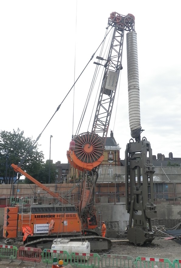
The diaphragm wall rig and grab unstuck
Options
As we stood around the rig in the quiet site we discussed three options.
1/ Use a 100t crawler crane and get it as close as possible. Then wrap a lifting chain around the cable and use both to lift together. This should add about 15t in addition to the rig.
Risks: very high risk activity using a crane to do something it isn’t designed for. Requires lift plans, method statements. The connection of chains to cables isn’t normal practice (shackles were not an option). Any slip in the cable could cause a potential collapse onto Battersea Park Road.
Impact to project: Least impact on rig if recoverable.
2/ Pay out as much cable as possible and cut all the cables and hydraulic lines from the grab. Then fix the cables through an anchor block to two100t cranes. Use both cranes to lift in tandem to get the grab unstuck, and in turns bring the grab to the surface.
Risks: very similar high risk activity using a crane to do something it isn’t designed for. Requires lift plans, method statements. Additionally
Impact to project: It would take a week or two to re-condition the grab and reconnect with new cables and lines. Lost time to project.
3/ If all else fails, cut the cables and hydraulic lines and bury the grab.
Risks: Safest in terms of H+S.
Impact to project: Despite the significant cost (£350,000) more critically it would take a long time (months) to find another grab. This would have massive effects on the project.
As we left it on Friday evening, the plan was to spend Saturday completing the necessary paper work and risk assessments to prep for option 1 and if not attempt option 2. The site was open on Sunday which suited as it would be quiet. In the end on Saturday morning the sub-contractor re-programmed or ‘re-baselined’ the software on the rig essentially telling it that it had a shorter jib allowing it to pull harder. It worked…
Why?
Now that the storm has passed there doesn’t seem to be any effort into working out why this happened. I calculated that at the depth that the grab was at, that the bottom 5m was in Thanet Sands. These are fine granular sands that are very hard (SPT tests gave an N value above 50, during some borehole testing we did across the site). I assumed that if stuck in the sands that the ground would tighten with time. or that continued pulls would only make the situation worse.
Has anyone seen anything like this before? We were lucky in this case as all the options presented significant risks. I never got to review the method statement or see the lift plan but if something had gone wrong I don’t know if the measures would have justified the risks.
Apparently Skanska got a grab stuck whilst in the Netherlands. Apparently the Belgian PC was preparing to send divers into the bentonite!!!
On a different note. The first bit of TBM has started arriving onsite.
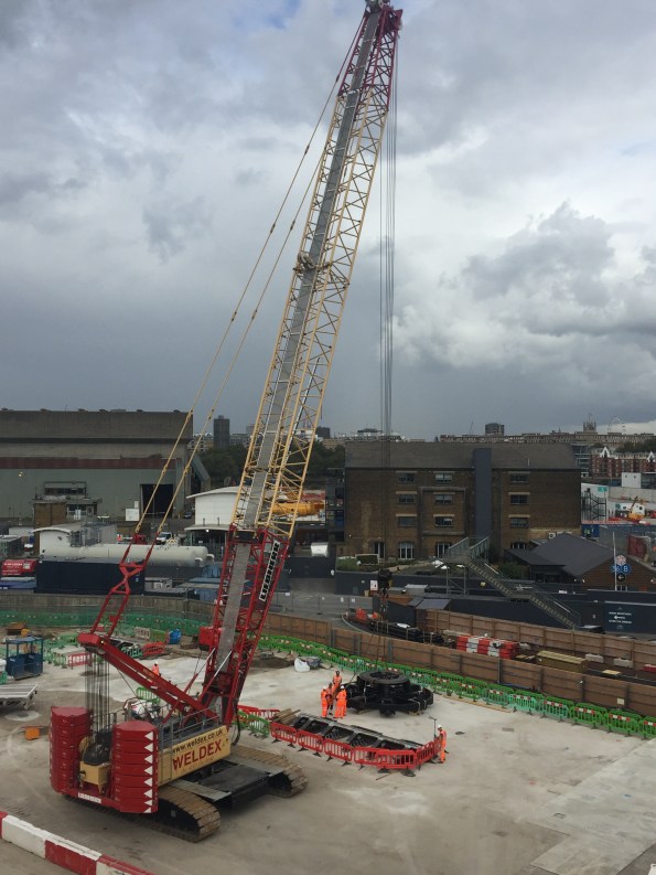
Cutter head number 1 and the 250t crawler crane to unload the TBM bits as they arrive
