Archive
Digital Twins
I first heard the term “Digital Twin” at a John Holland (JH) Engineers’ Forum. It was pitched as a new and exciting concept which would innovate the way JH would manage construction projects in future. After some research into the topic, I found that the Centre for Digital Built Britain is implementing a National Digital Twin programme which may be of interest to those heading for professional review soon.
What is a Digital Twin?
Digital twins are virtual models of a physical asset but, unlike BIM, they are digitally connected to their physical counterpart. Digital twins have been used for years in manufacturing and aviation but are beginning to emerge in the built environment. “Twins” are a concept, rather than a single piece of software. The Twin is created by continuously learning from multiple sources including analytics, machine-learning algorithms and artificial intelligence. Real-world data is captured via sensors, drones and other wireless technology operating within the physical asset which feeds back to the Twin.
Types of Digital Twins
Similar to the levels of BIM, there are levels of Digital Twin maturity which can be implemented as follows:
Level 1: Descriptive Twin. The descriptive twin is a visual replica with live, editable design and construction data, including 3D models and BIM.
Level 2: Informative Twin. The informative twin uses increased integration with sensors and operations data for insights at any given time.
Level 3: Predictive Twin. The predictive twin captures real-time data, contextual data, and analytics to identify potential issues.
Level 4: Comprehensive Twin. The comprehensive twin leverages advanced modelling and simulation for potential future scenarios as well as prescriptive analytics and recommendations.
Level 5: Autonomous Twin. The autonomous twin has the ability to learn and make decisions through artificial intelligence, while using advanced algorithms for simulation and 3D visualization.
Video 1: What is a Digital Twin? (from Redshift by Autodesk)
What is the National Digital Twin (NDT) programme?
The NDT programme is run by the Centre for Digital Built Britain (CDBB), a partnership between the University of Cambridge and the Department for Business, Energy and Industrial Strategy. The programme aims to:
1. Enable a National Digital Twin: an ecosystem of connected digital twins to foster better outcomes from our built environment.
2. Deliver an Information Management Framework: to ensure secure resilient data sharing and effective information management.
3. Align a Digital Framework Task Group: to provide coordination and alignment among key players.
Video 2: What is the National Digital Twin (NDT)? (from CDBB)
The NDT Gemini Principles
The CDBB has developed the “Gemini Principles” as the conscience of the NDT. The Gemini Principles consist of 9 guiding values to ensure the Digital Twins have purpose, maintain trust and function effectively. Find out more about the 9 values here: https://youtu.be/GoIv5ritEiM
Why use a Digital Twin?
- Improves efficiency and quality. Digital Twins allow the user to gain valuable insights about the performance, operation or profitability of a project, whether completed or in progress which can improve efficiency and quality.
- Aids decision making. A Digital Twin can provide real-time information about what is happening now which improves the speed of issue detection and resolution ultimatelyaiding decision making.
- Reduces risk. Conducting virtual inspections, using wireless technology, allows for identification of maintenance requirements or fault detection without requiring a human to physically inspect the asset. This is particularly useful for railways and large bridges and a technology driven inspection can return information not visible to the human eye. Virtual inspections reduce the requirement and risk for workers on a job site and can be much quicker; allowing for more frequent inspections which again reduces risk.
- Increases profitability. If the Digital Twin is fully engaged with for all of its benefits, a project can experience improved efficiency, quality and reduced risk which all provide the opportunity for increased project profitability.
- Enhances coordination. Digital twins enhance coordination as the real-time data capture can be combined with the proposal of a future installation or change concept and easily demonstrated visually to stakeholders, such as within a 3D model simulation. This provides an accurate prediction of how the asset will react to change and provides reassurance of the predicted outcome, enhancing coordination between the current physical asset and implementation of alterations.
- Provides reassurance of asset integrity. Digital twins provide a consistent and easy way to conduct real-time monitoring of a built asset which provides early warning of asset fatigue and potential failure.
Challenges of creating a digital twin
- Additional technology. The technological requirements to establish a digital twin are additional to those implemented for BIM. Companies will have to invest in Digital Twin technologies, train staff and maintain currency to effectively implement the concept.
- Return on investment not guaranteed. Unless an effective Digital Twin is implemented and then used to enhance the project, the return on investment will not be achieved. The upfront cost of technologies may require multiple project Digital Twins to be implemented before a profit is realised.
- Demand. JH are committed to making this investment and realising the benefits of Digital Twins as soon as possible, but other companies may not have this mindset. Unless a Client requires a Digital Twin for use in the operational life-cycle and beyond, some construction companies may not see the need or cost benefit of implement this concept.
- Coordination between creator and user. The creator of the Digital Twin during the design and construction phase may not be the same individual who uses the Twin for analysis of the asset in future. This disconnect could lead to a lack of investment in or understanding of the Twin and a poor replication of the physical world.
Innovative Digital Twin Data Capture in Practice
Video 3: ‘Spot’ the Robot Dog captures data for a Digital Twin (from DeZeen for Foster & Partners)
Additional Information
If you’d like to read further into this topic, I found these pages of interest:
National Digital Twin Programme | Centre for Digital Built Britain (cam.ac.uk)
Digital Twins in Construction, Engineering, & Architecture | Autodesk
What Is a Digital Twin? – Digital Builder (autodesk.com)
Digital Twinfrastructure | Institution of Civil Engineers (ice.org.uk)
Defining the digital twin: 7 essential steps | Institution of Civil Engineers (ice.org.uk)
Construction methodology, critical for health and safety.
Earlier this month I found myself in the unenviable and quite unpopular position in the site office of stopping works on part of our scheme after raising health and safety concerns with the general foreman. Thankfully he could see my concerns once I explained the problem and we implemented remedial measures to rectify the issue; what was more concerning was the senior engineer on site could not appreciate the significance of the situation and the risks posed to the workforce. I have attempted to outline the engineering problem below, but in essence we had to extend a cofferdam which required changing the existing singularly propped solution to a cantilever solution. The construction methodology was critical to making these changes safely and I was presented with the scenario I discuss after taking a few days leave and had to raise my concerns when I returned to site.
For my Phase 2 attachment I have been working on the Stokesley Flood Alleviation Scheme (FAS) with the Environment Agency acting as the Client. The scheme is split over several sites spanning 5km linearly along the River Leven flowing through Stokesley, a flood diversion channel and Eller Beck and makes extensive use of various temporary works. The package of works I write about here is known on site as the ‘Downstream’ works and consists of a reinforced concrete flow control structure constructed in the bed of the River Leven (flowing north to south) at the confluence with Eller Beck (flowing north east to south west); schematic shown in image 1. When I arrived on site in March the inlet structure to the north and 3 of 6 pre-cast box culvert sections had been constructed. The construction of a cofferdam, outlined in red, was required to complete the outlet structure and remaining culvert sections.
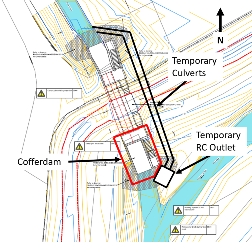
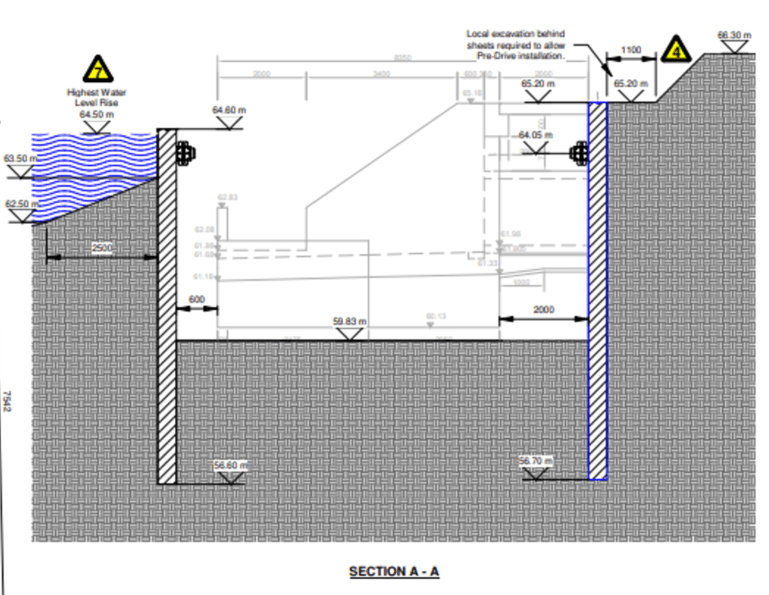
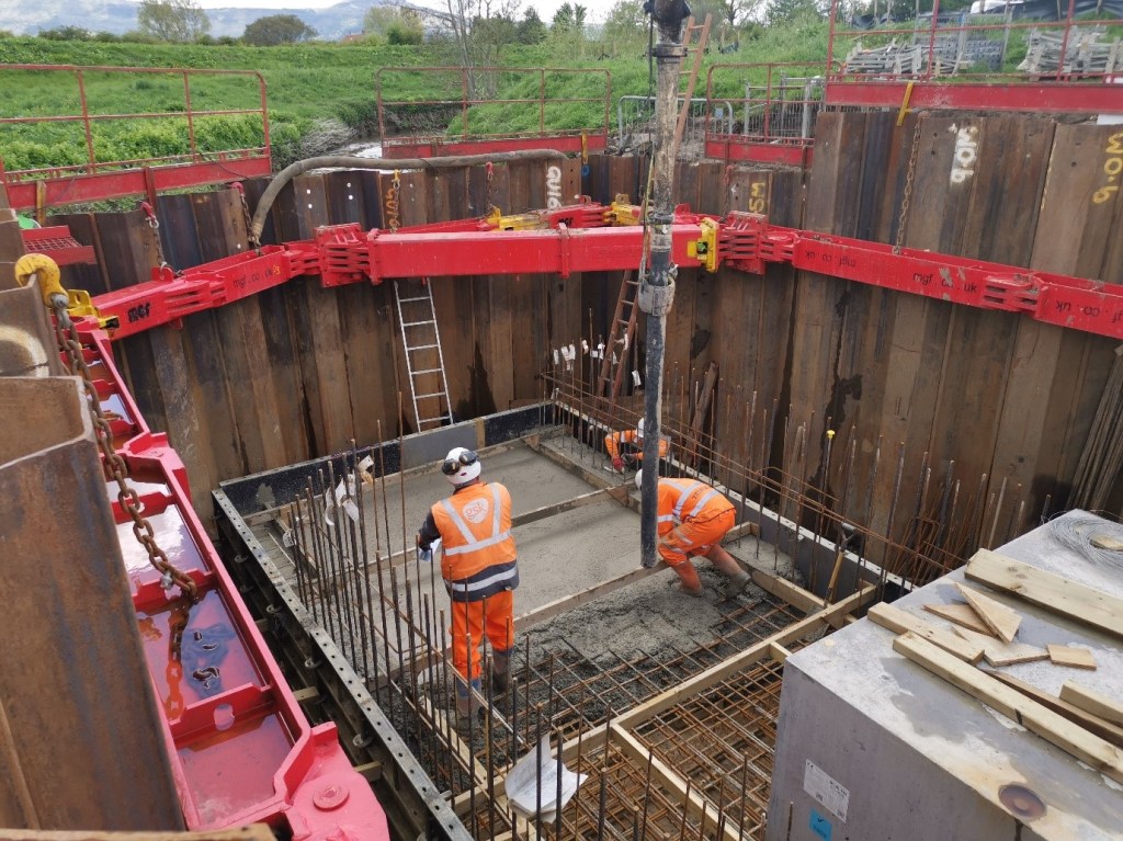
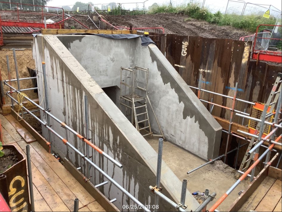
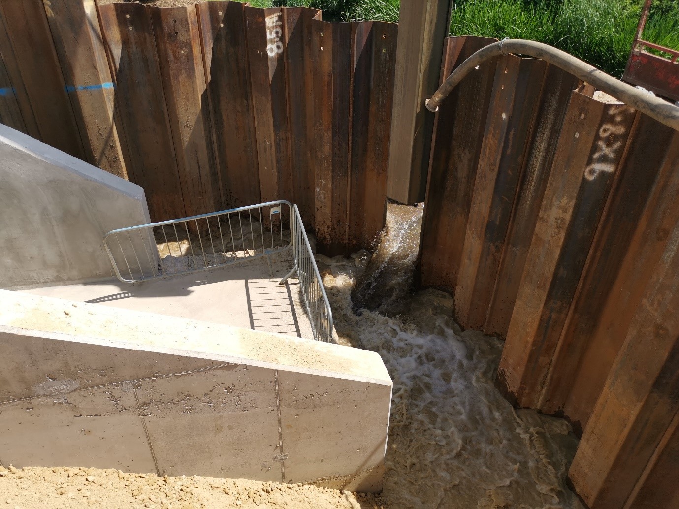
The original temporary works design (TWD) was provided by the specialist temporary works contractor MGF, images 2 and 3; this consisted of a combination of 8.5m (blue in plan view) and 8.0m (black in plan view) GU16N sheet piles. Image 4 shows the original cofferdam design on site during the concrete pour of the outlet structure apron apron. The worst case lateral pressure has a top of pile (TOP) at 65.20m AOD, prop at 64.05m AOD, dredge level at 59.83m AOD and toe depth at 56.70 m AOD (although actually at 56.20m AOD as 9.0m piles were delivered); therefore a singularly propped solution with a retained height of 5.37m and embedment depth of 3.63m. The lateral pressure on the southern face was modelled with a reasonable worst case flood level of 64.50m AOD and a TOP of 64.60m AOD specified (why a uniform solution with one pile length was not provided is a separate discussion).

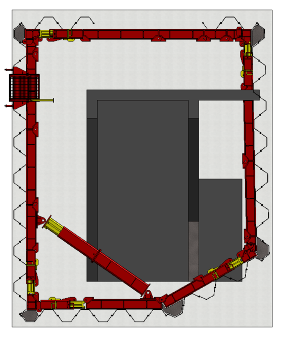
Due to the placement of the temporary outlet structure for the temporary twin culverts, image 1, which was necessary for bypassing the flow of the River Leven, the south eastern face of the cofferdam was constructed at an angle to prevent clashing with the structure. The issue this presents is the south eastern face of the cofferdam now clashes with the mass pour concrete base for the access stairway, an issue that could have been prevented with early planning and 3D modelling but is not expanded upon here. Image 5 shows a plan view of my Revit model which presents the clash clearer. Therefore, an additional engineering solution was required to complete the works for the access stairway once the outlet structure was completed, this drove a TWD change request which I submitted along with a potential solution. A schematic showing the required changes is presented at image 6; remove half of the temporary concrete outlet and realign one of the temporary culverts (if this was completed in the first instance then we could have avoided the change entirely), the sheet piles indicated by the orange lines had to be removed so as not to clash with the concrete base and further sheet piles installed along the red lines to retain the eastern side of the excavation and the river to the south.
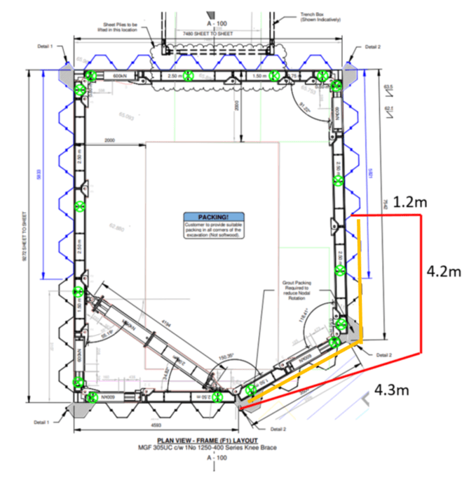
My proposal was to engineer a solution that would make the bracing frame redundant and allow the sheets piles to work in cantilever, noting the constraints of the length of pile and existing toe depth, then remove the frame prior to extracting the required piles. The proposed sheet piles could then be installed, again acting in cantilever, to provide the space required to complete the works. I perceived this as the most workable solution given the requirement and conducted a rapid assessment on Geo5 before sending the proposal to MGF. In short, the proposal was as follows;
- Backfill around the north and west of the outlet structure with 6N and compact to SHW 600 to a level that enabled the existing piles on those walls to work in cantilever.
- Excavate the active side of the eastern wall to a level that would again allow this wall to act in cantilever as the original dredge depth was required for the access stairway base.
- Model the river level as 63.30m AOD along the southern and south eastern walls (62.00m AOD has been typical for this time of year) and ensure the initial works are completed within one day when the river level is below this level. Again, this allows the walls to act in cantilever.
- Remove the bracing frame.
- Remove the piles specified (floods our works but is unavoidable).
- Either, install longer pile sections to act in cantilever to retain the original TOP level (MGF would need to specify) or install the existing piles along the new alignment to a new TOP level of 63.30m AOD.
Noting we would have to take risk that our works will flood at a reduced river level, the Sub-agent on site went with the later solution due to the additional time and cost of the first. I stressed to the site engineers that if this solution is approved the works must be completed within one day, in the specified sequence and when river levels are particularly low as we cannot take the risk on an overnight flood event above 63.30m AOD with the current TOP level and no bracing frame. Whilst I took leave Thurs to Mon that weekend, a TWD was provided by MGF with supporting calculations on the Thurs and this was approved by our TWD team on the Fri (BS 5975 specifies the level of checks required for different types of temporary works). Within the solution provided was the MGF construction methodology for carrying out the works which was the same as I outline above.
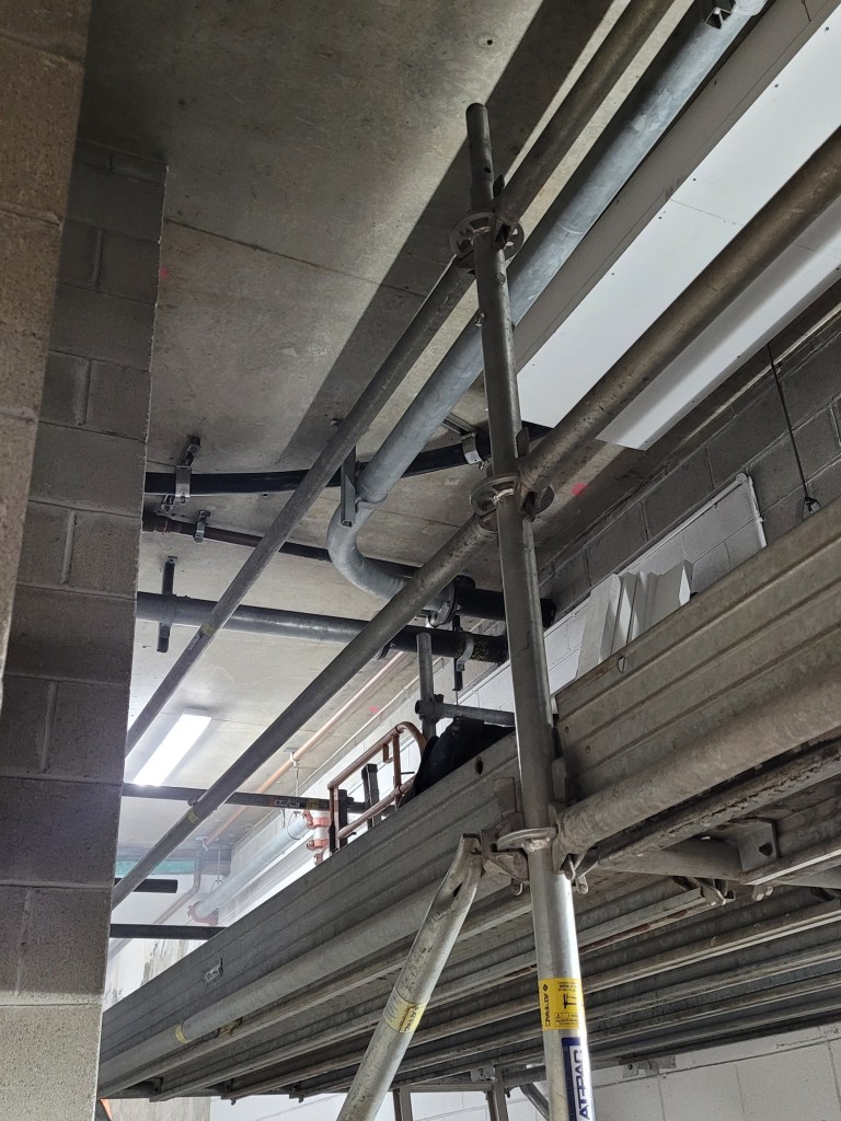
On the Tues I returned to site expecting to discuss the TWD, order the required piling rig and write the RAMS; unbeknown to me, on the Fri a temporary scaffold had been constructed inside the cofferdam and the frame removed, image 6. When I inspected the works, north and west of the outlet structure had been backfilled to the required level but the eastern and southern walls were still at the original TOP level and the active side of the eastern wall had not been excavated at all. We now had a situation whereby the retained height on the eastern wall was still 5.37m and the embedment depth was 3.63m (furthest wall in image 7) whilst the TWD solution specified a retained height 3.30m and embedment depth of 5.70m. The southern wall was still at the TOP level designed for a flood level of 64.50m AOD but was now only designed for a river level of 63.30m AOD.
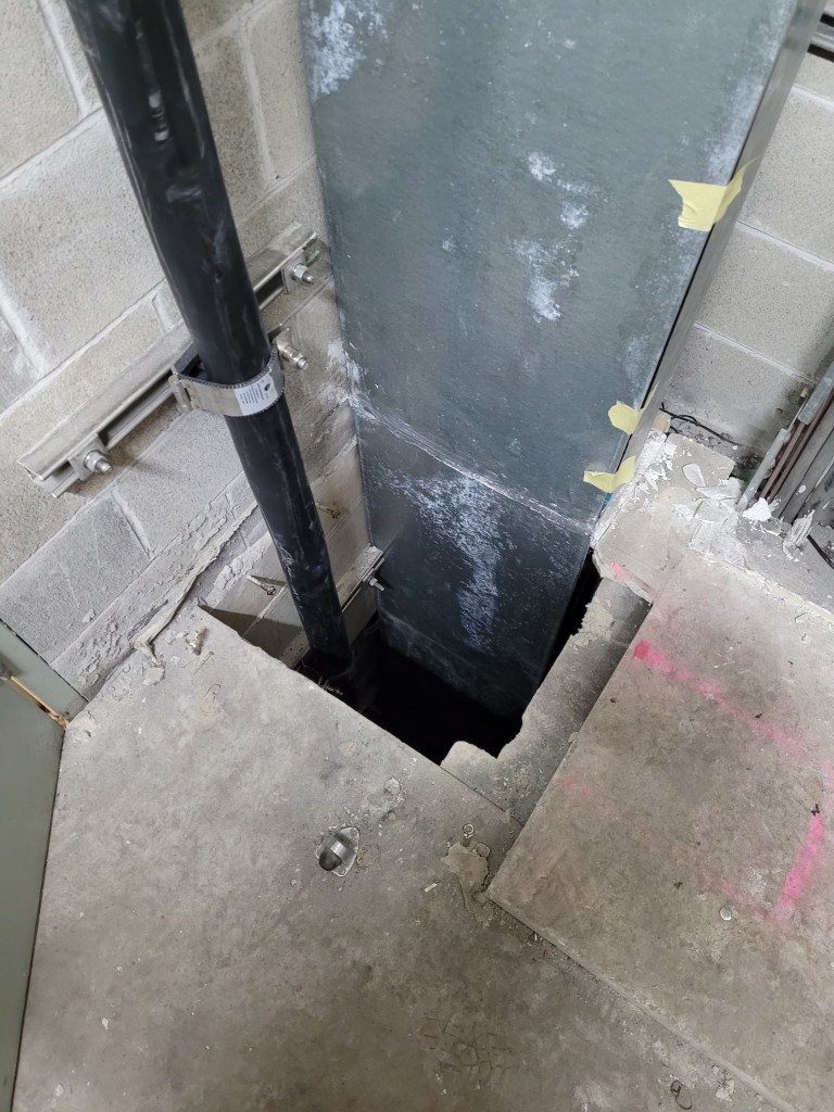
My first action was to clear the cofferdam of any members of the workforce and explain the risks we now faced to the site team; to my dismay one of the other engineers on site said it had been like that since Fri and so must be safe and we could excavate the eastern side whilst realigning the piles. Once I explained the MGF solution and construction methodology to the foreman we considered what remedial actions we could implement to rectify the situation. Obviously we could not put anyone back inside the cofferdam to reinstall the frame and we could not surcharge the eastern wall to drive the piles to the required level. We elected to pull one of the piles on the southern wall from the stable western side (image 8) and flood the cofferdam to minimise the risks of flood levels rising and increase the lateral pressure on the passive side slightly. We then positioned a 30t excavator at maximum reach from the eastern wall to excavate the active side until at the required level for the TWD; we were content that at this reach the excavator operator was at minimal risk from the wall failing due to the failure plane of the active earth pressure. Once safe, we then completed the remaining works in accordance with the TWD.
I wonder if anyone else has been exposed to a situation where a construction methodology has not been followed which has led to health and safety risks or where another engineer has not understood the overall engineering of temporary works which has increased the risks to the workforce. The concerning thing about this scenario is that work would have continued inside the cofferdam had I not been on site that day and the workforce were unknowingly put at risk when removing the frame four days prior.
Thank you, this is exactly what we wanted 10 years ago.
HS2 was proposed by government in 2009 and is now earmarked for completion in 2033 (partial completion 2026). The Shard opened in 2012, 9 years after gaining planning permission. Roadworks cost the UK economy £9 billion in 2016. The office type projects I’m working on are taking around 6 years from finalising a detailed project specification to taking possession. In February 2020, China built / assembled two hospitals (1000 & 1500 bed) in two weeks. A 2012 report noted that the Palace of Westminster was in urgent need of extensive restoration, this work is scheduled to start in 2025 and take 6 years. COVID will change everything / some things / nothing….
While project timelines and associated costs vary wildly, for many projects with moderate complexity a timeline of 10 years from conception and 6 years from specification with funding is reasonable. Such a project being completed now will have been conceived as the Arab Spring ushered improved living standards for the people of Libya, Egypt, Yemen, Syria, Bahrain, Iraq, Lebanon and Sudan. In 2010, the most popular electric vehicle was the Nissan leaf (73 mile range) which worked with the G-wiz (50 mile range) to show that electric cars would only every be driven by people who had given up on getting anywhere or were playing golf. The EU had supported nations struggling through the financial crisis showing the strength of the union while the Russian President had visited the White House for the first time showing a thawing in relations.
With so much changing between design and benefits realisation, it is not surprising that partial re-build or re-designs are often necessary in construction. Such a process involves wastage (labour, materials, equipment) while incurring disproportionate costs for additional work (short notice labour, materials, equipment + weak contract negotiating position). The delays incurred here also create a feedback loop due to further separation between benefit realisation and project specification. Watching this occur on my site with a simultaneous tender process going on for future buildings, it feels the incentives of most elements within the process are working against a more realistic design methodology which focuses on uncertainty.
Primarily construction projects are costly for business and often funded through debt. Convincing someone that a venture will be successful can be more about conviction and confidence than substance. The importance of a precise scope was highlighted during P1, but as is often the case, is there less focus on accuracy than precision? Would a scope which focuses on flexibility and uncertainty be seen as pragmatic or evidence of a party not sufficiently understanding the problem?
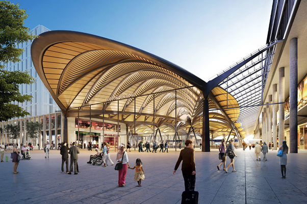
Design proposals are presented with 3D avatars from a future population, not as wire models or generic individuals to show scale, but as individuals of diverse abilities, goals and culture. These avatars move around with purpose (but not rushing) along optimally occupied but un-congested pathways. The below render of a future Euston Station has detailed a child’s shoe colour and will be presented along with a timeline and cost that most involved will expect to at least double. Clearly these renderings are not literal predictions of the future. I do however believe this is indicative of an industry which currently relies on both implicit and explicit over confidence in predictions.
Many aspects of construction (and large military projects) seem to rely on getting the ball rolling with the understanding that, once started, the inertia of sunk costs will keep things going. Contractors bid low hoping to make up the difference on changes, funding is approved on the most optimistic of cost estimates and “fluff” is delivered before a capability to prevent downscaling in response to spiralling costs.
This is the opposite of the highly successful AGILE project management methodology which broadly focuses on delivering a minimum viable product (most basic product that achieves the customer’s key requirement) and then iteratively improves it once the requirement has been clarified and confirmed. Coming primarily from software development, AGILE clearly isn’t fully applicable to construction but aspects of it can be brought across. Car parks can be built to allow for simple future vertical expansion, false floors / ceilings allow for rapid interior changes and modular / small scale power generation reduces the need to predict future demand.
Despite this, the construction industry seems outwardly to continually project that mistakes were made in the past but we’re now at the point when the lessons have been learnt so can predict with confidence. Has this been the experience of others? Do people have examples of projects efficiently changing throughout construction as the requirements clarify?
ATTRIBUTE 7 – Sustainable Development
Phase 4 (Civils) – As discussed.
Everyone else – if you see or hear anything that may be relevant to those sitting their Chartered Professional Review in September please post.
DS – if you fancy posting potential interview questions in the comments that would be helpful.
https://www.bbc.co.uk/news/world-europe-56716708
https://www.bbc.co.uk/news/av/uk-57756991
https://highways-news.com/councils-block-he-plans-to-infill-70-disused-railway-bridges-and-tunnels/
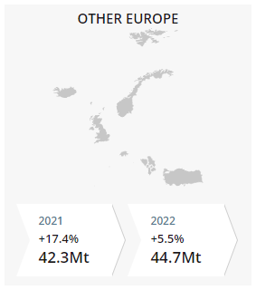
Supply vs Demand – how severe is the current material shortage?
With nearly half a million cases reported globally in the last 24 hours, coronavirus continues to present a direct health risk to many people across the world. Despite this, some countries including the UK are fortunate enough to be confident that they have seen the worst of the pandemic within their borders. As a result, much discussion in recent months has been focussed on recovery and getting life back to “normal”.
Across the world, many countries including China, The USA, France, Australia and The UK have announced significant infrastructure investment as we go forward into a “post-pandemic” world. This will lead to a rise in demand for basic construction materials such as steel, cement, timber and some plastics.
Supply chains have been stressed significantly over the past two years not only by restrictions to movement but by reduced outputs, political events such as Brexit and incidents like the blockage of the Suez Canal. Scarcity of construction materials is already beginning to take hold. For instance, on my site attachment, concerns over a shortage of steel fibre reinforcement (SFR) for sprayed concrete lining of a tunnel shaft are beginning to materialise.
Fortunately, we are able to revert to using steel mesh in lieu of the SFR for the most part but this is more time consuming to construct and leads to increased safety risks from additional working at height, more heavy crane lifts and hot works. What’s more is that a neighbouring team constructing a diaphragm wall on the same site is beginning to see shortage in availability of mesh which could scupper the contingency plan for the shaft.
If SFR and mesh stocks dry up, this situation has the potential to halt progress risking significant delays across the programme. One way of mitigating this might be to call upon the designers to revise specifications and offer alternatives to keep works going without too much increase in cost but the options are no doubt limited for a project that is already well under construction.
Time will tell if design change will be made necessary on my site, but it led me to wonder if anyone else had experienced materials shortages on their attachments (phase 2 or 3 – contractor or design house) and what might have been done to overcome the issue. Can anyone share some of their experience on this matter?
Modern Methods of Construction: manufactured meaning or assembled context?
Since starting on the PET course last year my general awareness of the construction industry has steadily increased and, like many who visit this blog, I have been exposed to new language and terminology. Much of this has resulted from interactions with PEW teaching staff, attachment experiences, and wider exposure to industry through professional development activities. Just like in the military, words and phrases develop meaning based on their context.
One such term that I have stumbled across multiple times is “modern methods of construction” (MMC). On the face of it, MMC is a relatively baggage-free phrase that could be used to describe any recently developed solution to contemporary construction challenges. This interpretation suggests no underlying connotation which is why I have never sought to understand any specific meaning until now.
Recently in my latest attempt at catching up with UK civil engineering news (albeit several months behind), I took some time to read the National Infrastructure Strategy (NIS) which was presented to Parliament in November 2020. In the document, MMC is used generically to lay emphasis on the idea that, to achieve the government’s production, sustainability, and development goals, we must use innovative construction solutions to combat modern-day infrastructure challenges. Late on in the document, MMC is identified as a means by which the government will encourage transformation in the construction industry defining it as “off-site manufacturing by standardising components, designs and interfaces”. This brief and fairly narrow definition provides a clue as to where the term MMC came into use within construction.
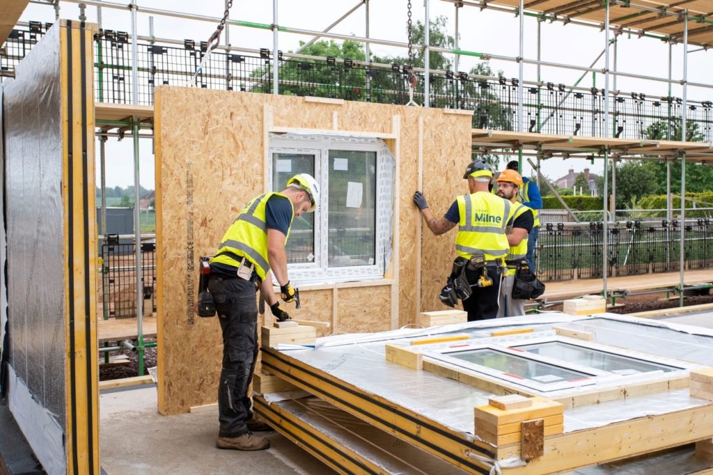
After some brief searching it became apparent to me that MMC saw a rise in use shortly after the turn of the millennium. This was a result of a 2005 National Audit Office report entitled “Using modern methods of construction to build homes more quickly and efficiently”. This early report defines MMC in terms of its products including the use of panels or volumetric modules produced in a controlled factory setting and assembled on site for the production of residential housing. In this context, MMC was proposed specifically as a way of meeting increasing housing demands against a backdrop of a stretched workforce. Effectively, it restyled existing methods (such as post-WW2 prefabrication) with an emphasis on volume and standardisation.
Going forward from 2005, the term continued to be used within this context but its meaning gradually broadened in the following decade as it was adopted across the construction industry and by policy makers. In the government’s Construction Playbook (Dec 2020), MMC is described as:
“a wide term, covering a range of offsite manufacturing and onsite techniques. MMC provides alternatives to traditional methods and has the potential to deliver significant improvements in productivity, efficiency and quality for both the construction industry and public sector.”

This suggests that MMC is a catch-all term for innovative construction methods that create a tangible difference across the Time-Cost-Quality triangle. Although this definition provides no explicit reference to the three pillars of sustainability, the accompanying description within the Playbook equates efficiency to delivering quality solutions with reduced greenhouse gas emission – a minor nod to global warming.
The Playbook’s requirement for MMC to benefit the construction industry (contractors, designers and suppliers) as well as the public sector (the client) makes it clear that the benefits shouldn’t just be for government. Despite this appearance of shared gain, the end-user, a critical stakeholder t be considered for project success, is at worst omitted and at best implied within the public sector.
Modern Methods of Construction as a term, therefore, does have a background and hidden meaning within our industry. Some will assume MMC relates specifically to off-site manufacture and on-site assembly of domestic housing however this interpretation is becoming dated. The term has been adopted more widely such that its meaning depends on the context and, as in the example of the Construction Playbook, is less specific in recent use.
Where then, does this lead us? It highlights the need to scratch beneath the surface, to broaden our contextual understanding and to be aware that phrases we use can be unexpectedly misinterpreted depending on our audience’s context. Furthermore, being able to identify short-comings in established definitions, such as the omission of end-users as beneficiaries of MMC in the Playbook definition, means that we are more likely to implement methods that contribute to outputs that suit their need.
Sustainability – Always an excuse
In preparation for my professional review I have been reflecting on how sustainability shapes the designs my colleagues and I have delivered over the last 6 months whilst working for a temporary works design consultancy (WHP).
There are a few ‘sustainability’ quick wins we have under our belt which anyone who has worked with temporary works would be able to reel out:
- We use proprietary equipment such a PERI pans and RMD Super Slims to reduce material usage because it can be reused.
- Rather than paying too much attention to the solution the Client’s TWC/TWS thinks they need, we focus on reviewing the Client’s problem to ensure the design we provide is the most economical solution. We often find that whatever the TWC has designed is over-kill and a more economical design can be provided.
- We are often able to use/re-use material that is already available on site (e.g. old ply wood used for hoarding, concrete legato blocks, scaffolding tubes etc).
However, if I’m to reflect truthfully (and cynically) I would say that the drivers for points 1 and 3 is often a matter of convenience for the Client with a sustainable side-effect. I also observed that the key driver for point 2 was more about offering value for money for the Client as a primary objective with a sustainable solution being a convenient side effect.
So why didn’t I sense that sustainability was a priority of temporary works design? I think it’s for the same reason that it isn’t whilst on military operations – the way we (or the Client) prioritises the Time/Cost/Quality triumvirate. The nature of temporary works means that it’s rarely considered sufficiently in advance for time not to be a constraint, and because cost is always a constraint then it’s quality (and consequently the solution’s sustainability) that suffers. If I reflect back to my time on HS2, the permanent works had a huge design team that had been developing our design for years and were under significant pressure to achieve sustainable goals. On the other hand our temporary works were often required yesterday in order that works weren’t delayed on site.
I’d be interested to know if any one else has identified the difference in emphasis on sustainability between permanent and temporary works?
Time vs Quality – 5 mins Read
Throughout construction projects we are continually reminded of the time, cost, quality conundrum. Other than relatively small military construction tasks, rarely have I experienced this compromise so evidently as in the example below. Conceptually, it makes complete sense that you cannot achieve all 3 at the same time; designers, engineers, construction managers must appropriately select the driving force and stick to that philosophy throughout all stages of project management.
During a recent weekend rail possession on the T8 Airport Line in Sydney I found it extremely obvious to identify the critical driving factor – TIME! During a rail possession, the train line completely shuts down and contractors across all industries are then able to safely access the track, whilst the public are ushered onto replacement buses at a cost of approx AUD $10 million for the weekend. Among a large number of tasks to be completed by various contractors, I was working as a site engineer for small core holing and cable pulling task in Green Square Station.
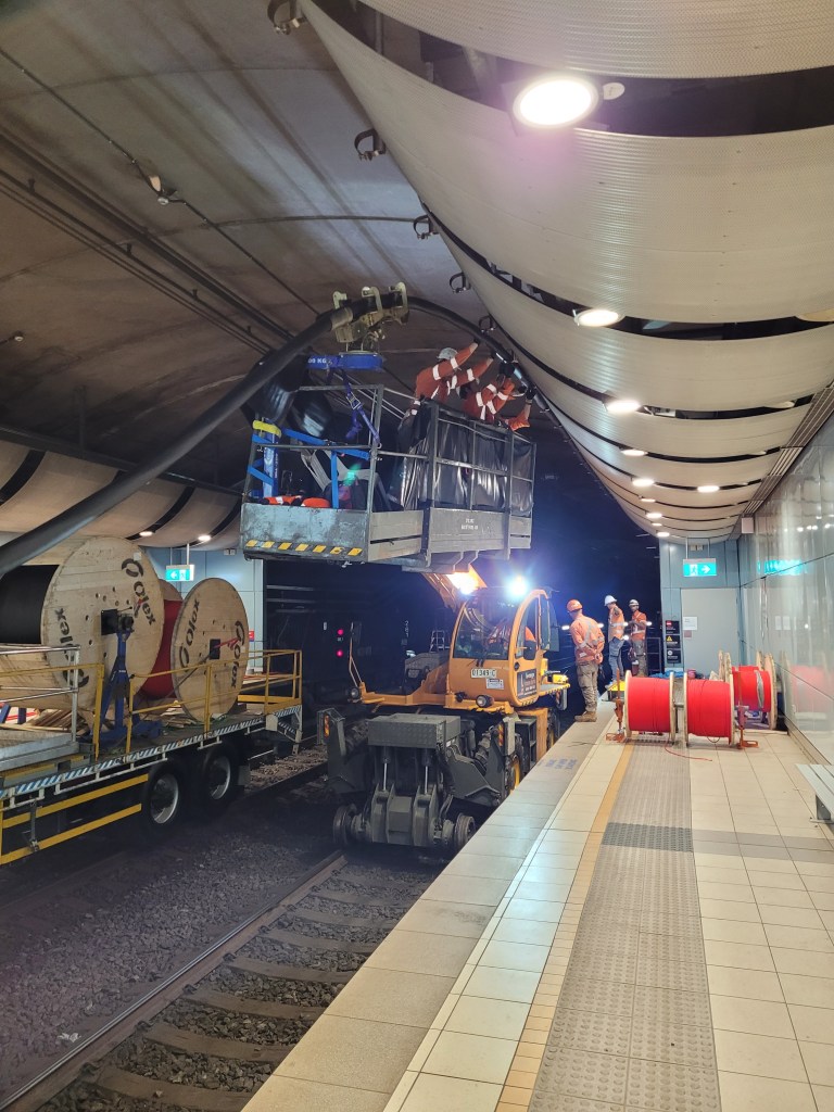
It was made clear to all staff and sub-contractors involved in the task, that the track and all stations needed to be handed back to Transport for New South Wales (TfNSW) at 02:00 on the Monday morning, ready for the Monday morning commuters. I would imagine the cost of not achieving this deadline was too large to comprehend and would cause a large headache for senior management!
Without compromising workplace health and safety, the clear goal was to complete the task by the deadline, at the expense of quality. On a number of occasions this was obvious to see….
The brackets were pre-positioned before the cable pull and therefore the 11kV cable could not be clipped into a few brackets along it’s length, in time – a clear example of a drop in quality/workmanship to achieve the deadline. Don’t panic, the brackets could be moved at a later date during normal station operation, as all the brackets were back-of-house.
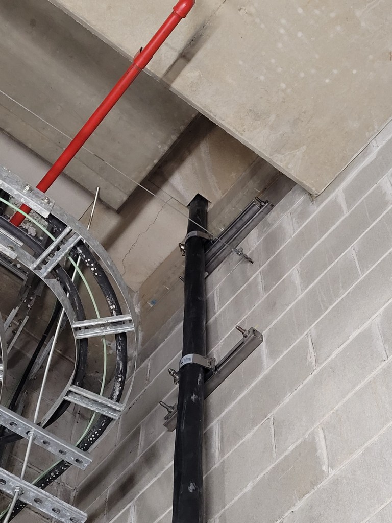
The 11kV cable weighs approx 15 kg/m and is relatively stiff which means it is a difficult cable to work with, especially when trying to bend the cable through various rooms and between multiple floors of the station. As shown in the images above, the result is that the cable pulling contractor scuff/mark the cable sheath as they work, in order to position it in accordance with the design. If required, cable jackets can be installed at a later date to repair any non conforming lengths of the cable. Just another example of a drop in quality to meet the deadline!
Flexible Working
Just wanted to start a discussion on how the construction industry will change as a result of Covid-19. Arup have just made a big announcement about global flexible working, 3 days in the office a week and flexible hours. Allowing employees to work their 7.5 hours a day when it suits them but facilitating crucial collaborative work with teams coming into the office. There are many pros and cons to flexi working but I quite like the idea of this mix and it will be interesting to see how it plays out. Some other thoughts on flexi working:
- Time in the office is really important for developing junior engineers.
- Companies that do not offer flexi working may loose out as people seek roles in companies with a flexi policy.
- Line management of individuals is key to ensure that work patterns meet team and project outcomes.
Another area of interest is how construction firms can adapt to offer roles to people with disabilities. I have conducted a site visit from the design office with a person who uses a walking cane. He drove to the visit and the whole site was accessible due to AliMak lifts between levels (it was a tunnel site) and a few stairs he could manage here and there, see image below. This is particularly pertinent for design offices where people are employed for their brains! He is an Associate Principal with 20 years experience and a technical leader in retaining structures. Arup have been named in the Valuable 500 a global movement putting disability on the business leadership agenda. A campaign to get 500 national and multinational, private sector corporations to be the tipping-point for change and help unlock the social and economic value of people living with disabilities across the world. Because the potential of 1.3 billion should not be ignored.
Arup makes flexible working permanent for UK staff | Construction Enquirer News
Drafting complex 3D structures – 2 min read
Building 3D models of bridges with complex geometries is beyond anything I can do in Revit. With varying curvatures in up to three dimensions it can take the bridge drafters a while to build the 3D models.
To do this the drafting team use a visual programming language which plugs in to 3D modelling software. To me the programming looks extremely complex but on a basic level appears pretty intuitive. Using this they are able to model the bridges. Importantly it allows different drafters (in separate countries) to quickly understand and update the models.
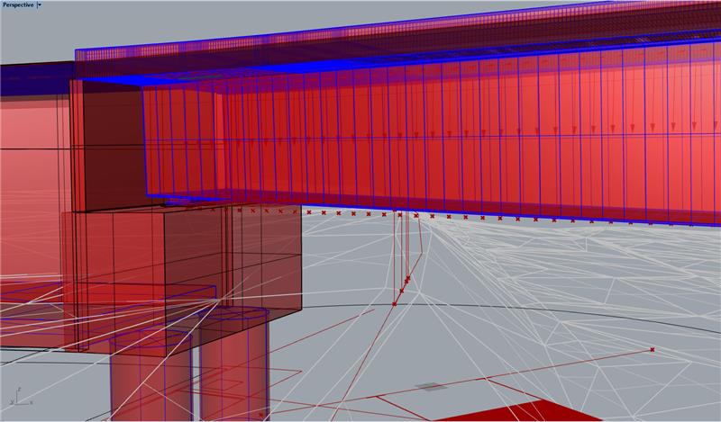
3D model of the bridge I have been working on. The soffit varies in a single dimension while the deck curvature varies in all three. 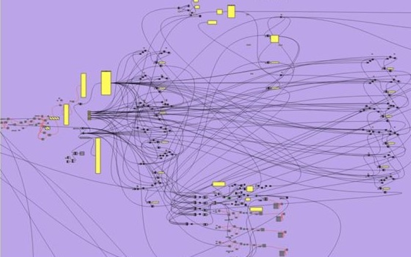
Screenshot of part of the visual programming language used by the drafting team to build a 3D model of the bridge. Software is Grasshopper. 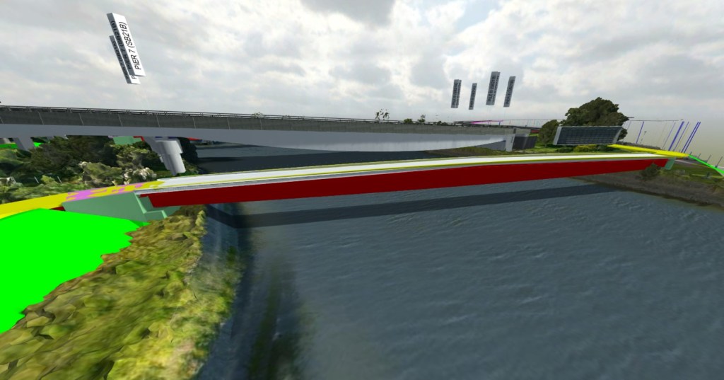
3D model imported into Revizto (BIM level 2)
The design consultant I have been attached to now exclusively use Revit on all building projects. However, the bridge team only use it on about half of the bridges with the other half being drafted in AutoCAD. Fundamentally though there isn’t much of a difference between the two. The Revit drafters use a DYNAMO visual programming language plugin while the AutoCAD drafters use Grasshopper 3D (visual programming language) and Rhino 3D (3D modelling software). With a lot of bridge drafting still done in 2D (cross bracing would take a long time to model in 3D) I can see why Revit has not been fully adopted. However, the bridge drafters believe that in 5-10 years they will be exclusively using Revit.
