Archive
Breaking Bad Brisbane Style
So its been a hell of week here at Brisbane Casino Towers. The local residents have been high as kites, from throwing objects out of their balconies, jumping on to mobile cranes, breaking into our sub-contractors offices and stealing their laptops and now finally they have been busted for running a meth lab!
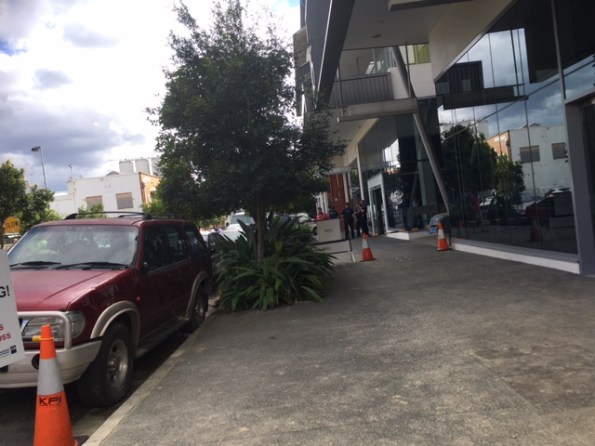 Brisbane’s finest displaying an interesting cordon.
In my last post I mentioned that I have been placed in charge of removing the temporary struts and ground anchors. Believe it or not we don’t have any software for 3 D mapping and given that the problem is a three dimensional one I produced this for my meeting:
Its all hi-tech at Brisbane Casino Towers. (The numbers relate to order of pours and it’s used to explain the load path of the slabs).
The removal of the supports is a nightmare and sums up the project really. The props are designed by ADG, the anchors by QPS, the permanent slabs by BGE and the wall by Franki Pile (now known as the WALLAPs for their worship of the false god WALLAP). For me it is a great opportunity that has drawn the attention of the Regional Director but I can’t help but, feel that they gave it to me because it is something of a mission impossible and they would probably have to sack someone if it goes wrong – (Neil/John TMR2 coming your way). Anyway the meeting went well, I ran it entirely and the 3 chartered engineers were pretty complementary. I will go into more detail later but, this is only the start of it.
Oh on a positive note the we all went to see Australia v England at the Suncorp  I’m sure Izzy is concerned about the English defence and not that I have confiscated the Haribo!
It’s not all about the bike…
I’m currently reflecting on the last 15 months living and working in Oz whilst exploring the vast bush of WA.
I’m about to start day three of a 10 day epic trail ride from Albany back to Perth following the infamous 1000km Munda Biddi trail.
So far the terrain is akin to the UK’s green rolling countryside complete with similar weather – very wet and windy!
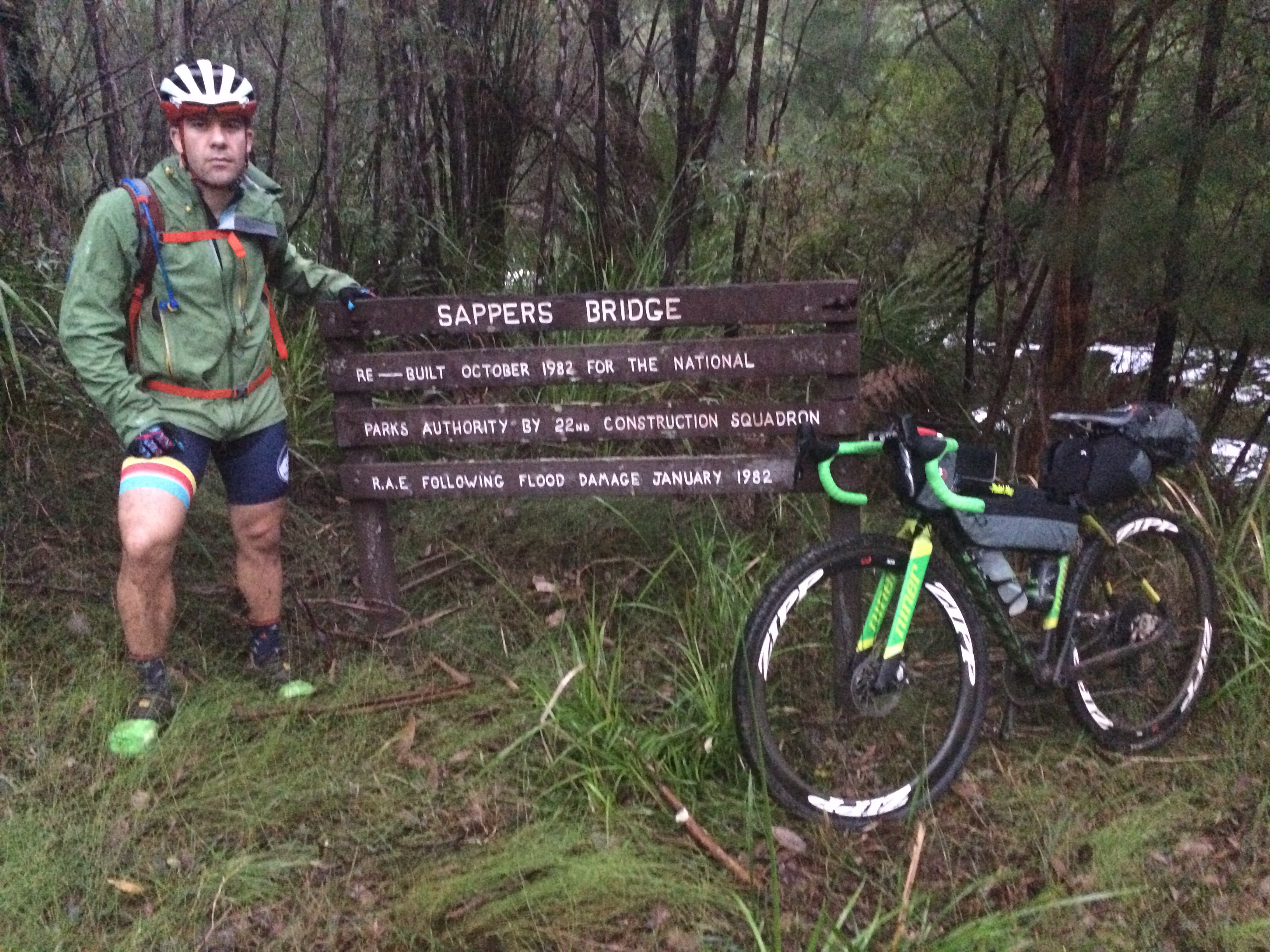
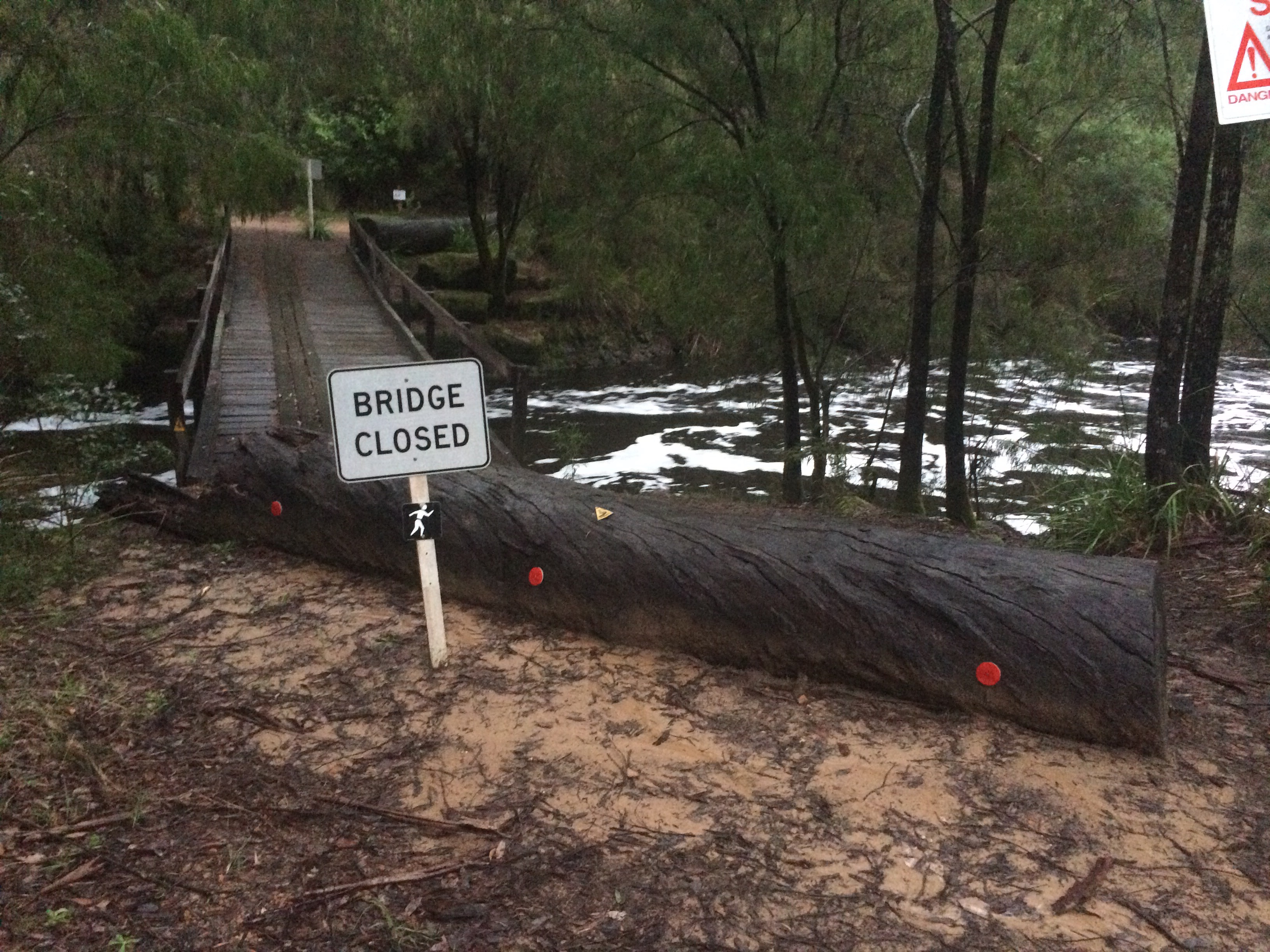
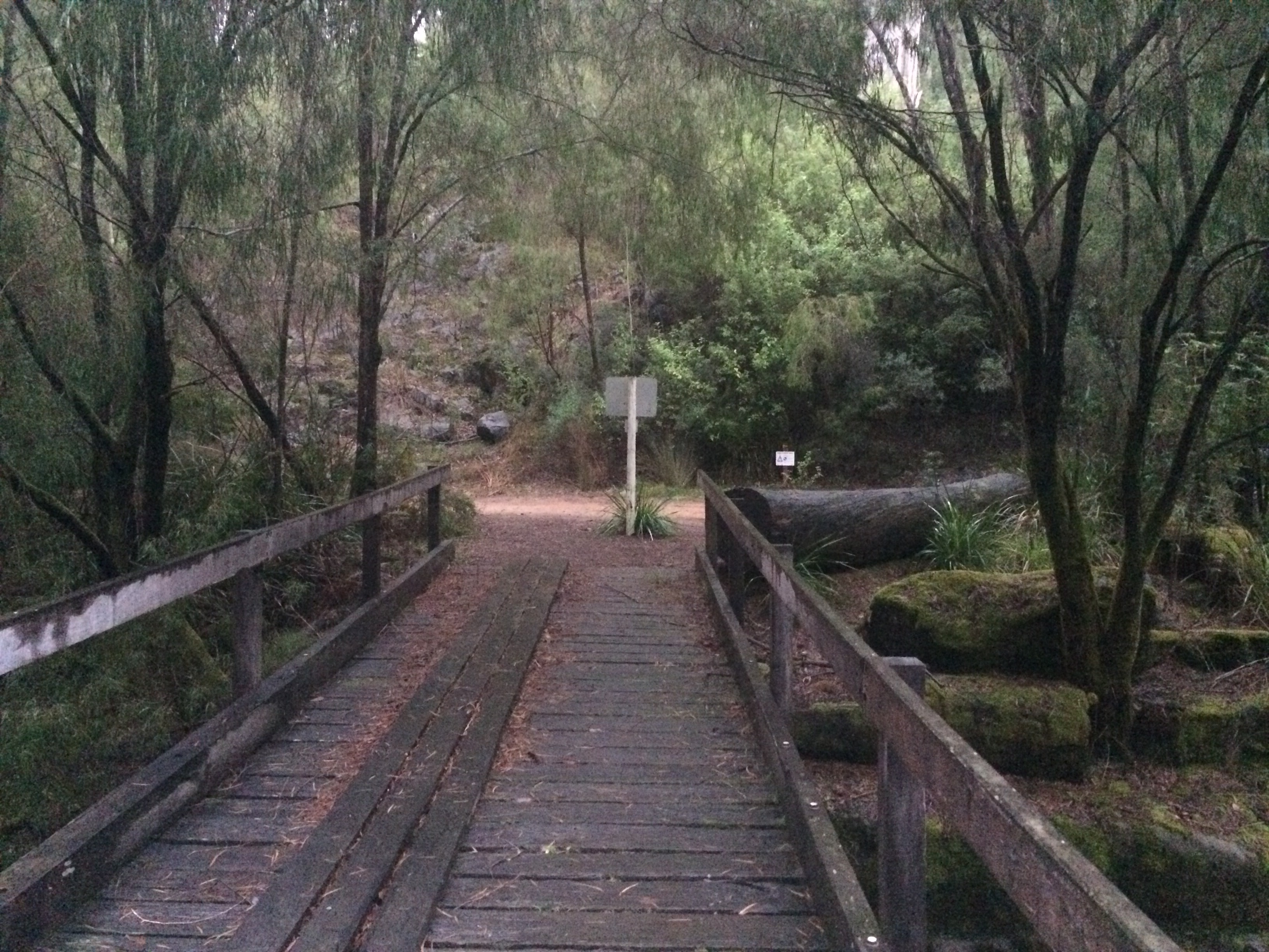
En route I have come across the more obscure Aussie road signs and Sappers Bridge.
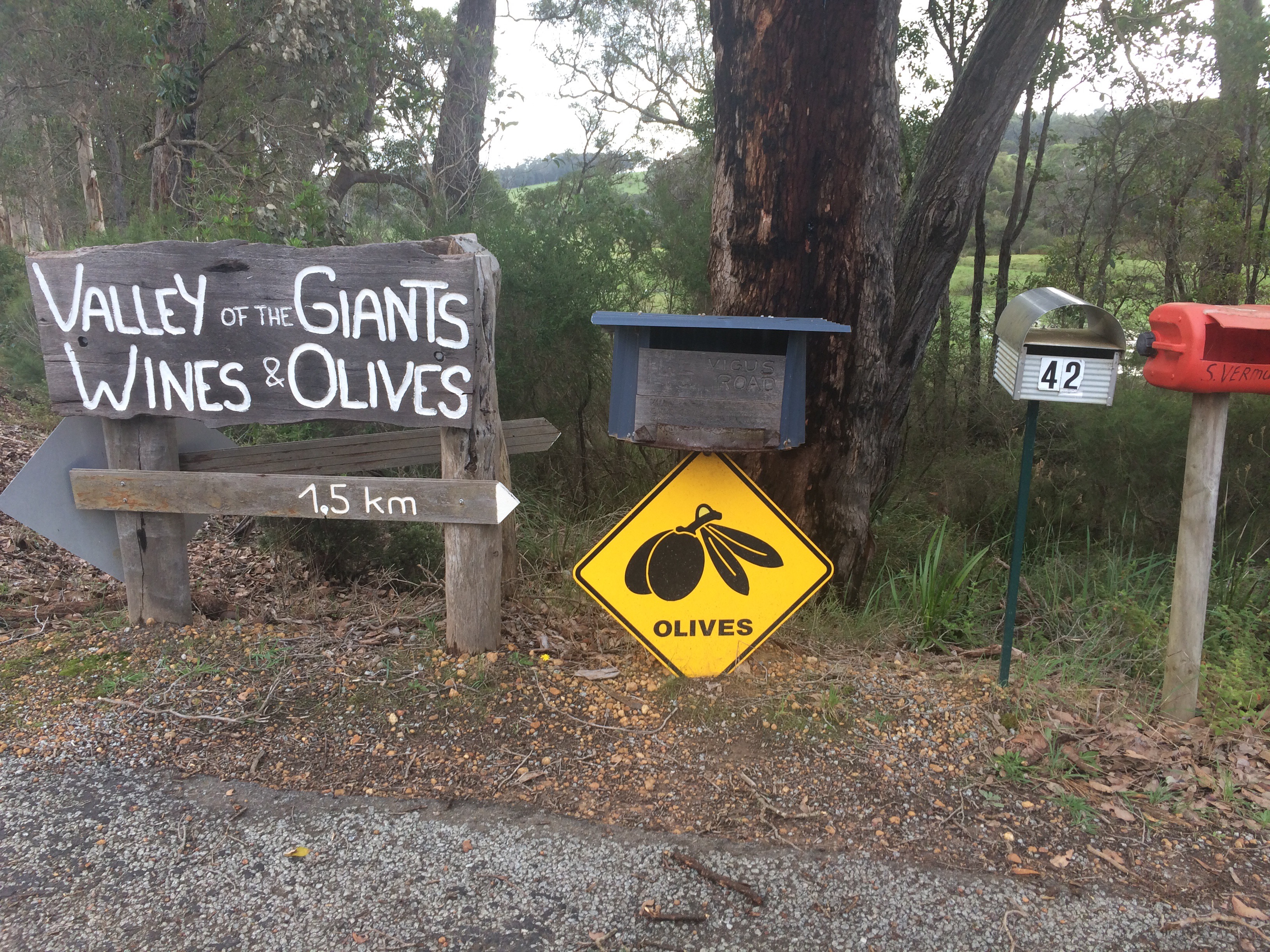

220km down with a couple of easier days ahead before the epic 167km day 5!
What’s that Skippy? Someone’s trapped down a well?
Well, well, well… I have often found myself taking one step forward and two back as a direct result of working alongside a heritage building. Several issues have arisen but this blog will focus on one – a 19th Century water well.
Given that we are working on an old brewery site, some distance from the nearest river, the existence of wells is to be expected. What is most frustrating with this recent issue however is its location, see Figure 1.
Figure 1.
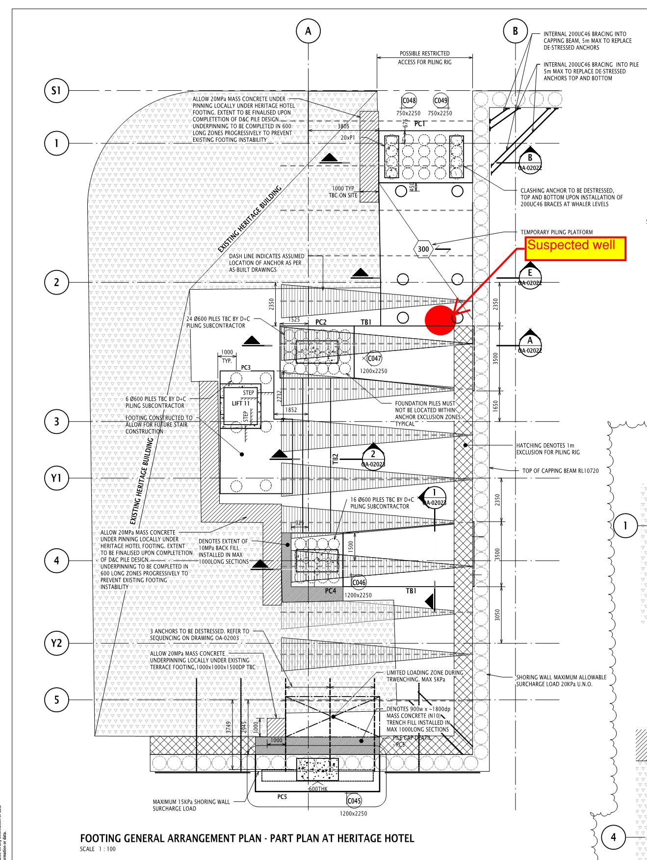
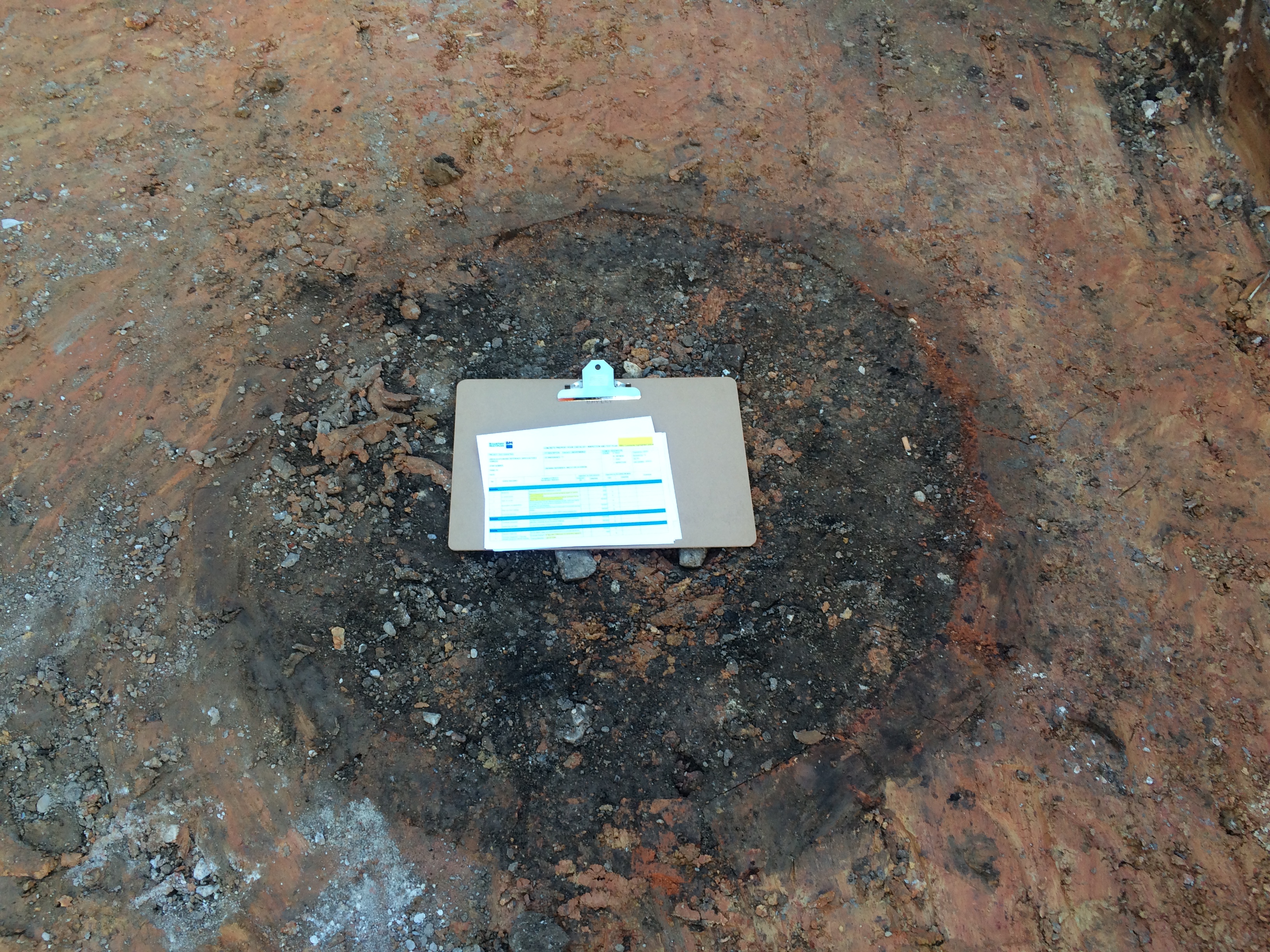
Figure 2 is an image of the well, after being ‘carefully discovered’ by an excavator. The well is approx 1.4m in diameter, the A3 clip board in the image gives an indication of the scale.
Figure 2.
Unfortunately, not only did the well caused me to cease works whilst the Archeologists investigate its historical importance, but it is located exactly where a tie back beam is designed to sit and almost exactly where a pile was designed to sit.
Fortunately the well issue has now been resolved. The Archeologists have conducted their assessment and have allowed us to continue and the clash with the beam and pile has been avoided. The well can be excavated to a reduced level sufficient enough to allow the tie back beam to bridge across it. The pile was required as part of a temporary piling bridge allowing us to use a 30t piling rig alongside the shoring wall. As a result of a separate issue, we have redesigned the foundation piles in this area, allowing a 20t rig to be used. The surcharge load resulting from the 20t rig can be resisted by the shoring wall without the assistance of a temporary piling bridge. The bridge and its piles are therefore no longer required – catastrophe avoided.
Project Update: A Relentless Pursuit for Cost, Quality and Time
Now TMR1 and Thesis Form A’s are out the way I thought I’d provide an update on placement progress and a few of the issues we have encountered along the way. As my title suggests many of these are occuring because of the relentless pressure on the construction team to deliver the project as quickly, cheaply and to uncompromisingly high quality . As we know from phase 1 something probably should be prioritised, unfortunately that doesn’t appear to be a well received strategy on site.
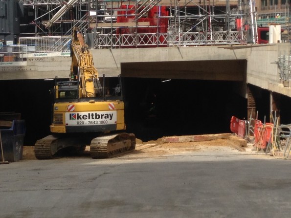
As you may recall (probably not) from my first blog we are using a top down methodology on the main Tower structure. Underneath the large Ground Floor (GF)slab we have unleashed the earth work contractors to crack on with the bulk excavation, taking our basement level from 9.0m OD to around 2.0m OD at its greatest point. This is a twelve week programme based on a target of moving 100 spoil vehicles away from site each day. The largest obstacle to this operation is not the digging or site movement of spoil, it is actually getting enough vehicles to and from site despite the constant challenge of breaking through London traffic. As such much of the earth is moved away at night which is probably proving a delight to our few local residents. To the sub-contractors credit they are doing well; they have their own exclusion zone so everyone else is able to keep out the way, which is useful considering the large number of excavators and dump trucks rattling around below our feet. Now they are underway tempo is impressively frenetic and as a result the ‘Bat Cave’ is taking shape nicely.
![IMG_0246[1]](https://pewpetblog.com/wp-content/uploads/2016/06/img_02461.jpg?w=595)
![IMG_0241[1]](https://pewpetblog.com/wp-content/uploads/2016/06/img_02411.jpg?w=595) The challenge of starting this process did throw up a nice on site leadership issue. After four weeks of hard work thrashing themselves to get the basement ready for commencement of this excavation , which they achieved, the junior construction team got a harsh email from a senior manager criticising quite a few trivial things on site. This inspired a near mutiny and, for a few days, a very inharmonious working environment. It was remedied by an honest, open conversation between various levels of management. One of the junior managers (not me I should add) fluctuated between near tears and incandescent rage when explaining his disapproval of the heavy criticism the on-site construction team was consistently receiving from, in his words, ‘Office bound desk jockeys’. Add a few favourite Aussie expletives in there behind the word jockey and you get the gist of his point. Everyone is now friends again, for the moment, but the unrelenting pressure applied by the project management team is starting to take its toll on morale. We shall see how long the current truce lasts.
The challenge of starting this process did throw up a nice on site leadership issue. After four weeks of hard work thrashing themselves to get the basement ready for commencement of this excavation , which they achieved, the junior construction team got a harsh email from a senior manager criticising quite a few trivial things on site. This inspired a near mutiny and, for a few days, a very inharmonious working environment. It was remedied by an honest, open conversation between various levels of management. One of the junior managers (not me I should add) fluctuated between near tears and incandescent rage when explaining his disapproval of the heavy criticism the on-site construction team was consistently receiving from, in his words, ‘Office bound desk jockeys’. Add a few favourite Aussie expletives in there behind the word jockey and you get the gist of his point. Everyone is now friends again, for the moment, but the unrelenting pressure applied by the project management team is starting to take its toll on morale. We shall see how long the current truce lasts.
Above the GF slab we have commenced structural steelwork on the main Tower, another key milestone. On Saturday six 20 Tonne steel columns were erected with a mobile crane. This was all going well until they realised that the lifting plates, temporary steel lifting connections attached to the head of each column, were fabricated in the wrong orientation. Fortunately, with use of a heavy duty steel drill and an extra few hours the issue got fixed and the columns were placed upright in the correct position. Drilling extra holes into precision fabricated steel elements on site isn’t an elegant solution but it worked. Now the columns are in place steel beams are starting to fly in (not literally of course) and the skeleton of the ground floor structure is rapidly taking shape. The steel erection is surprisingly quick and they are clearly a well-rehearsed team. Floor one will hopefully be complete in a few weeks, at which point we will have only 39 more storeys to go!


Above the steelwork the east slip form rig of the large central concrete core has begun to rise once again. Its currently at floor 8 and will pause at a pre-determined hold point on floor 10, allowing the western component of this core to catch up. We will not be able to progress the core beyond floor 10 until the pile cap is constructed in the basement. This controls the vertical load through the exposed plunge columns in the basement, primarily required to prevent them buckling which is obviously bad when you have 10 storey’s of reinforced concrete suspended on them. Once the pile cap is constructed the effective length of these columns is gradually reduced which allows us to increase the axial loads and continue the progress of the slip form.
We have also increased the Tower Cranes on site from 1 to 3. To make things more challenging we selected self-climbing cranes, one suspended inside each core. These effectively hang off the walls of the cores and climb up the lift shafts behind the slip form rig. Unfortunately this is reasonably new technology in the UK and nobody really understands the process for each climb or how long it will take. We really are making much of it up as we go along. What we do know is that if we don’t figure it out soon then the slip form rig will catch up with and hit the crane. This is problematic. The other excellent news is that our three cranes are all pretty much aligned on the same axis and therefore clash frequently. Trying to figure out which crane can do which task without impeding other works is like a giant Crystal Maze puzzle with no solution. This problem has an impressive number of intelligent people very confused for most hours of the day.

And in final news we had a very serious accident on site. A scaffold contractor fell roughly seven metres through a hole in the GF slab and into the basement excavation. I’m told that’s far enough to know you are falling before hitting the ground, which is obviously a long way. The investigation is ongoing so I can’t really add anything else other than that his injuries are, luckily, fairly minor considering the distance he fell. He landed on soft, loose soil which was very fortunate indeed. Had he hit the large item of plant located close by it probably would have been a different outcome. Without going into the details it looks like a freak accident, that said it proves the point that if something can go wrong, give it enough time and it probably will. Be careful out there folks!
In summary, tempo is relentless in order to maintain programme, quality cannot be compromised and the cost must be controlled. This all adds up to a very challenging construction project with lots at stake. More to follow once the excavation hits the pile cap OD.
Phase 3 Concluding Blog
My time on phase 3 is drawing to a close (3 weeks to go) and phase 2 have now been on site for a while and are possibly starting to consider their options for phase 3. I thought it might be worthwhile blogging about finding a phase 3 placement.
I’ve been attached at a company called Bryden Wood Limited. Bryden Wood is a small consultancy with approximately 80 employees split across four offices (London, St Albans, St Petersberg and Singapore).
How did I find my placement?
I used contacts I made whilst on phase 2. Carillion’s M&E design manager at Battersea had worked in consultancies previously and used his contacts to get me an interview / informal chat at BWL. That chat was pretty pain free and was as much about me confirming that BWL could for fill my requirements. Other options that were open to me but that I didn’t follow up were working for Carillion’s consultants. I didn’t pursue that option as I felt there would be too much risk of being sucked into working on design associated with Battersea.
Advantages of working at Bryden Wood:
The advantage of working for a small company like Bryden Wood is that I don’t feel like a small cog in a huge unwieldly beast (which was often the case at Battersea). The projects I’ve been involved in have been relatively small in size, which means I’ve had a great deal of autonomy on them, which has been very useful for gaining experience. The company also doesn’t feel particularly corporate and has a family feel to it, which makes it a nice environment to work in.
Downside / Risk of working at Bryden Wood:
The main downside of working for a small company like Bryden Wood is that there is a bit more risk in terms of the amount of work available. We’ve had a few projects put on hold, which has led to contractors and permanent staff being laid off. This has led to the number of projects I could get involved with being reduced, that being said I’ve never been without work; although for my last two weeks it looks like I’ll be doing some pretty mundane CAD work.
Potential Opportunities
In summary I think my attachment at BWL has worked well. Although I’ve not covered as many projects as I thought I would do at the start of phase 3 I think I’ve covered enough – the proof will come in a few weeks at CPR. I still stand by my decision to go for a smallish firm. I’d recommend BWL to any M&Es looking for a placement in London or Hertfordshire. I’d be more than happy to make introductions if anyone wanted look at them for a possible phase 3 attachment.
I want problems not solutions!
Not much to report on my site due to construction delays resulting in no on-site E&M activity and so my days are currently spent reviewing tender bids and checking designs. So instead of blogging about something interesting happening on site I thought I would write about a little ‘wrist slap’ I got the other day which for me highlighted a key difference of how we as Army Officers sometimes ‘do business’ compared to Engineers and Project Managers in industry. I hope this may serve as a warning to others or the Phase 1s.
Last week I was reviewing the mountings for three 11T chillers and calculated that they had a uniformly distributed load of 14kN/m^2 which exceeds the slabs design load of 9kN/m^2. Also these chillers are mounted in the centre of the slab and exert a maximum point load of 31kN which again exceeds the specified design loads.
Since we are under a management-only contact, the responsibility for the design of steelwork mounts or slab reinforcement lies firmly with the Principle Designers, in this case BDP. So I wrote an email to BDP explaining the problem and in good Army Officer fashion, I didn’t just point out an issue but also suggested 3 possible solutions that we in the office had been discussing based on the specification of the selected chillers which up to now the designer had no visibility of. So, a job well done thinks I and I move onto another task until the designer replies with a developed course of action.
Anyway, within a few hours I received an email back from a member of the project working for Skanska instructing me to not ‘suggest’ potential solutions in future correspondence to the designers. This is because the designer (who is getting a reputation for cutting corners and doing as little work as is possible within the confines of the contract) will likely read the email and just choose one of my suggested solutions without investigating it further or developing a detailed design as I had hoped. Furthermore the designer would likely list Skanska as being responsible for this design change which would ultimately result in Skanska unknowingly accepting a significant design risk. Oopps!
So from this I have learnt that although some of the methods we have developed in the Military are generally very useful and well received in industry, we still need to be careful as they may not always be the most appropriate and we cannot always assume that those around us will also act in a similar ‘good ole military fashion’.
Who turned off the power?
Situation
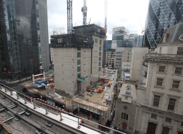
Laing O’Rourke (LOR) originally constructed the original substructure (75% of the 3 floor Basements) and installed the Temporary Building Supply (TBS) consisting of an enclosure and network substation. It was positioned in an area that would not conflict with the original substructure works but it would need to be moved before LOR returned to site to complete the substructure.

Reflection
Brookfield inherited the site from LOR and have been entirely focused on the construction of the tower. In the process they have neglected to carry out sufficient analysis regarding the temporary power and realising the potential impact. The TBS and RMU should have been moved earlier in the programme or the temporary power layout should have considered the future move.
Instead the project has progressed and increased the impact of the pending change by having more steel wire armoured (SWA) cables installed directly from the Ring Main Unit (RMU) to the large plant, cranes and hoists, wet riser system and welfare facilities.
Issue
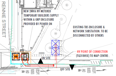
Power On (HV specialist) and UK Power Networks (District Network Operator) were required to do the majority of the works to install the new TBS (1x 2MVA transformer). In order to switch the HV connection from the old TBS all the power to the site needed to be isolated.
Mitigation
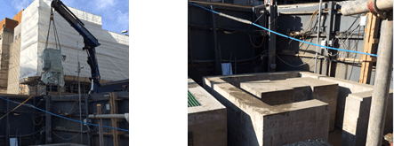
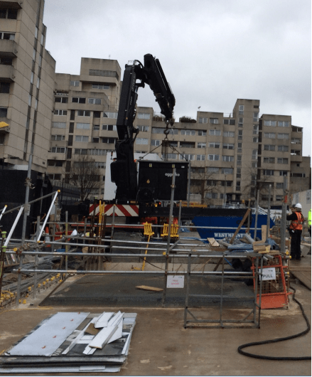
In order to reduce the impact of the power outage the option of hiring 2x 500kVA generators was taken. The problem of siting 2x generators on a construction site was finding 6m2 of flat ground with enough strength from the concrete slab. The area North of the new TBS was identified, Aggreko (generator sub-contractor) visited the site, agreed to install the generators with extra fuel capacity by conducting the lift from Rennie Street.
When Aggreko delivered the generators, the Crane Op was unable to place the generators from Rennie Street. Therefore the decision was taken to conduct the lift from the pit lane and site one generator. It caused problems for the deliveries on that day but ultimately prevented a larger problem from unfolding.
Environmental
This was raised and checked by the Environmental specialist on site:-
From 1st September 2015 construction projects within the Greater London Area are required comply with the London Low Emission Zone Non-Road Mobile Machinery (NRMM) requirements. All NRMM with an engine net power between 37kW and 560kW must meet minimum standards in terms of exhaust of Nitrogen Oxides and Particulate Matter. All qualifying plant must be recorded in an online register and those that do not meet the require standard have to be replaced.
Anyone else experienced any emissions restrictions?
Oz PCH – Subbies not getting paid…never!
I saw this in this week’s The Western Australian and thought it worth a share…
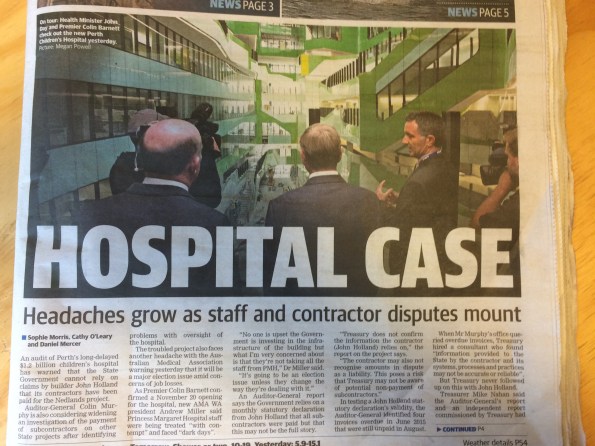

If the print is too small to read is summaries that JHG are submitting false statutory payment declarations to the State Government of WA (the client). This particular subbie is owed $335k for works completed and there are others who also claim they are owed for work but are reluctant to speak out while they hope their disputes can still be resolved.
There is also talk about the façade subbie, Yuanda who are reported to be owed $12 million. However, this is due to a dispute over a number of faulty/damaged panels. I think JHG are worried that the cost involved of replacing so many panels is not worth what Yuanda would stem to lose and so fear they would just walk away and not bother – hence JHG withholding payment – which we all know, to use Australian slang, is just not cricket.
The devil will be in the detail and the report goes on to say that the Auditor-General’s review found JHG had presented “reasonable” grounds why amounts claimed by subcontractors had not been paid.
Raystown Dam & Reservoir
Raystown
I was toying with a semi-technical blog, but then realised I hadn’t actually finished my “interesting things that USACE do that the Royal Engineers don’t do” mini-series. So here goes, today I’ll be looking at the Raystown dam and reservoir.
I visited the site a couple of weeks ago. This gave me the opportunity to tour the facilities, but seeing as it’s located 175 miles from Baltimore in the middle of deepest darkest Pennsylvania it also afforded a good excuse to do some walking and go camping for a night. It was also the piece of critical national infrastructure that the cadets had to go and ‘recon’ so it made sense to do backbriefs etc on-location.
Anyway, a bit of background: Construction began in 1968, and it was by most accounts quite unpopular at the time; the perceived wisdom being that all available funds should be used to support troops in Vietnam! Construction was completed in 1972, and the accompanying recreation area was inaugurated a couple of years later in 1974. The principal purpose of the dam was flood defence, with the creation of a recreation area a close second. Power generation wasn’t even considered at this stage, however a 21MW hydroelectric plant has subsequently been added. Interestingly this is the only part of the site (including wildlife management schemes) that isn’t directly administered by USACE. Immediately following construction, the area was hit by tropical storm Agnes, which all but filled the reservoir only months after completion. Had the dam not been built the Juniata (and subsequent valleys) would have experienced the worst flooding on record.

Raystown Earth Dam
Some facts and figures then: The principal dam is 69m high, with a planned ‘constant’ water depth of 58m at the deepest point by the dam. The dam itself is a classic earth (or embankment) dam with a clay core. Material for the dam was harvested nearby, in an area which now serves as the emergency spillway should the reservoir overfill and other mitigation measures fail. There is a secondary (much smaller) concrete dam which houses the main spillways and regulation gates. The hydroelectric plant has its own water feed and under normal operation all water leaving the reservoir passes through the plant. The spillway is only utilised when the volume of water in the reservoir becomes too great for the plant to handle on its own. The lake is approximately 45km long, has a 180km long shoreline, covers an area of 34km2, and has a flood capacity of around 306,000,000m3. Interestingly there is no ‘Raystown’ nearby. I asked about this, and the only answer I could get is that the project was named after a local trapper (presumably called Ray) of some fame from “the old days”!

Concrete Dam and Spillway
Some interesting engineering points came out of the facilities tour. During construction 5 massive movable steel bulkheads were created and ingeniously stored within the dam. The idea being that when required they could be hoisted out and dropped into position across the spillways allowing the main gates to be serviced. However, once lowered into position the designers failed to take into account the ergonomics of the finished dam. When it came to using them for the first time it became apparent that no crane could get close enough to lift them out because they are unable to deploy their spreaders sufficiently on the service road on the top of the dam. The bulkheads have thus sat undisturbed, entombed in the dam since 1971! Down at the bottom of the dam (below the lowest water level) there are a series of walls drains to reduce the pore-water pressures acting against the foot of the dam. There are also a series of “bubblers” which are simple air pipes used to pump air out from the bottom of the spillway entrance in order to circulate water and to try and prevent or reduce damage caused by water freezing in and around the spillway gates. There are three separate water inlets from three different depths within the reservoir. This allows the operator to take different proportions of water from different depths in order to mix them and achieve the desired temperature before releasing water downstream; an important environmental consideration.


Emergency Spillway Tower & Bubblers and Wall-drains (within the concrete dam)
The reservoir also has a ‘plughole’, or in this case a 9m x 6m tunnel which runs from the bottom of the original valley out into the river beyond the dam. It has never had to be utilised, but it is controlled from a giant tower which stands in the middle of the emergency spillway. During the tour we were able to go down and look at the giant pistons which operate the ‘plug’. Also of engineering interest is the emergency spillway. This appear to be just a giant field, however it has been engineered to have specific properties. The upper lip is bedrock which has been chiselled out of the hill in order to form a specific level below which the water will remain contained in the lake. Onto this however an earth bund has been installed which is approximately 1m high. This is made is made of ‘erodeable’ material which has been designed so that it will contain water up to a certain height, but that once breached it will be washed away emptying the lake down to the level of the bedrock lip. Simple but clever engineering.
During my visit, I had to keep reminding myself that the site was completely designed, built and managed by USACE, and that this represents one of many similar projects across the country. The reach and scope of the organisation is quite staggering, it really is a very different beast to our own military.
Other News
It looks like some of the QC contractors will be losing their jobs soon. Apparently it’s not okay to just turn up at meetings, make promises then not do anything. They have two weeks to turn it all around but it’s not looking good! More to follow. Finally, bacon covered doughnut anyone?………….

What do you do when you pour the wrong concrete?
Well, apparently nothing. A recent issue we have had at the NLE involves a situation where we “accidentally” poured the wrong concrete. Of course there were processes in place that should have prevented this but it still happened.
The pour in question was for a 2m x 2m section of capping beam 8m long. The design requires a C50/60 concrete strength (C50/60 20mm CIIIA+SR DC-3). Unfortunately the last 13m3 poured was a C32/40 20mm CIIIIA WRA Pump Mix (a Temporary Works concrete mix). Not great for the 150 year life span required by the client.
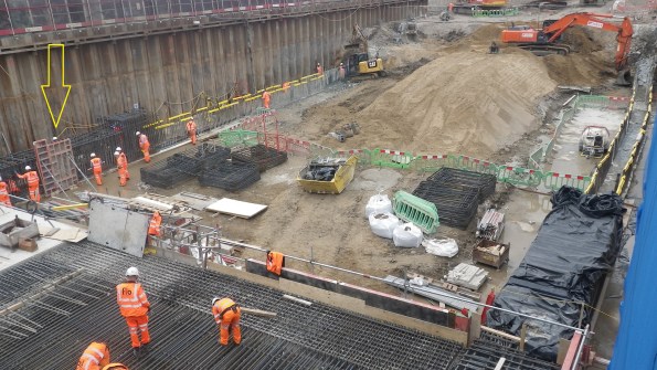
Pour 5 – South side of Capping Beam (yellow arrow)
This particular section started pouring at 1715 (a slab was also poured earlier in the day). And whilst the concrete was only just going warm and the pump was still being cleaned out the site engineer at 8pm then realised the issue. The fact that almost the entire workforce had already left the immediate call was to leave it in. The next morning, once we understood the full picture, again the decision was made to leave it in. Of course if you are going to strip it out you want to do that as soon as possible before the concrete gains any significant strength. So what was the perfect storm that led to this problem happening in the first place?
Supply
The concrete is being supplied by London Concrete, and although only one mix was ordered that day the supplier changed the mix after 8 loads (62m3) for the last 2 loads (13m3). London Concretes reason for this is that a computer crash required the staff to re-input the mix design which they got wrong. Crucially the delivery ticket did show C32/40 mix.
Checking
The site if using a sub-contractor (ESG) to conduct testing of concrete. Flow tests are taken on every load and cubes every 50m3. Incidentally they are meant to also check the mix design. The C50/60 concrete is designed to have a 600mm flow where as the C32/40 concrete is a much stiffer mix and designed to have a 170mm slump. When tested the C32/40 mix achieved 560mm flow! – so the load passed and was accepted. Quite luckily 4 cubes were taken for this load.
Pre-pour checks
Finally the site engineers are meant to check the delivery tickets, test and accept the load. Whilst they do this they fill out a pre-pour inspection sheet. Unfortunately the practice that has crept in is that the Site Engineers collect the tickets and fill out the inspection sheet later after the pour in the office. Incidentally no one noticed the difference in mix when it was loaded into the pump or when it was placed.


Resolution
Well, once the decision was made not to strip it out early you might as well leave it and see how it goes. 7 day cubes achieved 35kN/m2 so we are pretty confident that the final strength will achieve at least 40kN/m2.
Removal – If we were to remove the offending concrete (about 0.65m from the top) we would need to hydro-dem it off. High pressure water jet that strips concrete (queue much YouTube video research on what this entailed). This is apparently very cool and efficient but expensive and requires a lot of measures to protect people from flying concrete. The estimated cost came in at £200,000 to go down this avenue (not including the cost of additional concrete which would have been negligible in comparison). As the project Manager said “I would rather have to paint the beam in gold than have to strip it out”.
Re-analysis – The principle designers were good and very quick at giving their assessment within hours of being told the next morning. Their assessment is that a reduction in concrete strength reduces the bending capacity, bond strength and shear capacity. The bond strength is the most significant. However in another stroke of luck we changed the top and bottom laps to couplers to assist the construction programme which laps only in the side reinforcement. A review of the beam calculated as if it was all C32/40 and it showed that the section had adequate capacity.
The only concern Motts has is over the durability, the C32/40 design mix complies with DC-2 chemical class where as DC-1 is required. This means that we need to ensure that our backfill material is tested for sulphate content – this is an easy fix.(having had a look though Eurocode 2, I can’t see any reference to DC chemical classes. I will ask next time I see Motts but does anyone know where this reference comes from?)
Outcome
London underground have now officially received this information during a joint client/contractor/designer meeting yesterday and they are reviewing. Hopefully they should accept it but they are within their rights to ask for it to be replaced. This is a target price contract (50:50) but being a defect the cost would fall all on FLO.
In chatting with the structural engineering team they say that the reduction on concrete grade has little effect on the section capacity. I am not sure on the loads but I certainly remember quite a high sensitivity of concrete strength on the capacity of a section. Which implies that there is plenty of “fat” in the design. Additionally the impact I have noticed with the operatives is the impression that mistakes like this are ok to make which really is the wrong message. We have amended the processes on site. It was a close call which we just got away with. Had circumstances been slightly differently, we might be coating the beam in gold!
