Archive
The customer is always right. Or are they?
A quick bit of background: The St George Hospital construction project is funded by Health Infrastructure (part of the Ministry of Health), the end users are from the Local Health District (New South Wales Health). Brookfield Multiplex are the principal contractor and the contract is with HI; there is no formal agreement between BMPX and the local health board. However, whilst HI allow the non-financial decisions to be made by the end users they are not formally a decision until HI have confirmed them. As the CI pointed out during his visit, this is very similar to the set up of DIO/MoD (read HI/MoH) and the Army/Navy/RAF (read end users).
The issue: In the first two months with BMPX I have spent an inordinate amount of time in user groups, workshops and completing reviews of marked-up documents. It seems like every time we have a review the number of comments and changes increase rather than decrease. Therefore, at what point do you stop asking the client what they want and simply tell them what they are getting?
Taking Security as an example; during the concept design phase the security drawings were signed off by the LHD management, the variation costs agreed with HI and the documents updated by the subcontractor. Subsequently there was a review of which doors needed to be automatic and which needed to be held open. Again, these were agreed with the LHD management, the variation agreed with HI, and the drawings updated by the subbie. At this point the drawings landed on my desk with the instruction of “can you set up a final review to close out the final comments on these”. Simple. The result of this “final review” was nearly 12 hours of user groups spread over 3 weeks and over 150 new comments, questions, alterations and good ideas from the nurses and doctors that will use the new hospital. All this has to go back to LHD management and the financiers at HI to review and accept/reject. Only then can the drawings be updated (again) and a “final, final” review be conducted – I may forget to invite anyone else to this and just issue the drawings.
Luckily for me, as I did such a good job with the security workshops I now get to do the Medical Service Panels and the Nurse Call as well. Over the next few weeks if you see the headline “Army Officer beats up nurses with rolled up design drawings” you will know why!
The solution: ?
Wood Street Police Station
At the risk of sounding like Jessy from the fast show (for those old enough to remember that): This week I have been mostly working on the redevelopment of the Wood Street Police station…
This is the headquarters of the City of London Police (CoLP). A sub-branch of the Met that look after the area around St Pauls and the financial district in the centre of London. The site was built between 1963-66 and sits within a compound containing buildings sat around a central courtyard, all on a two storey basement.


I can’t give you plans or internal pictures of this as I’m not allowed to download them from our secure server. Apparently they think me not trust worthy. What do they think I’m going to do? Upload them to a blog? How dare they?! SO all these photos are open source. And if you really a look inside you can watch this: http://www.bbc.co.uk/iplayer/episode/p01rrjbx/building-sights-series-4-5-wood-street-police-station
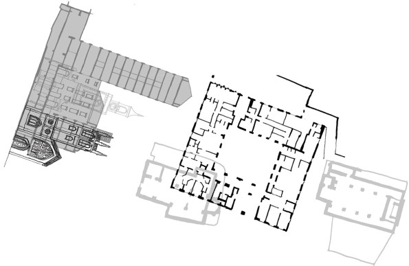
The plan is to put a 16 story tower in that courtyard adjacent to the existing tower. There are some problems with this…
Firstly the foundation design. The site is probably sat on London clay. I say probably because the CoLP won’t allow any sort of site investigation until planning has been granted since it would require a hole in the raft slab, and they don’t want one! It might have a couple of meters of gravel, but right now we don’t know. We also don’t know the ground water regime. We can guess it, and the best guess is that as soon as you cut through the raft slab water will come out. So currently the plan is to inject resin into the granular fill in order to drain the water within the working area. Gravel or not it will need piling, which leads to…
Access. The courtyard is entirely enclosed and access is via one of two vehicle “doors”. One leads into the courtyard itself and is both wide enough for a Range Rover type vehicle and tall enough for a dude on a horse. The problem with that door is that the slab that it leads onto will be removed in order to build the new building. So that doesn’t help. Behind door number two is the ramp that leads down into the basement. In order to get down to the second basement level you have to drive through the first level (that slab is coming out too) and down another ramp. You can get a low clearance piling rig, so you could drive one down. But it would be mega tricky. The better option looks like it’ll be to remove the slabs, ramps and all, and crane in the rig. There is the question of how you get the broken out slabs out. It’ll probably involve a skip, a crane and loads of pissed off people trying to get around the truck parked in the road…
There are other problems too. In order to properly assess the existing structures we went into the basement with a rebar meter. The results were a little confusing. Then we found some photos of the construction of the building and it looks like the members are steel, then encased in concrete for fire protection. Some of the transfer beams are about 2 meters deep, so breaking those out will be fun! We couldn’t get any more information as we’re not allowed to do any destructive testing until the budget has been confirmed. The budget can’t be confirmed until the planning pack has been submitted. In order to submit the planning pack we need to know what we’re doing. Which we don’t because we’re not allowed to drill a hole in the floor and find out what’s below it (among other reasons)… It’s the classic circular reference (to use an excel terminology – one for Damo).
All of this makes planning the cost of the project extremely difficult. For whatever reason WYG seem to be the only people running for this job. Maybe because it’s such a nightmare. But the in-house PM and blast analysis combination is definitely a bonus for CoLP since the new building will have to be designed to withstand an attack. That and planning this whole thing is a nightmare!
So while the structures team in Nottingham are wanting to get stuck into some Bentley action, they can’t, because if they do they might not get paid. First we have to work out what can be done, and how…
Oz NDY – IMechE CEng CPR Application Issues – Forewarned is Forearmed

This blog highlights some issues experienced of the IMechE CEng Chartered Professional Review Application process and previous academic review documentation. It also discusses hints and tips on CPR submission.
The main issue seems to stem back to the initial academic review submission that is required if your first degree is not accredited by the IMechE. I submitted my academic review back in 2012, at which time I wasn’t really clued-up on the whole chartership process. It is possible other E&M students on Ph2 might have had to do the same and could unknowingly be in a similar situation I found myself in. If so or unsure, now is the time to check and avoid it being a surprise and slight embuggerance if something needs to be submitted short notice.
The Issue
When you submit you CEng CPR application, more on that below, someone from the membership team will review it alongside your previously submitted academic review. One question on your academic review asks what level of registration you want to be assessed against. Make sure you have ticked the box for either CEng or Both. I ticked IEng only, thinking I would be awarded IEng form that point onward not realising that I would also need to submit CPR evidence and sit an interview at that stage. This was something I wasn’t planning on, thinking that I’d just wait until I had completed the MSc and simply submit CEng CPR evidence then (as I have done).
This sparked the notification that the IMechE can’t assess you for CEng if you haven’t ticked that CEng box (or Both) on the academic review. I’m still not entirely sure why, especially after explaining that nothing has changed from the initial academic review (which has IEng ticked) to the latest one I have had to submit (which has CEng ticked). Just seems like a whole lot of wasted time and effort due to a tick in the wrong box, but the process is the process and clearly some other internal shenanigans that can’t be messed with.
As for the CEng CPR application this is relatively straight forward but there are a few hints and tips I’d like to share to make it that bit smoother for when others come to do it:
- The IMechE website isn’t the most intuitive to navigate so use the link below to the application process.https://www.imeche.org/membership-registration/become-a-member/chartered-engineer/application-guidance
- Download the PDF doc and fill that in with the ability to easily edit and see what it looks like in the form.
- Download the exemplar as a guide or ask one of my cohort for a copy of theirs.
- Irrespective if you have used the PDF form or not you will still need to complete and submit the on-line form as this is linked to the application payment method. Once complete you can download a PDF of that on-line submission.
- I found it best to initially write in a word doc then copy and paste across – that way you can ensure you are within the word count, which although they say ‘approximately/around 400 words’ for each competence, they actually mean ‘no more than’ as some sections won’t let you progress if over the limit.
- The PDF form asks for signatures of your two sponsors yet the on-line form just asks you to confirm (via tick of a box) that they have read a copy of your application before you actually send it – so no need to actually get the PDF copy signed. IMechE send an email out to your sponsors anyway with a ‘no action’ verification statement.
- The on-line form initially asks you to complete your personal details prior to the competences sections. This is easiest entered prior to completing the form by going through the My Profile in Your Account. Of particular note is ensuring you enter phone numbers under the Personal and Work tabs, even though the work tab phone numbers are not *stared. I just added SI PET’s for the direct dial landline – but I’d like to think they’d call you on your personal phone first. Without these numbers entered the form seems to stop you continuing to the next section when completing on-line.
- There may be some other glitches I haven’t come across so anyone else who’s submitted forms feel free to comment.
How stuff works: post tensioning.
As I was walking around site in the beautiful sunshine of Sydney’s first day of “winter” I found myself staring at the PT cables in a new slab and wondering how it actually works. Whilst I fully understand the theory of post tensioning, I was unsure why the cables were is conduit – so my question is: if the the cables are not in contact with the concrete, how do they transfer the tension into the slab?
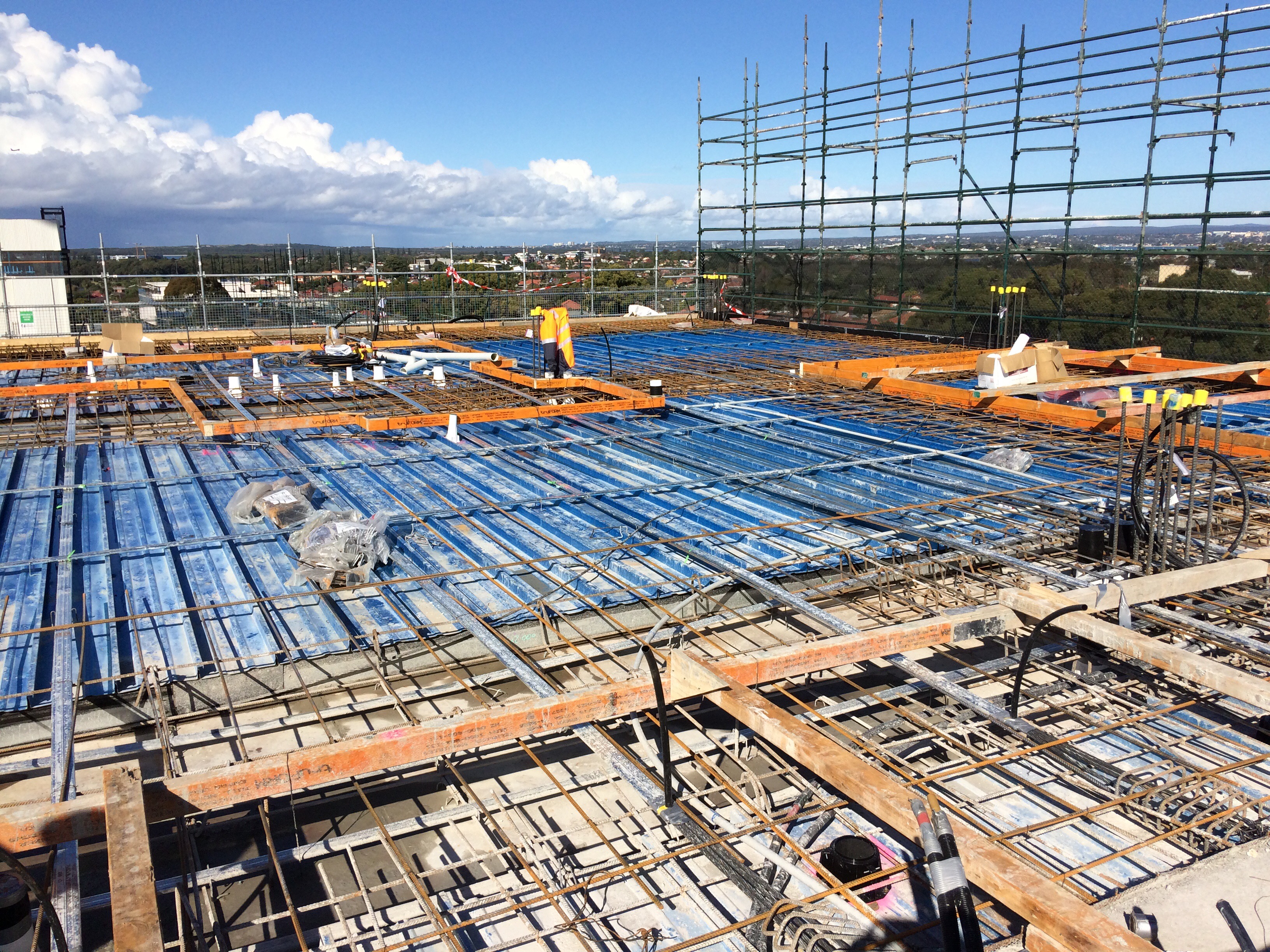
PT cables in conduits
Answers on a post card please.
Beer Economy
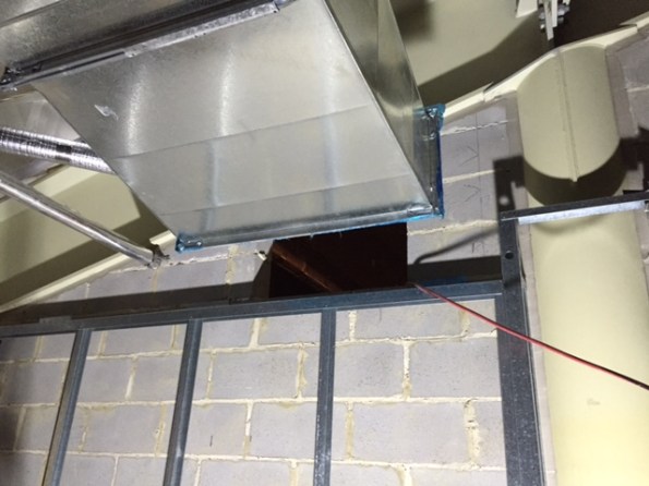
Has anyone else experienced the ‘beer economy’? Credit for anyone who knows the going rate for removing the three and a half blocks detailed in the picture below. It would personally take me 4 minutes with a Stihl Saw.
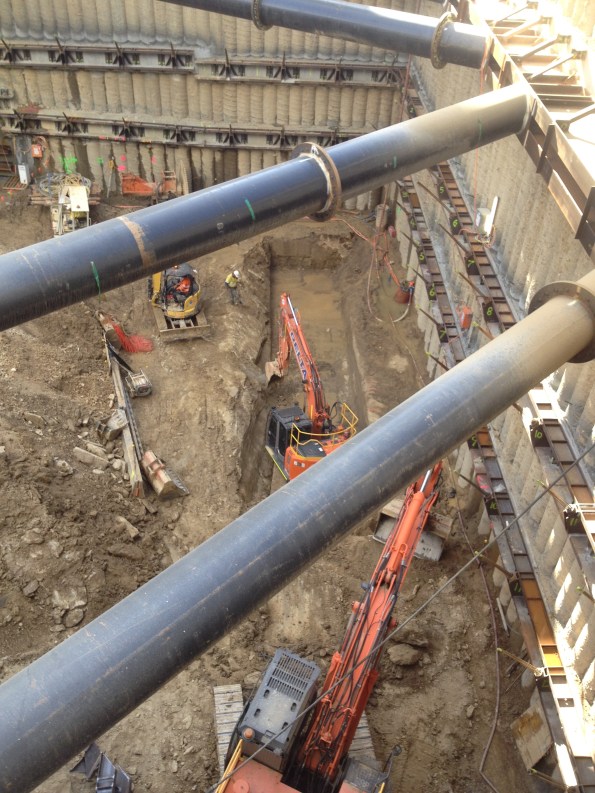
Bored piles – analysis of issues and recommendations
As promised in a previous blog, see below for a synopsis of the key risks, issues and recommendations from the piling on Australia 108
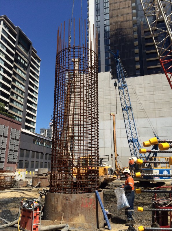
Analysis of issues encountered with bored piles
The delivery of deep foundations on any large project is always on the critical path. The risks inherent to piling are substantial and failure to identify and mitigate these risks adequately can lead to significant impact on cost, schedule and performance of the piles. Both the client and contractor have a vested interest to develop and implement an effective risk mitigation strategy to avoid such risks from being realised. The recurring nature of some of the key issues during piling on Australia 108 signifies they did not occur by misfortune indicating that risk could have been managed better, and some issues avoided.
There are two primary requirements associated with piles: piled foundations must have both the structural capacity and geotechnical bearing capacity to safely transfer the actions from the superstructure to the ground without requiring excessive strain to develop the load capacity.
Risk and mitigation
Risks associated with piling are generally accepted as fitting four categories:
- Risk of encountering unexpected ground conditions.
- Risk to foundation performance.
- Risk to construction productivity.
- Risk of construction defects.
Mitigation strategies generally adopted:
- Geotechnical Design Report. Identification of risk and recommended design solution. Any residual risk should be identified to ensure it can be mitigated through construction processes.
- Risk Transfer. Design-Construct contracts transfers some risk to the subcontractor. Costs can always be passed to the subcontractor if they fail to mitigate risk appropriately, however time cannot be recouped once lost due to delay. The attempt to reduce the overall project delay applies early pressure to a program which will often risk compromising quality.
- Testing pile performance. This verifies that piles have reached their design performance criteria. Increasing the rate and reliability of testing procedures affords greater design resistance to the piles, increasing the redundancy they offer for the same design effect.
- Construction methodology. This must be simple and specific to mitigate residual risk from design by avoiding any ambiguity or interpretation in construction procedures.
- Technical competence. The most effective way to mitigate risk is being able to recognise early that a risk is materialising as an issue. A timely, informed decision on appropriate action to mitigate that risk, balancing time and cost, is essential to limit the impact of that risk.
The underlying causes of materialised risk are often:
- Failure to identify the risk.
- Failure to recognise the risk was becoming an issues.
- The risk was identified but inappropriately evaluated.
- The was identified but due to either time or cost incentives, risk mitigation was not applied.
Australia 108
Foreseeable risks on Australia 108
- Difficulty drilling through the basalt in the Northern sector.
- Settlement of Coode Island Silt (clay) relative to the piles creating negative skin friction.
- Necking of the boreholes due to the soft clay collapsing and loss/contamination of polymer support fluid with ground water through gravel layers.
- Ability to core for establishment of pile in siltstone.
- Structural capacity of the pile due to high axial loads and eccentricities.
Issues encountered on Australia 108
- Out of position piles. 35% of 48 bored piles were out of position by more than the tolerance leading to significant rectification measures and redesign.
- Reduced drilling rates through basalt. The basalt encountered was harder and thicker than anticipated significantly slowing progress.
- Voided pile. The voided pile was due to broken equipment abandoned in the borehole while drilling through basalt. This resulted in additional piles being drilled either side and significantly increasing ground works to gain access.
- Borehole collapse. Either identified during drilling which required additional drilling to correct; or during the concrete pour which risked the performance of the piles and additional testing was required to verify the pile.
- Excessive sediments. Encountered in the base of piles and required significant airlifting prior to pouring, sometimes resulting in concrete pour being delayed a day due to the remaining time on site being insufficient to pour.
- Pile cages placed too low. Cages installed at incorrect RLs required additional breaking back of piles in 80MPa concrete to locate cage followed by rectification of pile and additional welded bar to ensure correct development length of starter bars.
Recommendations
- Identify the high risk piles using probability vs impact of risk materialising. This will focus QA efforts on the right piles.
- Be specific in the construction methodology about techniques to be used to reduce any ambiguity. Ensure it is followed on site. Measures in the construction methodology are there to mitigate risk.
- Check location of casing of bored piles after drilling before pouring. Out of tolerance piles can be evaluated prior to pouring. Redrilling of the pile now may have less impact on the program than rectification measures to the structure later. (This might be implemented for the piles identified as high risk).
- Use of GPS in the drilling rig will give real-time information on location, depth and verticality of the borehole allowing early identification of casing shift.
- Appropriate identification and classification of soils strata, specifically rock with regard to location and strength. On Australia 108, the basalt was not included in the design stratigraphy for the piles.
- If using polymer, slow and steady extraction rates of the drill reduces the likelihood of suction on the boreholes, reducing the effectiveness of the polymer chains used to support the borehole. If collapse is occurring in soft soils, slow the drilling and extraction rate down.
- Keep polymer levels 1-2m above the ground water level to reduce the risk of borehole collapse.
- Good polymer management is key to reducing the sediment within the polymer; especially prevalent when recycling the polymer from one borehole to another. Reducing the sediment pumped into the boreholes, reduces the need to pump out prior to pouring.
- Good polymer management is key to ensuring the polymer chains are effective. Check the length of the polymer chains dripping from the drill on extraction. Long chains indicate an effective polymer. Shorter chains indicate that new polymer needs to be mixed in.
- Requirement to check the RL of the pile cage prior to pouring. If necessary, the pile cages can be built up above the level of the polymer to check; or the length and laps of the cages be checked and recorded prior to installation.
Vertically Challenged
My scope of works in delivering the detailed design of two overtaking lanes (OTLs) in the middle of nowhere included identifying any show stoppers during a site walkover survey, which I did – twice.
Now that the design is well and truly underway, we have found that the vertical alignment does not meet the Austroads sight safety distances. So what? Well the Client stated the OTLs are to tie into the existing pavement which implies the vertical alignment is okay. Should I have identified this show-stopper? Impossible without a $20k survey.
What now? I rang the Client and told them what we had discovered. But they pay us for solutions, not problems. Understandably, they weren’t too chuffed with my solutions:
- Reduce the speed limit on the OTL to 80km/h. Yup. Genuine option.
- Regrade the zones to meet the safety standards. $$$$.
How could this happen? Well, the highway was built decades before the standards were published. Effectively, most of the highways in AUS could be sub-standard.
In my opinion, the Client is going to have to re-grade, or just accept the risk that someone might not see a 20cm high bunny rabbit from 210m away and just run it over. Easter is over-rated anyway.

We will rock you
So in my last post I said I would cover a little about working with rock. I am currently excavating in low to medium strength phyllite. Phyllite is a metamorphic mudstone somewhere between slate and schist. It is highly foliated and has fine clay like material in between the layers. The foliation is at 70 degrees to the horizontal across the site. Despite being fairly weathered it is still relatively intact with only a few faults across the site. RQD was between 50-75 % across site. The problem is it weathers so incredibly quickly when wet. I am about 15 m below the water table and water coming through the anchors at about 5 litres per minute. So what I hear you cry – well its rock but it is a galactic pain in the back side to work with.
I am now down at footing level and I am faced with an even worse problem than the bulk excavation. The design has called for individual pad footings which are all at different levels and a core that is 3 m below any of the other pad footings. There are zone of influence clashes everywhere, the architect/structural engineers have very helpfully not included any footing RL so I have had to work them out, as well as how we are going to get the batters and benches in while still being able to move. The geotechnical report states that with low strength phyillite I can achieve a batter of 0.7 H and meduim strength 0.5 H. With H being the height of the batter (not exceeding 3m). So rock strength can be pretty important.Footings Handover Schedule
What strength is that rock? You cannot just take the results of the lab test for Ultimate compressive strength and point load tests. There is a very good website that helps with estimating rock strength via the Rock Mass Rating (RMR) process (RMR rating)that can be then used to calculate the allowable/safe bearing pressure for foundation design. Ultimately though this counts for very little as to get anything signed off you end up with a geotech going mental with a geo hammer on site before telling you its half of the strength you have calculated.
A conversation with the local geotech went along the lines of “how do you come up with the safe bearing pressure do you use RMR.”
“RMR what’s that? Nah, I just use experience, umm what does the drawings say this should be?”
Incidentally I got an RMR of around 45 -50 across the site. That gives between 2880- 1510 KPa am I right?

I made the mistake of being over confident with the bench and ended up having get the geotech back in. In my defence I excavated a pad footing expecting it to be open for the maximum of a week and the PM didn’t make the call on the steel contractors in time so it was open for nearly 3 weeks. The result was water got in and the sides blew out, I had to get the geotech and subbies back in to batter back a ridiculous amount. This all meant time, concrete and money.
There is worse to come – the other Site engineer (little e deliberate)- to be now known as ‘the lone ranger’ took responsibility for the crane base and has massively ‘dropped his baseball’. He wrongly measured the zone of influence of the crane base to the core and failed to gain approval for the design of the pad footing from the geotechs. We are now faced with delaying the tower crane erection or digging the pad footing deeper. It hopefully won’t end up like the crane around the corner though, which has a lovely lean to it. 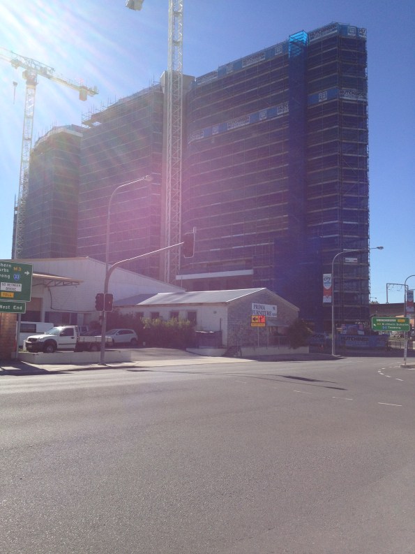
Prima furniture may be getting some renovation work done in the future.
Calling all aspiring structural engineers
Evening all,
A short and sweet post. As a lowly E&M engineer in training I am interested in some second opinions on the deflection of steel structures under load.
This week I have been occupied with installing temporary tunnel ventilation fans in the -5 level of Bond Street Station. The fans weigh around 3500kgs and will be in operation for around 18 months. The first of four fans was due to be moved into place today using a porta-gantry onto a simple steel frame.
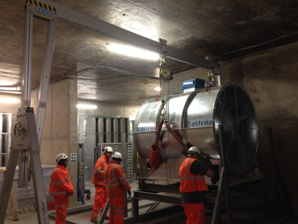
The fan being lowered into position on the support frame
Upon lowering the fan onto the support one of the operatives spotted a part of the frame deflecting under the applied load. The web of a channel section was bending inwards as the chain hoist lowered the fan, distorting the anti-vibration mounts.
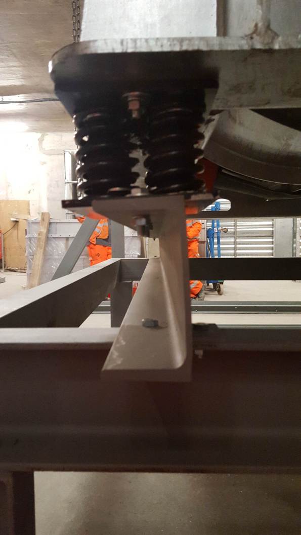
Apologies for the poor photo. If you draw a line along the top and bottom flanges of the C-section they are no longer parallel; causing distortion to the anti-vibration mounts. The lift was stopped before the full load was applied.
This would all be highly interesting except for the fact that I am only SMSTS qualified person on site and conducted the brief for the works. It also came down to me and a grad mechanical engineer to judge whether the deflection the channel was showing was acceptable, and whether to continue lowering the full load onto the deflecting frame. After some teeth sucking and discussion with the lift AP we decided to lift it back off and question the frame designers. Queue a lot of Northern blokes pissed off that they had wasted a days’ work. Reminds me of being a Troop Commander.
On removing the load the channel returned to its original shape with no permanent deformation.
Was it the right decision to stop the lift? Or can you expect visible deformation on a channel loaded in this direction? Is this the right steel section to use for this application?
Risk-based Cost Estimating
One of my recommendations in an early AER was that the APM method (bottom-up) of estimating was useable and effective in forecasting my budgets. Another was that line items in a risk register should not be expected to occur in isolation – they often work in alliance e.g. groundwater slowing shaft excavation and affecting tunnelling rate (critical path). Three separate cost codes which were all affected by one item. In my next breath I am going to retract my first recommendation and offer you risk-based cost estimating.
My job in design is a small one worth less than my annual salary, but there have been a few golden nuggets to take away. One of my deliverables in the detailed design for a highway widening scheme is an estimate on what the works are likely to cost, using the Client’s risk-based cost estimate template. It is essentially a Monte-Carlo analysis (M-C).
Similar to the RMS (Root Mean Square) method, the M-C identifies that the likelihood of all maximum risk values occurring on one project is low. Using data which the user inputs, it models thousands of possible scenarios (or risks) on a project occurring to greater and lesser degrees.
I modelled a simple fantasy project with the same worst, most likely and best case costs using the PERT analysis, and compared the results with the M-C. The end product is a normal distribution curve (screenshot below) which gives you the likelihood or confidence (%) of the project costing ‘X’ (£).
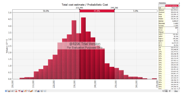
The PERT results gave me a 50% chance that the project would cost $232k, and a 95% chance that it would cost $268k.
The M-C 50% result was also $232k, but I could be 95% sure it could be done for $249k.
So what? As a Client with numerous projects in a programme, you’d be better informed on where to put your money.
I’ve now used bottom-up estimating, PERT, RMS and M-C. All have their pros and cons but the RMS and M-C must be considered the better options. I would argue that unless you have the M-C software package, or Damo to build one on excel, the RMS is sufficient. Both share the same limitation in that they inevitably spit out numbers based on subjective information – garbage in is garbage out. There lies the risk within the risk analysis.
