Archive
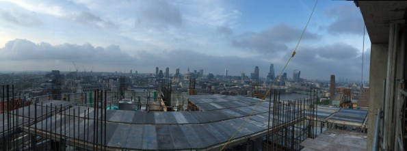
London Skyline
Introduction
After a few weeks working on site and a trip to Borneo it is time for a blog. I’m currently working for Brookfield Multiplex (BM) on One Blackfriars Road (OBR) in central London. BM specialises in constructing high rise buildings or in their own corporate words “We build skylines London/Dubai/Sydney…”.


Overview
BM are constructing a 50 storey residential tower to shell and core status, hotel including fit out and a 4 storey retail podium including all the Mechanical Electrical and Public Health (MEP). Below the entire site is a 3 storey basement which contains all the centralised building services, hotel swimming pool and some very expensive parking spaces.
Shell and Core Status
Shell and core for the tower comprises of the structure, façade, common areas, external works and base plant.
The base plant is mostly M&E and includes:-
- High and low voltage switchgear.
- Transformers.
- Lift systems.
- A standby generator.
- Boilers.
- Chillers.
- Cooling towers.
- Water and fuel tanks.
- Sprinkler plant.
- Building control systems.
- Air conditioning chambers and fans.
- Water and fuel pumps.
- Dry risers.
- Fire detection, alarm and hose reel systems.
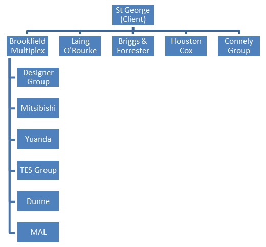
The Client
The client is St George part of the Berkley Group and they are a very ‘hands on’ client with their own project management team on site to manage their own sub-contractors and BM (Principal Contractor). All communication for St George’s subcontractors has to go via the client, which makes it slightly more difficult for BM to effectively manage the entire site. St George are heavily involved with significant developments requiring approval such as jumping the crane, site access and storage, and changing over the power supply from one substation to another.
Role
I have been given the role of Assistant MEP Site Manage and are responsible for managing the installation of the following systems within the Tower and Basement:-
- Condenser system.
- Domestic water.
- Wet riser system.
- Low temperature hot water.
- Low voltage power distribution.
- Heating, ventilating and air-conditioning system.
- Combined heat power.
- Lift systems.
Sectional Handover
The Tower is broken down into sections of 2 to 3 floors and a new section is handed over to the Client almost every 3 weeks. Therefore I’ve been heavily involved with managing the installation and the MEP handover for Section 2&3.
BM have handed over Sections 1-3 and are currently working on Section 4 but the Client has failed to accept any of Sections and it places the liquidated and ascertained damages for the 3 Sections at circa £105k per day. The main issue is the façade and the Client is refusing to inspect the outer façade because they believe it to be dirty and then they have refused to inspect the inside façade because of the outer. Still to be resolved.
View from Level 25
The 5 storey penthouse is still for sale…
Regards
Alex
Trouble At Mill
Trouble at Mill
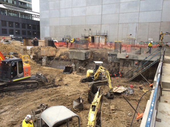
So it has been a while since I have contributed anything. I have been placed I charge of the bulk excavation and installation of rock anchors. Brisbane Casino Towers is now down to Bulk Excavation Level across half of the site and I am supervising the detailed excavation before handing over to the Structural Site ‘engineer’ (the lack of capitals is deliberate). The last 2 months have been somewhat of a rollercoaster and I have learned a great deal from the experience. With the approach of AER 2 it is a good point to review some of the issues that I have had overcome.
Loading Platform
In order to assist with the extraction of soil from the site a loading platform was designed to carry a 47 Tonne excavator. The loading platform was situated on the Hope Street side of the excavation. On 14 April 2016, the braces on the loading platform buckled, halting all loading out of soil and stopping all construction materials from being loaded in. There was a two day delay while engineers could assess the problem and carry out repair work.
The braces buckled due to movement in the secant pile wall that induced a load that exceeded the capacity of the I wrote a TMR on the buckled braces and the stability of the platform down to foundation level. It turns out that at full excavation the wall movement could cause failure and I recommended some alternate tension only restraints back to the secant pile wall as well as a brace back to the loading platform deck to limit the effective length. We held a conference with the designers who were reluctant to admit any wrong doing and just wanted to replace the braces like for like. My PM’s decsion was that we had the sign off from a qualified engineer so it wasnt a problem!
Thankfully the 47 T excavator has now gone and a long reach (33T) has replaced it. The sub-contractor has decide not to risk it (I may have had a word in his ear) so is leaving the excavation high underneath the platform until the platform is removed which has therefore limited the deflection of the retaining wall and the effective length of the plunge columns.
Wallap Analysis. Caution should be used in future projects in the extent to which Wallap analysis can be relied upon for predicting deformations. A safe approach to take is to assume that a wall will deform and design accordingly. Future deformations should be quoted within a range (for example 25-50 mm) to give the appropriate level of understanding to those unfamiliar with geotechnical analysis.
Safety. The Australian approach to safety is similar to the UK’s but different. The Union are seen as the gatekeepers of safety and not the government. Occupational Health and Safety are Australia’s version of version of HSE but they don’t have anything like the powers. Instead Union delegates hold builders to ransom over safety and the approach can seem sporadic at best. BM have a minimal approach to PPE and it is not unusual to see guys laying concrete in board shorts.
 If provoked will strike!
Industrial Relations. Seemingly minor issues are over inflated to put pressure on the state and national governments or employers. The Union effects almost everything in the construction industry and sub-contractors can be blackballed and banned from site even if they have gone through a comprehensive tender process. Walk-outs are common and safety/welfare incidents can be orchestrated to give the pretence for a walk out. To make matters worse if workers down tool for safety reasons they are entitled to a full day’s pay and can even be paid to leave site for a 2hr meeting/march. My site is only around the corner from the Union Headquarters so workers are typically called in for rent a mob demonstrations. It is so bad that you cannot even use the word ‘union’ in correspondence. I had a walk out on site relating to cracks in the secant pile wall when I was drilling the first row of ground anchors. Despite displaying the monitoring results and analysis of the wall the Union delegate held the company over a barrel making various demands before allowing the boys back to work. As a consequence our survey budget has been blown out of the water monitoring wall deflections daily. The only consolation I have is that as bad as they are here they are even worse in Melbourne – you have my sympathy Jo.
![IMG_2697[1]](https://pewpetblog.com/wp-content/uploads/2016/05/img_26971.jpg?w=351&h=468)
First footing in and boom the steel budget gone
Budget. Money is really to tight to mention on this job. BM bought the work from the client in the hope of becoming the preferred contractor. As such we are trying to cut costs all over the place. The decision has been made not to pour blinder and we are laying the footing straight onto the phyllite rock. Incredibly BM have run out of money for steel after our first footing. At tender the consulting engineer estimated 50 Kg/m3 as opposed to the 80-100 Kg/m3. We have blown that in the first mammoth pad footing. Another Brisbane Casino Towers budgeting classic. We are debating the merits of back charging the consultant as we speak.
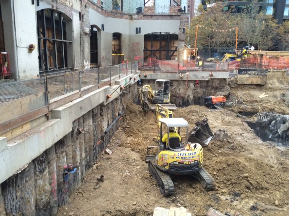
Pile Tolerance. The secant pile wall is the permanent solution for the retaining wall. At a depth 18 m the worst offending piles are off by approximately 200 mm and need to be ‘scabbled’ back in order to fit the ground anchor walers on. This causes an issue as the cover is supposed to be only 150 mm, so far we have not hit steel and I am beginning to wonder if they are reinforced! The piling contractor (Franki) actually haven’t done a bad job as out of the 264 piles on the job only 8 are problem children. I have been told by the Franki that you would be unlikely to see this type of wall beyond 6 m in depth in Europe.
Programme. We are currently 10 days behind programme and Delta are due to pay $15,000 a day for every day they delay the basement handover. So this could be quite expensive for them. BM are less interested in pursuing the Liquidated Damages (LD) are more interested in getting the time back as BM’s LDs to the client for delayed completion are nearly 3 times that. So why did these companies agree to the LDs, well they are part of how business gets done down under and are routinely incorporated into every contract. Normally the LDs are not pursued because there is a small construction community but given the tight budget that BM are operating under they have very little choice.
I have probably written enough for one post but I will follow up with another article on rock anchors and engineering in rock.
Rich/Dam0
PSB![IMG_2714[1]](https://pewpetblog.com/wp-content/uploads/2016/05/img_27141.jpg?w=595)
Calcs are indicative only!! (The brace is 6 m long)
A WHEEL WASH – YES HONESTLY THE STORY OF A WHEEL WASH
Occasionally, I read others blogs and I despair – I am not dealing with safety critical testing, I have not touched out of tolerance piles and certainly not experienced the delights of BIM. Instead I have been busy dealing with the position of a wheel wash… That is correct, the complexities of where to place a giant car wash on steroids. As an aside, the site right next door doesn’t need a wheel wash as NLE use a conveyor and barges to dispose of their spoil. In the process they stockpile all their muck right next to our temporary sheet piles creating surcharge loading that no-one has considered. However, that story is for another blog.
The Problem
Approximately 120 muck away tippers per day, scheduled to increase, when Phase 3 start to excavate the basement levels. A shared access route – Phase 1 (Carillion), Phase 2 (Skanska) and Barhale are all on site (as principal contractors). To further compound the congestion Thames Tideway preparatory works have closed one of the public access roads. Finally, the location of the wheel wash must not clash with permanent structure works. The sketch below shows the access route highlighted in red with the locations of the different Phases and the permanent bearing piles, temporary sheet piles, and permanent secant pile walls.
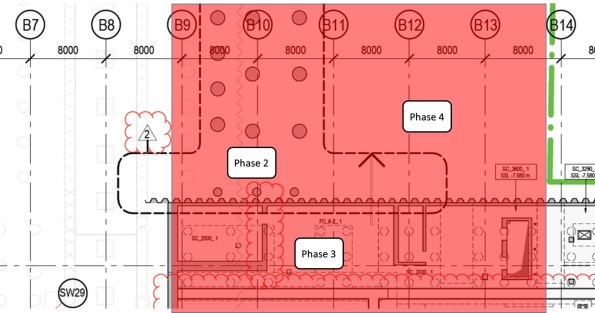
Phase 3 Entrance – Showing the permanent pile locations (red shading access route)
The Solution
My previous blog discussed the requirement for collating detail from all stakeholders. Well, nothing has changed and once again a great deal of my time has been spent arranging meetings. This time it has concerned the interface with the other phases. I have spent numerous hours with McGee (Phase 3 ground works contractor), Bouygues UK methods team (from a construction phasing perspective), Skanska (Phase 2 Principle Contractor), Blu 3 (Phase 2/client’s ground work contractor), Keltbray (Phase 2 sheet piling contractor), Clipfine (BPS site wide logistics and security) and frankly a host of muppets from the clients side… The solution is shown below and as one can imagine this is not an intellectually challenging issue, nor is the solution technically difficult – the draining aspect of this managerial issue is dealing with a group of people who appear incapable of making a decision. It highlights the difficulties of project management on a multi-phased development and is potentially my next TMR.
I am sure you will all have thought of the solution – A single wheel wash directly procured by the client for all Phases but why this has not been done; only the muppets that I mentioned above can confirm!
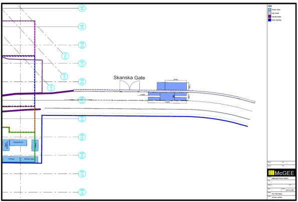 Phase 3 Wheel Wash Location – in the final agreed position (hopefully)
A problem with BIM
Following on the BIM theme from Rich, I thought I’d share a new concern that has arisen in my office.
I work for the Ports and Martine Division at CH2M, one of two global specialist in large container terminals and large port infrastructure. The benefit of being a huge fish in a small client pool is you pretty much win the jobs you want, over price the jobs you don’t want to make big profit or, if you’re busy developers (sometimes) wait until you have capacity. It also means that you’re able to constantly refine what you’re doing and when a new player appears, you can price them out of the game!
There is a weakness in this armor however…….BIM!!!!
The tender team have received a job brief to prepare a bid for a new container port on the Panama Canal. The tender pack contained some BIM images and design of concepts ideas used to win planning authority for the job. The client (a global shipping company) used a US consultant to support planning approval and to help prepare the tender brief. The problem is that the tender brief contains 3D designs and models produced by my office for another job, for the same client, in the Middle East.
So…anyone that has received that tender brief has CH2Ms design, 3D CAD protocols and material information attributed to the model. Luckily in this case the design assumptions weren’t included as it was an early BIM’d project but who knows what will appear next time. Realistically, it’s now just a matter of time until other companies learn enough from the established players to challenge the market.
We (the military) talk about the security concerns associated with BIM but commercially, money is security. At the moment no one quite knows how to address it but the initial thoughts include strengthen contracts to constrain a design to a project (incredibly hard to implement) or limiting the info that goes into data base and how it is linked to the model (counter intuitive and counterproductive). The reality is that no one here quite knows how to tackle this ever growing problem.
Oz NDY – Mirror, Mirror on the Wall…
This blog discusses a couple of examples of key reflections I have made based of my own actions and decisions on the Perth Children’s Hospital (PCH) project and the Vetwest Animal Hospital project. One describes aspects that went well and the other, although an overall successful project, describes simple mistakes that were made. My overall view is that it actually doesn’t matter if something goes completely ‘pear shaped’ (not that anything has) as long as there are learning points that can be realised, whether through self-critique (reflection) or identified through a more formal feedback process. The key importance to the reflection piece is that once outcomes are reviewed, the point of failure identified and then communicated to those parties involved, it is only then possible to go about seeking ways to implement improvements so they don’t happen again.
PCH – Safety Critical Testing
During Ph2 on the Perth Children’s Hospital (PCH) project I conducted a piece of work involving the tender selection process and procurement of a small works package to conduct safety critical testing. The specifics of this can be found from a previous blog, link below.
https://htstrial.wordpress.com/2015/11/27/oz-pch-commercial-and-contractual-tasks/
In summary, JHG had conducted a theoretical study on the suitability of a number of EEG (brain scan) recording rooms to resist RF/EMF interference from various building sources, internal and external. A further stipulation of the requirement was to test for interference concurrently with a live EEG test being underway. The outcome of this study was that although RF specialists, Faraday, suggested additional screening was indeed required in some locations, JHG decided to value engineer out of the programme the works associated to. Aiding JHG’s decision were EEG equipment vendors who made recommendations that was contrary evidence to Faraday’s findings. This is why the client, not wishing to take any chances on medical examinations, stipulated that practical testing be carried out to confirm if screening was required or not.
I conducted a fair amount of research into the requirement and wrote the scope of works used to go to tender. The important reflection piece was getting the detail of the scope of works right and the decision to include Faraday as a tender nominee. This was so that politically and from a presentational point of view, as they were still contracted on the project under another works package, it would have been unjust to exclude them. However, my view was that we needed to remain cautious due to their position, noting that their theoretical study suggested additional shielding was required and I didn’t want that to somehow influence their testing if selected. That’s because the upshot of the results would have huge commercial implications given that all the EEG recording rooms in question were completed and to add more shielding would require a costly strip-out and re-build, no-doubt including other knock-on issues and more cost.
When I left JHG (Nov 15) the tender selection was complete, bar the confirmation interview, and so it was just a case of waiting for the testing conditions to be co-ordinated and ready to start testing. On my recent visit to site accompanying the CI, the building services manager, my old line manager, informed me of the outcome of the testing. There were a few minor interferences from external systems into some of the rooms; these walls now need to be lined with extra shielding. However, worse still when the live EEG recording was underway there all rooms showed massive interference from something inside the rooms. This has now sparked a new investigation to establish the cause and resolve it. The other key reflection point here is that I made sure in the cost break down section of the works included subsequent rounds of testing should the initial results indicate a failure. This was why we selected EMC Services as the preferred specialist consultants as they were the cheapest over all three rounds of testing (the maximum required) and didn’t charge for additional provision of reports.
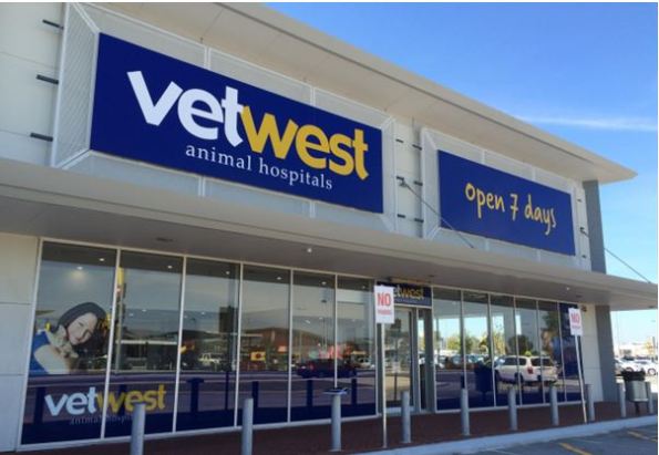
NDY – Vetwest Animal Hospital
Like the first example I have already discussed my involvement in my first project leader role on the Vetwest Animal Hospital project, see link below.
https://wordpress.com/post/htstrial.wordpress.com/11190
Now complete I conducted a feedback session on site with the construction managing contractor, Perth Citi Fitout (PCF). The reasons I wanted to do this were threefold: understand what went right, wrong or what could have gone better in order to improve where needed for the two subsequent projects that I was informed we’d most likely win; allow me to properly reflect on my first project leader role for self-appraisal; and finally to retain any lessons learnt to ensure corporate knowledge is not lost when I leave.
Overall the project was a success, testament being a number of conversations with PCF’s managing director who has praised my work and co-ordination of project leading and is looking to conduct two further Vetwest projects with NDY as the design consultants.
The biggest issue, which wasn’t really that big a deal and which was easily resolved and done so promptly, was the missed deconfliction between the supply air diffusers and light fittings. Although the lights themselves were not included in the scope of works we did have the CAD file of the ceiling plan. It wasn’t until the lighting sub-contractor began installing the lights did it become apparent that the diffusers were already installed and in some but not all cases they were where the lights should have gone. A phone call to me explaining the issue was enough to quickly go about resolving the issue. This was a chat to the CAD department requesting that the electrical ceiling layout and mechanical layout be deconflicted. There were a few knock-on effects, mostly being a number of supply air grilles that required blanking plates to avoid cold air hitting and dumping down wall surfaces in some of the smaller consulting rooms where it would be noticeable; also, the time to source and fit them. One unaffected outcome was that moving the diffusers by a ceiling tile or two was practically very simple as mech sub-contractors love to use flexible ducting running off the indoor units and they always allow a metre or so spare capacity.
The reason this issue slipped through the net was due to me making an assumption that the CAD draughty would have done this check when overlaying the various discipline layers in Revit – lesson learnt, don’t assume, ask and get confirmation.
Other smaller issues were some of the technical specifications of fixtures and furnishing were the incorrect type, for example, the back of house laundry sink didn’t fit in the cabinet as it was too deep and the sensor activated scrub sink taps were apparently the wrong type. This was again a case of not checking that the tech spec brochures provided were correct, although you could argue that this should have been a check conducted by the managing contractor when they were reviewing the design drawings. Another issue, from an aesthetic point of view, was the medical oxygen supply pipe running from the cylinder cage outside to inside was installed running up the inside of the wall from ground level to through the suspended ceiling. The core through the outer brick wall should have been located in the ceiling void and the pipe run down the outside of the wall where no one will see it. Having chatted this through with the hydraulic design engineer he said he accidently omitted the pipe dropper symbol on the CAD dwg and so the hydraulic sub-contractor literally followed the dwg – which I suppose you can’t blame him for but maybe he might have seen this type of arrangement before and should have least had a chat to the on-site PM.
As part of the same feedback session I also had the opportunity to ask questions of the clinic team manager, as Vetwest were moved in and the practice was in full swing. Astonishingly, none of the staff were consulted by the Vetwest project manager. She was shocked when I told her that this level of stakeholder management was an absolute must and should have been conducted. It transpired that on her initial induction walk round her and her staff pointed out a number of incorrectly located equipment including the unnecessary installation of a hose cock tap and floor waste bucket trap for the Cattery. Their SOPs are to simply sweep out. There was also the requirement to fit an extra oxygen pipe branch into the X-Ray room. This was something I recall having a telephone conversation about with the Vetwest project manager and remember getting it confirmed in writing. It was to be included then it wasn’t then obviously it was. The issue with it was that the terminal out the wall was in the wrong location for their trolley to connect onto and reach the dog/cat when positioned on the X-Ray machine.
A lot of this is down to a lack of internal Vetwest stakeholder engagement and is a valuable lesson learnt.
What Now?
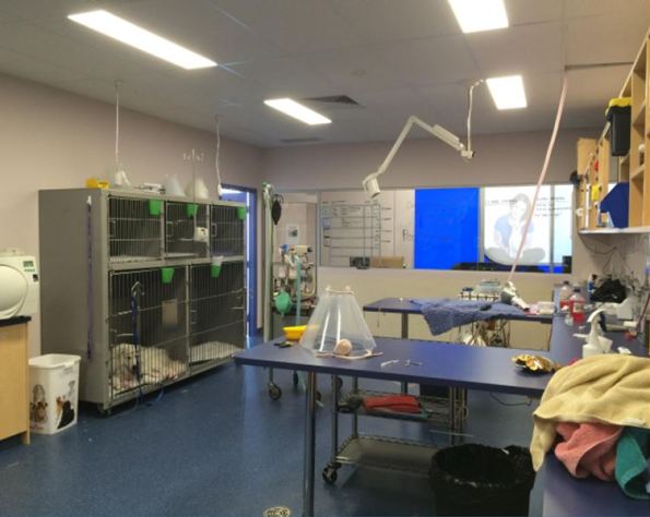
Having conducted the feedback session I am presenting these findings to the design team involved in the project and therefore closing the loop on the continuous improvement process. It also highlights the issues mentioned above and aims to ensure that whoever project leads the next two projects, they understand where to find particular information. An example being: the Australian Veterinary Association Accreditation Scheme that Vetwest was seeking to highlight to their customer base and regulatory inspectors of their attainment of best practice animal care. I achieved this through understanding the technical implications of accreditation, like ensuring cleanliness standards are as high as possible. To strive for best practice here meant installing HEPA filtration in the Surgery room.
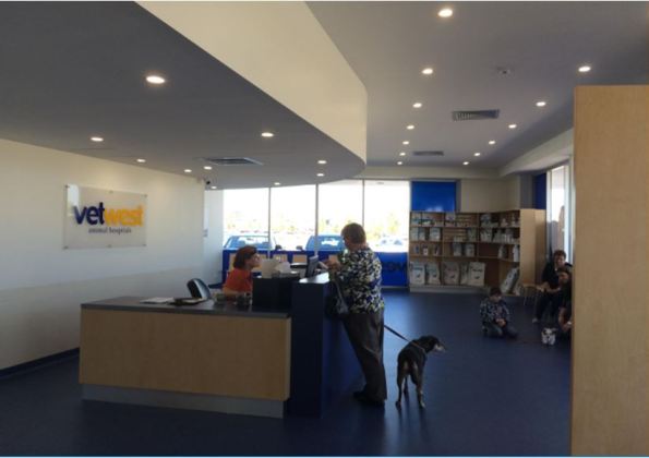
From this….
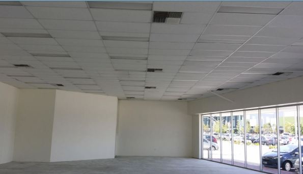
…to this.

In Other News
We’ve seen a fair amount of aquatic life, and swimming with Whale Sharks was definitely one of the highlights of our time out here.

The value of 3-D Modelling and record keeping.
The majority of my time on phase 3 has been focussed on working at the London School of Hygiene of Tropical Medicine (LSHTM). LSHTM’s building was opened in 1929 and has undergone several overhauls and extension over the last 80 odd years. This combined with the fact the keeping of record drawings seems to have been considered as an embuggerance as opposed to good practice made working out how I could modify their systems a bit more tricky than it needed to be.
If LSHTM were to be considered as left of arc, I have more recently been working on a project at the right of arc end of the spectrum; the re-modelling of Circle Reading Hospital which I have previously blogged on. The scope has now been expanded slightly. The client now wants to change the use of a waiting /reception area to a group activity (physio) room. This has implications with regards to the level of ventilation required to the space and the cooling load required. Although not contractually completed to a specific BIM level, Circle Reading was designed in Revit with the associated Navisworks models still in existence. This has allowed me to quickly interrogate the model via a desk top study to see what is supposed to be in the ceiling void and work out what space and services we have to play with. The client’s F&M team have also been very good at keeping records, so I have been able to interrogate the original main contractor’s commissioning results and compare them against the original design specification and schedules. From there it has been a case of applying the necessary calculations to work out what the new load is, confirming if the existing system has sufficient spare capacity and in what areas modifications need to be made to allow my proposal to work. Of course all this would have been possible without the information I was given, but it would have required hunting around the building for equipment details, getting airflow velocities and getting into ceiling voids to see what is actually there. The use of 3-D modelling and good record keeping has allowed me to meet the client’s intent of getting a proposal out cheaply and quickly. There will be significant caveats applied to my design note as I’ve not confirmed my design start point on site; however, the client is aware of this risk and happy to proceed.
Poplar Island
Poplar Island
So, I’m actually on site now doing some engineery type things! However, for obvious reasons taking photos is proving to be a bit problematic. In order maintain some sort of presence on the blog, welcome to my new two part mini-series, which I’ve catchily decided to call “interesting things that USACE do that the Royal Engineers don’t do”! Location one: Poplar Island.
Poplar Island was/is an island in the middle of the Chesapeake Bay, approximately 18 miles south-east of Annapolis. Historically it was settled in the 1630s, and had a permanent population all the way up until around 1920. However, due to a number of reasons, mainly human mismanagement, but also natural erosion, the island shank from approximately 1000 acres in the 1840s to less than 5 acres by 1990, and was set to disappear altogether had someone clever not decided to do something about it. A vast amount of material is dredged out of the Chesapeake Bay each year in order to keep the shipping route to Baltimore open, and some other clever person decided it might be a good idea to use this material to try and stabilise and rebuild the island.


Poplar Island During Construction (bottom photo is probably 2 or 3 years old)
What has been achieved since then is one of the best examples of ‘environmental’ engineering that I’ve ever come across. Since 1998 USACE have created 1140 acres of ‘new’ wildlife reserve in the middle the Chesapeake Bay. The technique they use is to create a series of waterproof bunds that divide the ‘island’ up into manageable ‘cells’. They then pump millions of litres of sediment rich slurry into the cell they are working on, allow the slurry to dry out, then repeat the process for as many times as is necessary to build up the amount of material required for the habitat they are trying to create. The two habitats being created on Poplar Island are ‘tidal wetlands’ and ‘upland woodland’ in about a 50:50 ratio. When we visited last month a number of the tidal wetland cells had been completed, but all of the uplands cells were still ‘work in progress’ because they require the ‘finished floor level’ to be significantly higher!

Completed ‘Tidal Wetland’ Cell
Whilst generally successful the tidal wetland cells that have been completed so far provided some challenges, mainly for the biologists creating the habitats. Initially the channels linking the ‘inland’ water and marshes to the bay were too small and discouraged the large predator fish species from entering which led to an unbalanced ecology. Subsequent cells have been designed with larger openings and have been more successful.
So far the island is frequented by around 175 different species of birds, including ospreys, and terns. The terns are interesting; despite having over 1000 acres to choose from, they are habitual, and so return every year to the same tiny section of the island that they have always used! The biologists are hoping they’ll eventually get the idea, but so far they seem happy on their little patch of mud. The ospreys are currently living on ready-made posts, but the plan is for them to move into the trees once the woodland sections of the island are far enough advanced. A significant colony of terrapins has also established itself on the island which the staff are particularly happy about!
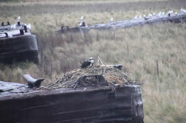
Local Inhabitants (Osprey)!
From an engineering point of view project is interesting, but really relies on the sheer volume of material for success. Now that the techniques have been tried and tested there is little in the way of complicated problems to be solved, and the process is very repetitive. The one issue the project did have was when one of the bunds was breached/overtopped during a particularly bad storm early in construction. This led to a significant amount of material being washed away and the bund having to be reconstructed before work could re-commence.
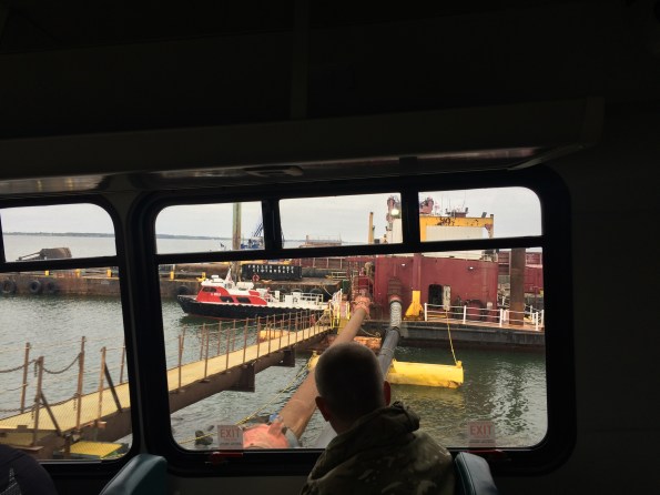
Henry’s Head (and the pumping station from where dredged material is pumped to the cells)
The total cost of the project is set to be around $800m, of which 75% comes from the Federal Government and 25% from Maryland State. The scheme has proved to be so successful that plans are well advanced to add a 575 acre expansion to the north of the island which would take the total area to approximately 1700 acres. The ‘construction’ phase is currently due to be completed in 2029, however significant management would be required beyond this date. If only the Royal Engineers were trusted to deliver something like this!
Other News
I’ve inherited three Officer Cadets! They were recently sent out on a two day ‘recon’ to gather ‘intel’ on some local critical national infrastructure! I very much enjoyed listening to their backbriefs and grilling them ‘Warfare Wing style. The next “interesting things that USACE do that the Royal Engineers don’t do” blog will be on the Raystown Dam and reservoir, an equally colossal project!
AEH.. “INFO ONLY”…
Hello folks, just a short, sharp snip it of some interesting bits going on in the design office here in Sydney’ M4 East motorway project. Clearly, those two terms are rarely linked but today I think they make the cut.
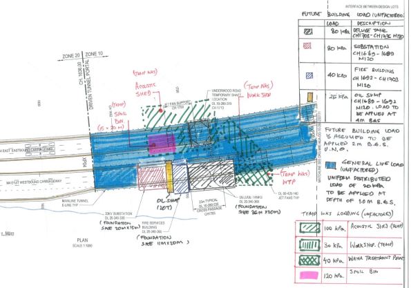
“Info Only” – Interesting proposal by AEH (AECom & Hyder JV)…Clear lack of comms…
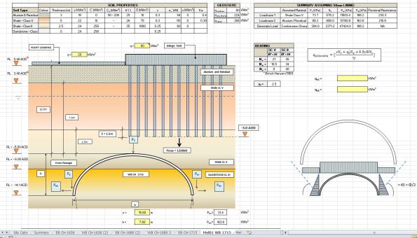
Attached below are two images. 1. Plan of mainline tunnel with surface loads indicated. 2. A screen shot showing the proposed AEH foundation design within a section of mainline tunnel I was analysing for crown loads and canopy tube design. The confliction with our 4m rock bolts emanating out from the tunnel lining is not show.
AEH released their package today for various permanent M&E structures to be installed above the tunnel. I’m in the process of assessing the shotcrete lining thickness and elephant foot dimensions based upon surface loads, overburden, relaxation, ground water etc… The original idea was to install a raft foundation which we were more than happy with (10.5m above). The fact that they now wish to terminate their piles 2m above the crown of the Westbound mainline tunnel is one thing… the fact that they only put Macmillen Jacob Associates (MJA) down as “INFO ONLY” on the cross discipline review form is another! Unbelievable…
Presumed next step..Cost analysis to compare the additional excavation + lining thickness + time+programming required to support new proposal vs an reconsidered AEH foundation design. Interesting stuff but clearly not my main priority at the min…
108 Update
Time for an update on site progress at Australia 108. Lots of progress on site this week. 90% of the piles caps are complete and we have begun the excavation to Basement Level 1. We are 38 days behind the site program due to various issues and delays with the piling as well as lost days due to weather.
The most recent big issue is one of out-of-tolerance as-built piles. The Australian Standards allows for 75mm tolerance however due to the risk in the piles, the designers have allowed for 150mm. So what do you get when you discover that a 2100mm, 80MPa pile with a design axial load of 111.6MN, moment of 16.5MN and shear of 2MN ends up being 401mm out of position? An increase in moment to 49.9MNm; the design effect has greatly exceeded the design resistance of the pile = big problem! The engineers are currently looking at rectification methods involving large transfer beams in lieu of individual pile caps and transferring the addition moments generated to the other piles and the core if necessary. It is estimated to be at a cost north of AUS$400k = 200GBP +. There have been 12 piles over the specified tolerance and with the exception of one, the others have luckily had adequate capacity to resist the additional moment due to the redundancy in the pile with minor rectification measures being introduced to the ground beams.
My TMR is looking into the risk management strategies of deep foundations so once I’ve finalised it, I will post a very abridged version highlighting our issues and probably causes. I know a few of you are soon to commence piling in your projects and can benefit from hindsight of some really simple errors that have been made on this site – most of which could have been easily avoided.
Here are a few pictures to keep you up to date with progress on site.
View to the East

View to the South – excavation of the core piles has begun consisting of 16 x 1800mm king piles with 600mm dia CFAs between

View to the West – secant retention wall to protect a 60 yr old heritage facade at the northern end of the site
View to the North West – northern retention wall and one level excavation
And for those of you with beady eyes it will not escape your attention the 3+m high vertical face of the southern end to the excavation. Fine grained soils, 30t excavator rolling back and forth on the top of it and no retention or batter. We’ve also had a lot of rain recently (for Melbourne anyway – the news reported a taxi getting flooded out to mid-point of its wheels!!!!!) I have raised this concern to the powers that be and it has already been mentioned to the subcontractor who have chosen to continue as it – because they do it all the time. BMC are allowing them to continue (cynical view – because any changes will slow down progress.) They have instigated no one to walk at the foot of the wall yet people are still walking at the top of it. I’m astounded that they will stop work for the slightest speck of rain because of the potential hazards created, yet they will let people walk along the top of an unprotected excavation. And they are constantly telling me how at the forefront of H&S they are. Barking!
Progress on 12/5/16


Progress of 13/5/16


Circle Reading Remodelling
The most recent work strand I’ve been involved with at BWL is the re-modelling of a private hospital in Reading. The hospital is owned and run by Circle who have a long term relationship with Bryden Wood Ltd (BWL). The requirement to re-model is based on Circle wanting to go into a joint venture with a German health care provide called Vamed. The plan is to hand two of the four floors of the existing hospital over to Vamed. This requires a number of rooms on the second floor to be changed. The client’s drivers are cost and time. Initially BWL priced the job at £90K for an architectural and M&E design role. The client currently doesn’t have a formal agreement in place with Vamed, so the real driver is to get the work done in order to seize a potential opportunity whilst spending as little cash as possible. This has led to a reduction in BWLs fee to £10K, which means BWL’s outputs are limited to a concept design which will be taken forward by the main contractor. I can understand the financial pressures the client is under, but it seems a little odd that the first interaction in a future strategic relationship is being done on a shoe string budget.
From an M&E perspective there are 2 engineers working on this project (1 electrical and 1 Mechanical). The limited budget means that this work needs to be turned around quickly, which is great for me as it’s another project under my belt for CPR.
What has my role been:
As the sole mechanical engineer working on the project I’ve been responsible for checking the implications of the changes of use on the mechanical system. This has entailed:
- Producing room data sheets for each area to define the environmental standards that need to be met (ventilation rates, temperature, acoustics, etc.)
- Using the data from the room datasheets to calculate loads for each area (cooling, heating, ventilation, domestic cold water, domestic hot water)
- Identify the best possible way to meet the new demands. As an example active chilled beams are utilised to provide comfort heating and cooling, where possible these have been retained, but where loads are too great or not close to the current distribution network other solutions have been provided.
- The impact of these solutions have then been confirmed: basically checking pressure drops in pipework and ductwork and making alterations where required.
- Engaging with my electrical and architectural colleagues to ensure that our designs are co-ordinate.
- This has then been pulled together into a scope of works, including mark-ups of existing schematics and schedules of new equipment so that the contractor can price the job and take the design forward.
All in all a good little project that has given me some solid B and D competencies. It’s probably worth noting that I found the calculations involved in conducting this work to be much simpler than those conduction for phase 1: phase 1 more than prepares you for the technical aspects of phase 3.
