Archive
The Devil is in the Detail
Phase 3A must construct three large temporary bridges that provide access through our site – both for adjacent phase’s construction traffic and future residents. The 3D CAD model below provides an illustration. I have responsibility for bridge 1. The bridge section spans over 54m and it has two decks of 24m length at either end. It will be suspended 18m above formation level (when we eventually dig down to basement 3 level).
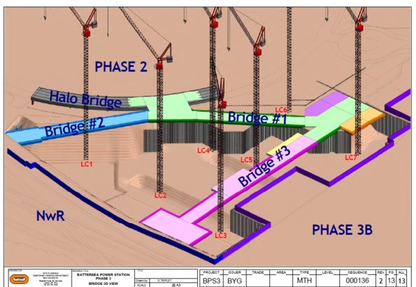 Temporary Bridge Structure – 3D CAD Model
The Problem
Bridge 1 must be in place to allow residential occupation of Phase 1 (Carillion’s site) in Q4 2016. As a result, the client’s driver is time. Unfortunately, the temporary bridges have been designed in isolation to the permanent structure and only considered on plan. As one can imagine this situation has created many clashes.
The Solution
The Devil is in the detail and the solution requires all the stakeholders input. De-confliction is the name of the game and the majority of my time has been spent in meetings trying to work through solutions. The greatest difficulty lies in the area of the temporary bridge deck supports. These ‘dolphins’ (the nomenclature on the drawings) consist of piled foundations with high level pile caps that support the bridge deck. The drawing below illustrates the initial design with uniform spacing (coinciding with the deck spans).
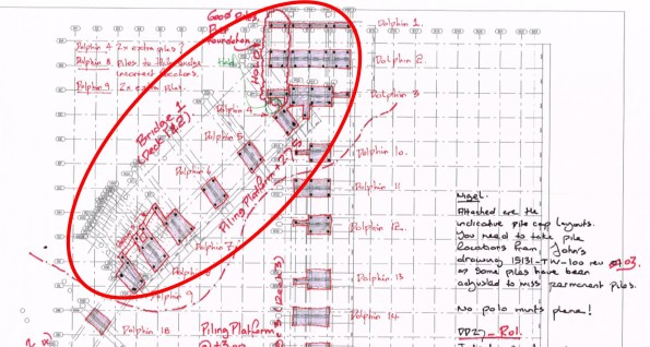 Bridge Supports – Initial Design (relatively uniform supports)
My task has been to knock heads together to come up with a mutually beneficial solution for all. I have convened meetings with the temporary bridge designers (McGee), the permanent structure designers (BuroHappold Engineering), the piling contractors (BBGE), the M&E designers (Chapman BDSP) and the construction sequencing team (Bouygues UK). The outcome of these painful liaison meetings can be seen below. One reason these meetings are so painful is because still no-one has signed a contract. Whilst not the most exciting Blog post the two photos represent a couple of weeks work and provide an idea of the small victories won. The next stage is to attempt to reduce the size of these temporary bridge supports…
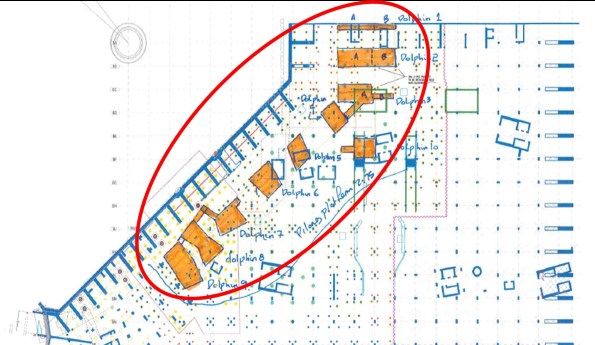 Bridge Supports – Post De-confliction (variable shaped supports)
Wasted work
In my last blog I mentioned that there had been a bit of a question 4 moment with regards to steam at LSHTM. This was based around the client asking me to explore other opportunities with regards to steam distribution.
In mid-March I took isometric drawings produced on Revit to the client for approval on the distribution strategy. Prior to conducting the work in Revit to produce these drawings I had discussed the proposed route with the Project Manager (PM) within the LSHTM estate’s team. The route I was proposing was based on taking steam from one side of the building where it was being generated at high level to where it was required on the other side of the building via an external route. This was because I had been briefed to minimise the amount of disruption to the building which would be fully operational during the works. I discussed this route with LSHTM’s PM and even took him to look at it with a possible contractor for comment on the buildability of my proposal. Having gained buy in of the client I proceeded to continue with the work and produce the required drawings in Revit, which took me approximately 1 week. What I failed to do was quickly mark-up a drawing by hand and send it to the client for them to approve formally. It was then at the meeting in March that a more senior member of the client team expressed disapproval with my proposal and asked me to look at another option. This is frustrating on a personal point of view as it is duplicating my work on the same experience and there is little competency experience to be gained from producing drawings in Revit (although being able to use Revit can go towards my A competency). It was also a missed opportunity from a BWL point of view. Because BWL are attempting to develop a relationship with LSHTM there was no resistance to LSHTM’s suggestion from my director. Probably in part because with me doing the work there is limited cost to BWL. If I had sent a mark-up which had been signed off by the client there is more chance that my time wouldn’t have been wasted in that the desire to explore other options could have been looked at prior to me doing the work in Revit, or if it had been approved I would have had an audit trail to fall back on. I could have more rigorously demonstrated that I had developed the design in good faith and that the proposal being made to consider another route was effectively a variation and required an additional fee. Whether my director would have wanted to do this is questionable, but it would have at least given BWL the option and has certainly taught me valuable lesson.
Design of Structural Elements Against Explosive Blast
I mentioned in my first blog that the construction of the ground floor slab is considered a critical milestone. With that for context you would assume that everything possible is being done to ensure the concrete pours on this slab are completed on programme. This brings me nicely on to the topic of this blog.
Early last week, only 60 mins before a significant concrete pour (50m³) was ready to begin on a key part of this slab, an issue was identified during final reinforcement inspections. This caused a fair amount of aggravation and stress on site between the consultant engineers and concrete package sub-contractors .
The issue relates to the column in Fig 1.1 and in particular the depth of fillet welds between the web and flanges. The column protrudes through the GF slab and was scheduled to be encased in concrete up to GF level as part of this pour. The engineer consultant, during his final check of the slab reinforcement bar, identified an issue with the welds on the column that stopped work until the senior structural engineers at the design office could be consulted.

Fig 1.1 – Incorrect Weld Configuration on Column L8
As I know the audience reading this blog adore explosives, and in particular blowing up military bridges on exercise, I thought they might be interested to hear that many of the structural elements have been designed to resist an explosive blast detonated at very close proximity.
Robustness in a building is usually achieved through one of a number of approaches. The most common is to design alternative load paths in case a structural element fails. On this project however, due to a late notice client dictated design change, this was not a viable approach. Robustness is therefore only provided through the alternative ‘protected element’ method. By this I mean key structural elements are designed with adequate individual robustness and additional protective measures (i.e. encased in sacrificial concrete or steel) to ensure they do not fail even when exposed to the designed worst case load condition.
In this particular column the weld design has been specified for this worst case condition. Unfortunately the column was not constructed in accordance with the design drawings. To provide suitable shear resistance in this element, the Blast Engineering Consultants specified a 70mm multi run fillet weld along the full length of the column to the base of the ground floor slab. As Fig 1.1 shows, the steel contractors only installed the fillet weld from the top of the column to the first web stiffener, leaving a considerable length of this column with minimal 15mm deep fillet welds. To try and understand the magnitude and context of the site engineers concern I tried to conduct some very basic analysis of this section.
In the first instance I modelled this problem as simply as possible and effectively considered the column as an I beam bending in one axis with an 8.6MN worst case vertical shear reaction force. To be clear from the outset, it will become apparent later in the blog that this model is far to simple for the complexities encountered in this problem.
Students on the civil stream will fondly remember the “Say It” equation which allows calculation of shear stress along a particular plane at any point in a bending beam. One of the key components in this formula is the thickness (b) of material providing longitudinal shear resistance along the assessed shear plane. The greater the (b) the smaller the shear stress. In steel plate sections a fillet weld exists to simply transfer the shear stresses from the flanges to the web so that the top and bottom flange can work together as a single beam (ie they know about each other). It’s worth noting that because these columns are steel plate girders, there is no monolithic connection between the web and flanges to provide an additional contribution towards this shear resistance. I have simplified the diagram to sum this up and illustrate why the reduction of this weld from 70mm to 15mm might be a problem.

Fig 1.2 – Simplified Column Section Model
Diagram A shows the steel column, as installed, below the web stiffener. Along this length the fillet weld installed is only 15mm in width each side of the web, this provides a total (b) of only 30mm. Diagram B shows the steel column where the fillet weld has been correctly installed. This weld, 70mm on each side of the web, provides a total (b) of 140mm of resistance along this shear plane.
In accordance with BSEN 93-1-8 Para 4.5.2 you actually need to use the effective Throat thickness (a) of each weld in this calculation (This provides a conservative estimate) which can be acquired with some simple trigonometry. I calculated weld throat values of 10.6mm and 49.5mm for case A and B respectively. These figures are then doubled through most of the calculations because we have a weld on both sides of the web.
I then plugged these dimensions and the known constants into the “Say It” equation, with the two different welds considered, to analyse the varying shear stresses induced as a result of the designed maximum blast load occurring on the column:
Calculation Details:
Max Vertical Shear Force on Section Vz = 8.6 MN
Second Moment of Area = 32.77 x 10⁴ mm⁴
Distance from NA to Centroid of Area above shear plane = 200mm
Area above Shear Plane = 38400mm²
Width of Material under shear (Weld Throat): Case A = 21.2mm
Width of Material under shear (Weld Throat) : Case B = 99mm
After I’d run the calcs through using the information above I got the following shear stress values through the welds in each case:
Shear Stress in Weld:
Case A: 950.7 N/mm²
Case B: 203.6 N/mm²
I also calculated the greatest shear stress likely to be seen in the I section for both examples in order to allow further comparison. We know this appears along the NA where the web in this case is 60mm. I ended up with shear stress values as below.
Shear Stress along NA – Web:
Case A: 371.1 N/mm²
Case B: 398.78 N/mm²
When you look at this logically, it raises a few interesting points. In Case A the shear stress expected in the weld is over 2.5 x greater than that seen in the web on the NA. Therefore, when affected by the blast load, the weld is likely to fail long before the web of this section.
In Case B however the weld sees an expected stress that is approximately half the shear stress seen along the NA in the web. In this case it is likely the web would fail before the weld. This suggests the 70mm weld is therefore larger than actually required. Generally a design throat thickness of an I section, doubled to account for both sides of the weld, should be a similar depth as the web thickness on that section. Any additional weld depth is most often unnecessary because the failure risk is transferred to the web.
Using BSEN I then checked the actual permissible shear stress in each weld. In both cases I calculated this to be 230.9 N/mm². When you compare this to the expected stresses, it is clear that the fillet weld in case B is capable of carrying the design stress of 203.6 N/mm² but not the 950 N/mm² of case A; clear indication that the 15mm weld is grossly under strength for the worst case load condition assumed in this model.
I mentioned that my first model kept this analysis as simple as possible. In reality the problem is considerably more complex for a number of reasons. Firstly, I assumed the blast occurred directly perpendicular to top flange. Blasts occurring at different angles to the section would undoubtedly affect the results. In addition to the 8.6MN vertical shear reaction load I considered on the section there is also a 9.5MN axial load from the weight of the building applying a compressive pre stress through the column. Furthermore, the complex nature of the dynamic/impulsive blast load on the section is also far more challenging to categorise; it is affected by numerous variables including charge size and type, stand off, ambient pressure and charge proximity to the ground, amongst others. The response of a steel column to a blast load is also influenced by stiffness, its dimensions, vibration period and strain-rate. The point being, this is far too complex to analyse with such a simple model.
What is very clear is that no one in the project team seems to understand the science or engineering behind the blast design analysis. All we know is that there is a specified design explosion and the consultants tell us the size of elements required to provide robustness. If I can learn about the science and engineering models applied in the space and time between the immediate explosion and its impact on the column I will probably know more than most of my immediate colleagues and have a potentially interesting thesis topic. Fortunately I have managed to arrange a visit to the blast design consultants test facility in the coming weeks to see first hand how they model their problems to produce the design output. With any luck they will also let me blow up some steel columns in the name of thesis or TMR research.
In practical management terms the project team on site got irritated by this problem because the column had been in position for three weeks before the issue was spotted. Had we employed more thorough quality assurance inspections, it is likely this issue would have been picked up earlier.
This incident is also a potential indication of a more commonplace issue. From a brief investigation I am certain that the column was inspected and signed off imediately after installation. The likely problem therefore, I’m speculating only, is that the individual who inspected and signed off the steel either didn’t do it thoroughly, made a mistake or potentially didn’t know the detail of what they were looking for when completing this process. Which raises the question of how to best ensure QA inspections of completed work are only conducted by individuals capable of understanding the technical importance of the details contained on drawings and specifications.
Once I have got more information on the modelling methods used by the blast consultants I will attempt to publish another blog on the subject and its affect on my own analysis of the issue identified.
Silver Spoon, Wooden Spoon
My design attachment has been very different from what I expected (I blogged about this a few weeks ago).
It seemed as though I had been given the silver spoon with the design manager job for the Calder Highway Overtaking Lanes (CHOTL). It doesn’t give me quite as much depth as I was hoping for, but the breadth is there in terms of attribute achievement. But it would seem that with my silver came a wooden one too…
I don’t have much else to focus on in the office (anything, in fact). Managing the CHOTL project has busy days and quiet days. As a Contractor seconded to GHD, I have to fill in a weekly timesheet that charges to whatever job I am working on. I was ‘sold’ to GHD by JHG, promising 40 hours per week for them to do with me what they will.
The issue I raised this end yesterday is that I am here until the middle/end of June. The estimate for the CHOTL project only allows 150 hours of my time (3.5 weeks full time). So the more time I invest in my project (or charge to it, at least), the greater my chance of going over budget. If I clock in fewer hours then GHD is ‘not getting their money’s worth’. Seems a little short sighted sticking me on a modest lump-sum agreement project with a 12 week timeline and when I can only apply myself for a third of it.
If I was GHD, I would be frantically trying to find a bigger project with a bigger Client to charge me to.
CPD/what I wish I’d known about the thesis
CPD/what I wish I’d known about the thesis
This is just a quick blog to follow on from the very useful blog by Rich Garthwaite on CPD and then talk a bit about the thesis.
ICE events.
There lots of presentations at One Great George Street which generally start at 18.30 so can be a good excuse for leaving site at a sensible time. There are a few annual talks which I have attended and thought were interesting for those in London or for those not, logging in online.
Joint Professional Meeting between the Royal Engineers and ICE, this year on 28 April 2016.
James Renie Medal – this is the top 3 successful CPR candidates from the previous year vying to demonstrate that they best reflect Renie’s principles.
ICE tour and history presentation. I did not hugely rate the presentation but having been to a few more things since, knowing a bit about the background to the creation of the ICE as well as seeing more of the institution’s home is only of benefit. The tour is by all accounts good.
Flemming Award, Smeaton lecture and John Mitchell lecture. These annual lectures which cover a geotechnics (and other topics) and two were recorded.
https://www.ice.org.uk/eventarchive/the-2015-fleming-award-competition
https://www.ice.org.uk/eventarchive/smeaton-lecture-2015
For those more geotechnically minded the Rankine lecture at Imperial College is pretty much the top end of geotechnical discussion and worth going along to hear about current themes in academia and industry. Next year (March) will be an overseas presenter. Don’t under estimate how popular it is!
These all help both towards CPD hours as well as attribute 9 in terms of participating in ICE events.
Thesis
The second point of this blog is just to point out some of the ‘what I wish I’d knowns’ regarding the thesis writing. Perhaps something others have found similar things, or not. I have got 4 points. Might be useful for Phase Twos now, albeit at preparation stage only.
Format. Slightly dull point but if anyone has resisted making use of the word styles, auto-format templates I would strongly encourage getting on board early. With 4 x TMRs, 5 x AERs and a thesis it will save hours on formatting if all of the lists of contents, figures, tables and most usefully references are all done for you. Also internal referencing within the document becomes easy as the document will self update. Highly recommended.
Timing. I found there was no time between TMRs, AERs and site work to start writing the thesis much before Christmas – clearly possible, you would just have to be more organised. Therefore the likelihood is you may choose a topic related to site and be writing it when not on site. However, it will help if you know what it is you are doing much before Christmas to allow primary data collection – as per the coursework timeline.
Primary data collection. For the reason above, if doing a site related thesis, collecting primary data from site is critical. If it’s tests on concrete or monitoring data or something else, I would advise deciding in sufficient time to get the information you need. You probably won’t manage to capture it all, so get all the details of people you might need to pull favours from afterwards.
Keeping a record. The biggest thing I am finding is not remembering quite what happened and when it happened. This is practically in terms of why some of the primary data is as it is (so I recommend keeping a site diary for sole thesis purpose of recording activities relating to the data). This is also cerebrally; trying to remember what you discussed or wrote on a notebook, 5 notebooks ago, did not work so well for me. I would have kept a better electronic record (text, photos,) of discussions, events and even thoughts to help remember everything when coming to put pen to paper a few months later.
Just my thoughts anyway.
Ground Improvement through Jet Grouting
Jet Grouting
Jet grouting is a construction process which employs a high kinetic energy jet of water to break down a soil formation into suspended particles and mixes the in-situ soil with cement grout. This process of hydrodynamic erosion of the soil and mixing forms a soil-cement mix which has improved properties. There are three distinct phases to the process (see Figure 1):
- Breakdown of soil formation using high-pressure jet. A borehole (90-150mm) is drilled to depth and fluid is pumped at a pressure >450bar to the base of the drilling rods to breakdown the soil formation.
- Introduction of grout. The rods are rotated slowly as they are extracted from the borehole and cement is pumped from the base of the rods simultaneously. This creates a column of soil-cement mix, evenly distributed through the treated volume. This phase of the process uses a computer to control to extraction speed, rotation, grout pressure and grout flow.
- Displacing of excess material. All excess soil-cement mix exits freely to the top of the borehole and removed. The pressure is stopped 500mm below ground level.

Figure 1 Jet Grouting Technique
Requirement at Australia 108
The scope of works for the Australia 108 project was to provide a jet grout plug from RL -7.0m to RL -8.0m to act as a strut against the core retaining wall and reduce estimated deflection during excavation. This would enable a 6m deep excavation from RL -1.0m to RL -7.0m without the requirement for walers and struts. It would also serve as a plug to reduce water ingress into the excavation. In total 106 jet grout plugs were placed varying in diameter from 1.4m to 2.2m, (see Figure 2). The ground conditions from RL 0m to RL – 17.0m is Coode Island Silt which is soft to very soft silty clay with high plasticity. The GWL sits at RL 0m. Menard Bachy secured the contract for these works.

Figure 2 Jet Grout Column Arrangement
Trial Works
The strength of the grout mix will be tested to confirm that 2MPa has been achieved at 28 days based on cubes sampled daily from the spoil return. It is possible to core the jet grout plug in situ and test but it is preferrable not to. Instead trial works were done prior to production of the core plug. The aim of the trial was to allow commissioning of the grout batching, pumping and drilling equipment and to ensure that the columns are consistent with the design assumptions.
Six jet grout columns were arranged as per Figure 3 to achieve overlaps of 400mm between 1.4m and 2.2m columns, and overlaps of 300mm between 2.0m and 2.2m columns. The trial columns were installed at the same depth approximately 10m away from the permanent location. The overlaps were cored and visually inspected to check for integrity prior to commencing the permanent works (photo of core sample at Figure 4). It was assessed that close to 100% of the Coode Island Silt had been replaced by grout and that the overlaps have been achieved.

Figure 3 Trial Column Arrangement
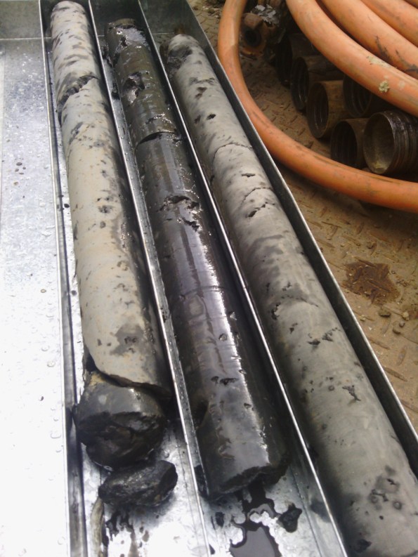
Figure 4 Photo of Trial Column Cores
Risks
The greatest risks with this method are as follows:
- Not achieving required depth.
- Not achieving column depth.
- Incorrect drill location resulting in insufficient overlap between columns.
- Damage to near-by structures and uplift due to the high pressure and flow rate.
To mitigate these risks, the jet grouters rely heavily on computer control and monitoring. The operators are given design parameters from the engineers and they ensure the equipment is calibrated and they adhere to these parameters; they provide a drilling record for every column as part of the QA process. They also drill approximately 100mm above and below the target depths to ensure there is a consistent band at the required depth. They also use GPS and surveyors to locate the boreholes pre drilling and provide an as built post drilling record. If a column is installed in the incorrect location or depth, the process can be repeated in the correct location as the pressure is sufficient to erode the soil-cement mix.
Method Statement and photographs
I have included below a simplified method statement to demonstrate the how the jet grout plug is installed prior to the core raft, as well as numerous photos so you can see how the actual construction process looks. In practice, it took a lot of co-ordination on site as the site set-up and trenches to remove the fluid spoil were a considerable laydown. Interestingly though, one thing I couldn’t capture well on photo was how much the ground bubbled due to the sub-surface pressures created by the process.


Flow Net

Flow Net Take 2
The drawings become a reality!
We are finally building! After weeks of delays waiting for the demolition contractors to handover the basement area and only have sketches of what will be built to look at, we finally got hold of area 1.1 (number 1 of 21 areas) where we will be constructing a 1.25m raft slab. This area in particular has a lot going on; temporary and permanent drainage, a tower crane, two sumps and several columns.
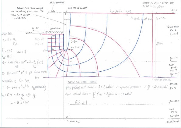
The initial task once handover hand been completed was to waterproof the area of the pour. This involved laying ‘egg crate’ (drainage membrane) on the ground where it will act to diffuse pore pressure and stop any water that enters underneath the slab from building up enough head to affect the slab. The waterproof system that is being used is SIKA. From what i can see this system seems to be a licence to print money. SIKA will only provide their 15 year warranty after one of there representatives has inspected it, and will only sign it off if their products have been used.
 This ‘egg crate’ will be laid across the entire site.
Once the egg crate had been installed, a 50mm layer of blinding was placed on top before the steel fixers moved in. Unfortunately one of my duties at the moment is ordering and managing all rebar for the basement. After initially laughing off suggestions that this was one of the harder/stressful things for an engineer to manage ( I believe I said “how hard can it be?”) it has become the absolute bane of my life. After 6 deliveries there has been something wrong with almost every one; late, wrong or has bits missing. This would not be so bad if the site has stock rebar lying around, however the QS department will not allow such a thing and we are only allowed to have the exact bars that we need on site. This means that when a bundle of 50 bars is left in the yard in Wales and doesn’t make it to London it becomes a major issue. The construction manager does not want to hear the word ‘delay’ at any time!
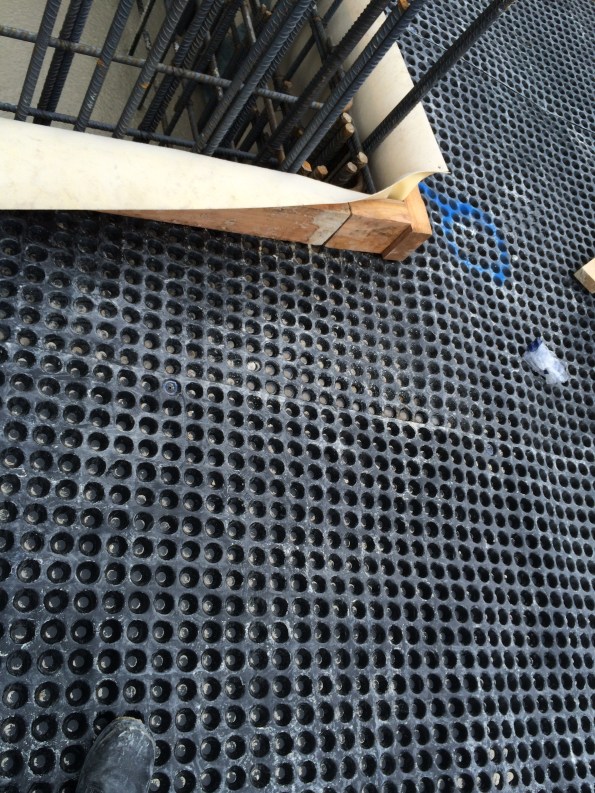
When the correct rebar is on site the steel fixers throw it in very quickly. This pour alone had just over 35 tonnes of rebar.
Bottom mat being installed alongside one of the sumps.
Further work on top and bottom mat. Drainage being installed on the foreground, crane base can be seen in the background.
The crane base was particularly tricky to install. Four concrete plinths had to be cast into the bottom mat and the base lifted into position on top of them. There is a 0mm tolerance between the four legs. Therefore this required a lengthy exercise of adding/removing steel shims from underneath the legs and tightening the leveling screws. This is much easier said than done and it took a few hours before there was a 0mm difference between all four legs.
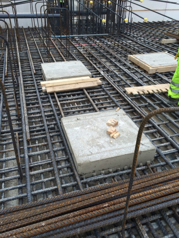
Plinths ready for a crane.
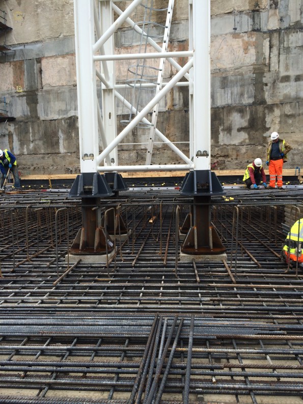
crane base in position.
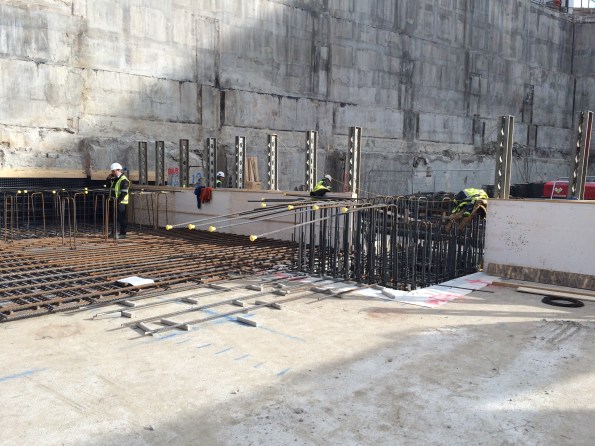
After 6 days of of steel fixing, carpentry, welding and lots of other things the area was ready for concrete. 320m³ was poured in one very hectic day, it took around 12 hours to get it finished and this is not the biggest pour on this project by a long shot. At peak periods we will be pouring around 3 slabs a week.
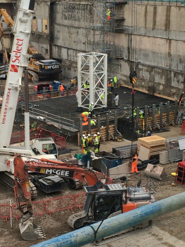
The area ready for some concrete
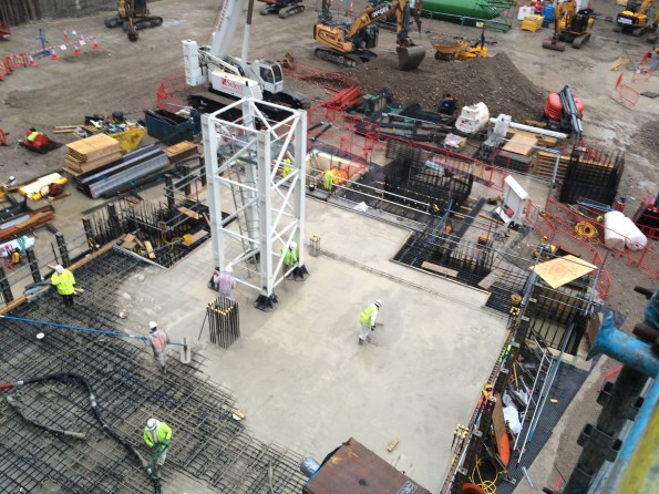
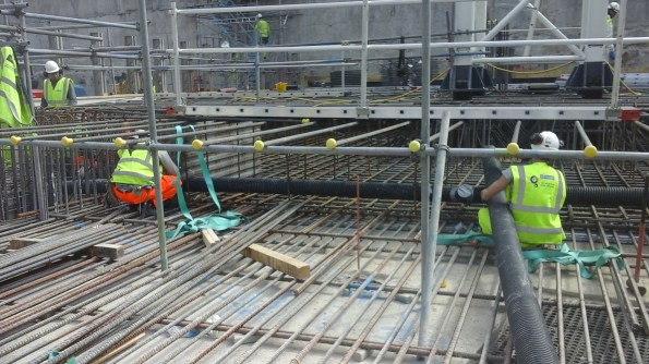
About 10hrs into the pour.

the pour would need to be power-floated. Note the large puddles forming due to the torrential rain that came down all day. The gaps between the crane base and the concrete will be grouted at a later date.
A busy few weeks on site and only set to get busier. The main issues encountered so far have been:
- Stores – Expanded operate by using a ‘just in time’delivery philosophy. The materials they need will turn up at the right time in the right place, therefore removing the need for large stock piles of equipment on site. In theory this is a good way to go about it, however, in practice there are many times when the right stores do not turn up or are sent to the wrong place thus creating a threat to the project timeline.
- Logistics – the site is very restricted and has a complex logistics system that goes with it. The gatesmen will turn away a vehicle if it is not on their list so all deliveries have to be booked in a week in advance. Again, this does not work well in practice as there are always last minute deliveries and changes to the schedules. I have had to sweet talk them on more then one occasion to get them to let a last minute delivery in.
- Overzealous construction manager – not really that much of an issue, more a minor bugbear. The is a very specific schedule with pours taking place simultaneously and lots of moving parts. One of those moving parts is the construction manager. He has been a coiled spring waiting to start work and now that we have it is hard to reign him in. Everything must be done NOW, regardless of whether there is the stores or manpower with which to do so. He has been nicknamed the Tasmanian Devil as he sweeps through the area and causes havoc and confusion but somehow manages to get the job done.
On a separate note, today I brought another cat. I am one step closer to becoming a crazy cat person.
R&D Build Project

Figure 1 – The design for the R&D Building
Having now been on site for the grand total of two weeks, I thought it was time to post my first blog and explain the project to set the scene for future blogs.
PROJECT OUTLINE
The project I am working on is the construction of a 56,000m2 Research and Development (R&D) facility North of London. The build covers two sites, with a main R&D building to the North and an Energy Centre to the South with a public road dissecting the two sites. A 4m wide, 150m long, services tunnel runs under this road, connecting the R&D building to the Energy Centre to provide mechanical and electrical services and data. The road running through the site is an important ‘blue lights’ route for the emergency services and the South Site has a high speed railway running along its Western boundary – both of which create significant environmental challenges and places a number of constraints on the Project. Skanska Construction UK Ltd are the Principle Contractors for the Project.

Figure 2 – The Energy Centre
PROPOSED DESIGN
The R&D Building is a 4 storey reinforced-concrete building comprising a basement level and ground level accommodation, consisting of six glass boxes, supporting a two-floor disc. The disc contains two floor plates and has a staggered vertical façade and saw-tooth roof. Upon the roof there are six small external open plant rooms. The R&D building is still in the construction phase with the majority of the basement concrete pads still to be constructed although work has started on the ground floor with some of the Eastern concrete floor pads being poured.


Figure 3 – Construction of the R&D Building
The Energy Centre is a 3 storey steel frame building traditionally built and enclosed in cladding of different types. It has a lower basement area to only one part of the building and one side of the building is allocated to Facility Management and so includes a number of offices and control rooms. The building has a flat roof which will be used to house some mechanical plant including cooling towers and AHUs. Two large flues will run from the roof to the basement to provide an exhaust for the Cooling Towers, boilers, generators and combined heat and power (CHP) unit. The steel frame for the Energy Centre is still under construction. The tunnel connecting the R&D building to the Energy centre ‘broke through’ last week and so work is underway reinforcing and completing the tunnel walls.

Figure 4 – Construction of the Energy Centre
CONTRACTURAL ARRANGEMENTS
Due to the well-developed relationship between the Client and the Principal Contractor (Skanska UK), the project is being conducted under a cost plus JCT contract with the client retaining the design and ground risk. I am working for Skanska Rashleigh Weatherfoil (SRW) who are the Building Services arm of Skanska Construction UK Ltd. This means that Skanska UK sub-contracts the building services installation to SRW who in turn manage the building services projects and then contract the installation work out to sub-sub-contracts. The various mechanical and electrical supply and installation packages are conducted under fixed lump sum contracts.

Figure 5 – The services tunnel linking the Energy Centre to the main R&D Building
SO FAR SO GOOD……
As a project manager in the MEP (Mechanical, Electrical and Plumbing) Team for the Energy Centre, I will be involved in both the electrical and mechanical fit out of the Energy Centre and services tunnel which is due to start in Aug 16. Currently I am managing a package to plan, tender and contract out the off-loading, moving and placing of the various plant (boilers, generators, transformers, chillers, large pumpsets, CHP etc) and so I am getting plenty of exposure to the tendering and procurement process. This is proving to be a valuable first role as it means studying all of the technical drawings and developing an understanding of the wider M&E packages – all of which this package will support.
This project is very innovative and is utilising several interesting design features such as a 270m deep ground source heat pumps, a new revolutionary, highly-efficient, baffled cylindrical heating shunts (first time this technology has been used in the UK) and stainless steel rebar to name but a few; and so I already have a few TMR titles in the making!
Gary Jackson
Public enemy #1
The Calder Highways Overtaking Lanes (CHOTLs) project is to construct 2 overtaking lanes on a stretch of very straight, sleep-inducing, 2 lane – 2 way road some 550kms from Melbourne in rural Victoria.
As Design Manager for the CHOTLs, I held a kick-off meeting with the Client (a local highways authority) to nail down what was in my scope of works and what was out. I then drove the 6 hours to the proposed locations to do a site walkover (lessons learned from the Amaroo project).
I am to deliver a detailed design to the Client by the end of June. Drainage and pavement structural design are not included in the scope of works. The OTLs are to tie into and match the existing pavement structure with subsurface drainage excluded from design. Essentially, I am delivering the geometric design.
So, Q1; “what is the enemy doing and why”? Remembering the triple bottom line (people, profit and planet), my enemy is the planet, and it does what mother nature says it must.
The stretch of road where the OTLs will be constructed is extremely environmentally sensitive. Buloke trees and the mallee emu wren make planning construction in this area a challenge and has already resulted in a re-visit to site to seek alternative OTL locations.


Traditionally it was accepted that if you veered off a highway at 110km/h and hit a tree within 9m, you could be fatally injured. The solution was to remove any trees within 9m of the road verge. Increasingly stringent environmental legislation has made it illegal to remove certain trees. The environmentally friendly solution is to install Wire Rope Safety Barriers (WRSBs) in the pavement verge.
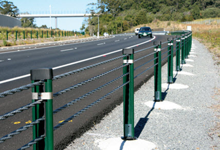
Wire Rope Safety Barrier (WRSB)
So that’s the trees, the birds and drivers looked after. The benefits of the WRSB seem flawless, unless you are a kangaroo. Kangaroos are stupid and routinely get cleaned up by trucks and cars. The issue with installing WRSB is that if a Kangaroo is to jump into the road, they are not as likely to jump out of it when WRSBs are installed. Areas with the WRSBs have seen an increase in the number of collisions between vehicles and kangaroos. You’d be forgiven for thinking that kangaroos are a dime a dozen and therefore expendable. The problem is that they grow to 6ft and hitting one with your car will write off the kangaroo, the car, the WRSB, and potentially yourself.

Public enemy #1
In my opinion, it would seem that the order of importance is planet, followed by people and then maybe profit. There is no 100% solution to designing out the risk of nature and man crossing paths, but ensuring the sustainability of protected trees and birds is a higher priority than looking after the kangaroos. It’s no wonder most trucks and utes have bull bars.

Kangaroo defence
Battersea Power Station and NLE Update
Battersea Power Station
In the last few days I managed to get on a visit to the actual Battersea Power Station (part of phase 2 within the wider Battersea project) after I hosted some of the Phase 2 engineers around the NLE site. I took some pictures and thought they might be interesting.
The Power Station itself will become home to a whole myriad of things, from multi million pound apartments, roof top gardens, a hotel, cinema, restaurants, office space and event space.
I floated the idea of a fly through drone video sequence of our site to the Project Manager but he didn’t seem to interested.


NLE Update
Project milestone achieved, on the completion of diaphragm wall piling within the Crossover Box. Other than the release of funds to have a beer or two on the project it means that we can hand over some space and start the excavation. We dont the whole box as rotary bored piles still have 4 weeks left to finish so we are chasing them out of the box as we continue to excavate.
Having excavated from 101m ATD to 97m ATD the diaphragm wall need breaking out to expose the starter bars. Maximum effort to break concrete as quickly as possible without bending any bars. We are quite content with the lack of bent bars so far.


The sheet piles have started springing a few leaks. They did not have any bitumen in the clutches before they were driven. We now have a problem to either construct a small sump into the blinding layer at 97m ATD or try and seal them (very difficult to do). So far we think welding might be an option but will then require digging back out to break the weld before the piles are pulled out. Not a massive issue, but interested if anyone knows how to plug a dam? water level is at 100m ATD so no more than 3m of head.
