Archive
NLE Project Introduction

I started on Monday this week on the Northern Line Extension (NLE) at the Battersea Site. The project is a JV between Laing O’Rourke and Ferrovial Agroman known as (FLo).
The project client is London Underground (LU) tho
ugh the extension and stations are heavily integrated into the whole regeneration of the area. So Battersea Development (who are part funding the NLE along with 41 other developers) are leaning quite heavily on London Underground. Phase 3 of the Battersea development will sits on top of the station box. A big change to the structure caused a change to the design of the station which has resulted in an 8 month delay, and the design for the station is still being finished. Regardless, the political pressure (Boris Johnson’s office) would still like the development to be finished for 2020. I believe the commercial teams are still debating who will pay for this. The change to the structure caused the design to be changed delaying and extending the project length.
The Project
The project is a 3.5km extension of the Northern Line which will continue the Northern Line from Kennington with two new Stations at Battersea and Nine Elms. The line will have 100m overrun tunnel (under the cats and dogs home) which will serve to store two trains over night for morning service. That tunnel will eventually connect the line to Clapham Junction. The value of digging just 3.5km with two TBMs is apparently justified. Clapham extension too can’t be done now as there are no funds and apparently Clapham junction cant take the additional capacity just yet.
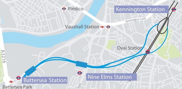
In outline, the project is split into four sites. Two stations at Battersea and Nine Elms and two shafts at Kennington. The box at Battersea will consist of the station box and a crossover box. The crossover box (space for trains to swap sides before they return) will be used as the launch tunnel for two TBMs (Tunnel Boring Machines). The station at Nine Elms is relatively independent other than they must be at depth before the TBMs arrive. The last two sites are the shaft that connect to the existing line at the Kennington Loop where the TMBs will be lifted out. The shafts will then remain as ventilation and emergency escape for the tunnels.
Joint Venture.
I understand that Ferrovial were brought onboard primarily for their tunnelling experience where as Laing are taking the lead on the station boxes and the shafts. Despite this the site office is a 50/50 mix from both companies. I understand there is a slight friction with the Spanish side of the team as they are very commercially savvy but see the role of a site/section engineer in a very different way. Commercially sensitive material is apparently spoken in Spanish which makes by ability to speak the lingo quite helpful.
Design management and leadership
Sorry Mike. No pictures.
You are sure to have heard this phrase before: ‘Sandhurst is the best leadership academy in the world’. I have always had mixed feelings about all that and whether we as the military are as good as the rhetoric, but maybe I’m wrong. I’m not sure if others have had similar experiences in the industry. There were plenty of ‘tense meetings’ in construction, though I can imagine more shouting goes on away from the client; I didn’t really expect it in design though.
I’m not sure if there is any more background to him but the project manager on the Ft Drum NCOA is apparently a known bully. This week’s conference call a shouting match ensued between him and the generally mild mannered design manager. It certainly wasn’t my place to jump in and so I joined my colleagues in gently turning down the phone volume and letting the storm pass. Why? The issue was about a design freeze that had been issued by the project manager due to a VE modification (cutting a 12” slice out of the centre of the building, which clearly has architectural and structural implications). The project manager was arguing that although drawings couldn’t be updated there was still other work that could be done.
So what? The issue with the management of the project in my opinion comes down to two things: communication and the long handled screwdriver:
- On the communication front the project is terribly managed. Meeting minutes are only produced because the Fire Protection Engineer and I produce them as a de facto rather than de jure Other information is continually asked about despite there being a well set up folder structure for IM. Finally, and most relevant in this case, no one had actually told my office that we were to stop modeling; which I pretty much spent the whole of last week doing!
- As for the long handled screwdriver, the project manager is stepping on the design manager’s toes. He has been directing some of the designers and clearly keeping the design manager out of the loop; linking back to communication. Also, and it may just be a bugbear of mine but he uses the word ‘I’ too much as if all the decisions are his; which clearly they are not as he is neither the designer nor the client, rather a conduit for information.
Coming back to the shouting match what really surprised me, and the other Baltimore designers, was that they were arguing in front of us. Whether there are issues in the background or not this does not appear to be the basis of good team building.
Design Process
Design process
Background
The method of getting sewerage from the current outfall point in the Thames into the new Thames Tideway sewer is via a series of chambers and a 30m shaft. At the Putney site these chambers are located on a foreshore site. To facilitate the construction a cofferdam is required.
This blog looks at the approach taken to decide how to size up some piles for design development.

Putney Embankment Foreshore – End state river wall is the rectangular box in the foreground.
Durability
Tideway (the client) require a 120 year design life for all structures. This is onerous but after Guz’s recent blog on his river travels I can see why there is pressure to prove everything meets the design life.
Tender stage
Tender documents had the permanent cofferdam as a secant wall. To enable construction an outer vast temporary sheet piled cofferdam was proposed.
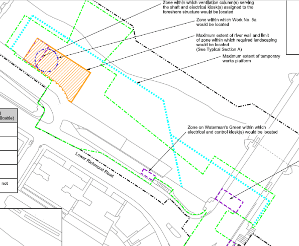
The blue dotted line is the extent of the tender document sheet pile wall. The orange box is the proposed site location.
The contractor’s tender submission was an optimised design by combining cofferdams to have a single thicker sheet piled solution which would satisfy temporary and permanent conditions.
Contractor’s tender submission – Sheet pile wall to act as a temporary and permanent wall.
The issue
Proving a sheet pile will last for 120 years is a bit tricky. The River Thames is fresh (ish) water but the fact sewerage is being discharged nearby creates a risk of microbial induced corrosion which erodes steel and makes arguing the case that all will be fine (as in only 1 or 2mm rather than 5 or 6mm difficult). Unfortunately the UK national annex is more onerous than the main eurocode, I.e. assumes more corrosion occurs.
Plan B
The contractor is keen to use a cofferdam which works in both temporary and permanent cases so have asked the Arup-Atkins joint venture to look at tubular piled options. Steel with concrete encased inside. This can be split into 2 cases. 1. Steel is non-sacrificial and last 120 years and 2. It does not.
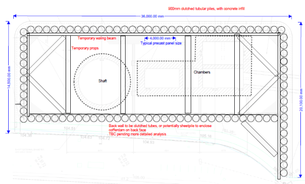
Tubular pile option – outline sketch only
How does the cofferdam get built?
- Modelling the construction sequence for either case is the same:
- Install cofferdam
- Install top prop
- Dewater
- Excavate to formation level
- Install base slab (acts as a bottom prop)
- Wait 2 years while shaft is excavated
- Move to drained conditions.
- Re-fill cofferdam/construct internal chambers to underside of prop level, back to undrained conditions.
- Remove temporary top prop.
- Finish cofferdam/structures, apply surcharge
- Excavate and place scour protection.
- Allow for some worst case tidal and tidal lag.
- Long term case – move to drained conditions.
- Case 1 – steel remains, Case 2 steel does not.
600mm tube option shown below.
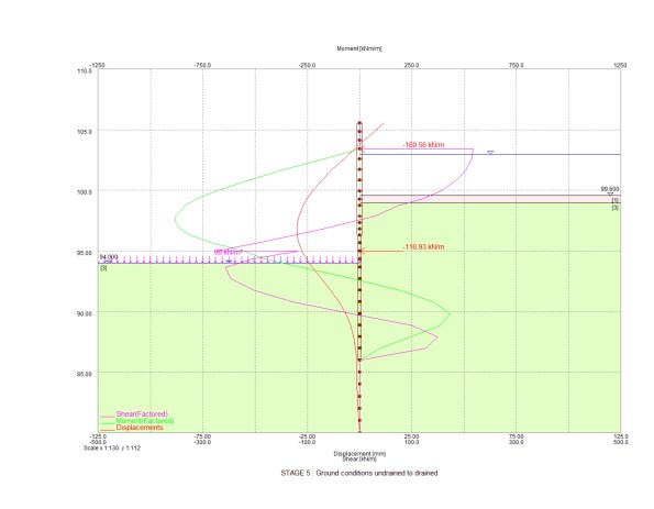
Stage 5-8 in stages above – excavation to full depth with base slab at drained conditions

Final stage with deflection of wall shown in red (105mm) and bending moment in green (1MN)
Stiffness
Understanding shear, bending and deflection throughout the sequence was key. Various pile diameters were tried but this was simply an adjustment of stiffness in the Frew model. EI based on section size, steel and concrete Young’s Modulus. 0.7EI and 0.5EI were used for temporary and permanent concrete strengths. The difference for the 120 year case comes at the final stage where only the section properties of a concrete section above bed level can be taken into account, i.e. a reduction is stiffness. More onerous is the reduction in moment capacity the section has without a steel pile included.
The results
After trying various tubular pile sizes I got to a 600mm pile for both cases above as worst moments were in temporary case (max excavation rather than maximum fill height), so loss of steel section was not an issue as final stage was still below moment capacity.
Unfortunately I made a stupid error in the fill material (somehow I assigned a granular fill a high cohesion value) within the cofferdam which meant I had lower bending moments in the long term than I should have. That was identified before presenting to the contractor so I only lost face internally.
The amended results showed that a 600mm diameter pile works in the non-sacrificial case and a 900mm diameter pile works in the sacrificial case (due to reduced moment capacity).
End state deflections were somewhat high (100mm) but all of the modelling was done at DA1 combination 2 which is not the case at SLS. Also some of the water profiling is a little unrealistic (high level inside the cofferdam, very low tide outside). There is, however, some assumed stress lockins. For example early stages see the wall bend inwards, later stages see it pushed outwards. Difficult to know if this will actually occur so this is a probable case and greater deflections might be expected.
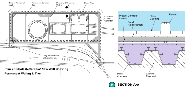
Cladding
The front face of the river wall has stone faced cladding panels which need to be fixed to the piled wall. The connection detail raises questions on durability – casting in stainless steel brackets works but if you touch a stainless steel bracket against a mild steel pile you get greater corrosion so some thought is needed to avoid that. Additionally, final deflections up to 100mm although equate to a small angle mean the top of the cladding is off-set further in order to backfill between the cladding panels and wall. This means the cladding load acts at a greater distance causing more deflection. It also makes it harder to pour something in between the piles and the cladding panels.
Design meeting
After a week of looking at all the options the proposed solution from Arup-Atkins (us) was the 600mm pile thick enough to corrode and be acceptable in the long term. I.e. a section size that was acceptable in the long term and then a corrosion allowance added. The contractor is now going to price this option. Although more expensive than a sheet pile option, it is cheaper than doing the vast sheet pile cofferdam and there are significant savings in temporary and permanent works (fewer internal props and ties needed because of the stiffer piles).
There was sensible input from the contractor about ease of installing 600mm diameter piles versus 900mm as well as lots of points about presenting a solution which meets the client’s durability concerns.
Outcome
We wait and see what Tideway say – they may reject all options and say build it as per the tender documents. If this is the case then I wonder what the point of early contractor involvement is.
Lessons
The whole issue and reason for having to look at alternative options is because of durability concerns raised by the client. The optimised contractor solution was/is a sensible plan and on a pain/gain contract it is worth trying to make savings.
The best thing I see having gone once around the process is developing multiple options to give the contractor the choice of what to present to the client. This enables a solution to be put forward on technical merit.
The plan to get the tubular pile costed before presenting to the client presents risk (for the contractor) has failed because of how busy the commercial team is right now which might turn out to be an issue.
I have learnt a lot about the importance of how something is to be done without the need to go into detailed calculations – certainly the case at concept design stage.
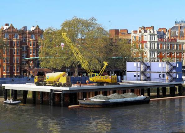
Temporary works jetty solution to build the new site. All by river approach demonstrated with barge removing spoil.
Oz NDY – Return Air Plenum Issues – Part 2
Following a site mtg we have a much clearer understanding of the issue at hand. The mech contractor, Envar, have sent us a mark-up (as requested) of the location and sizes of all holes made by the builder to initially increase air flow; which it has.
So why are we not getting the correct RA flow to the AHU? It also came to light that there is heavy congestion (as shown in fig 1) around a services (namely ducting) choke point (about 1 m2) which is restricting the RA flow. The congestion issue is unique to this level due to the balcony which a severely reduced the overall free area by approx. 1 m2. So, in theory we could turn the closest partition wall into a sieve and we would still have the problem. We can’t practically do this though as there isn’t enough space in this particular partition.
Therefore, we still need to get the balance of air from somewhere which the AHU fan is drawing in. So with the choke point in mind this will have to come from the SA side (the corridor) outside the plantroom. This corridor is open to the large open-plan office area but air flow either end is stopped by pneumatic actuated doors (for security as these areas are sub-tenanted). So what? The makeup air would be mostly SA and not RA as intended. So how does this affect the CO2 levels?
Below I’ve recalculated the area of hole required which would be incorporate as either a door grille in the plantroom door, or, depending on size, it could turn out to be a complete louvered door.
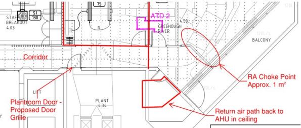
Figure 1. Return Air Choke Point in Plenum.
Calculations
A quick calculation to check the hole size required:
Q = 8.839 m3/s. This is the entire SA flow rate that is trying to get back to the AHU as RA.
A = 1 m2. The approx. area of free flow through the choke point.
Therefore, V = 8.8 m/s. That’s pretty quick and why it has also been reported that a few ceiling titles are flapping around near the exit hole from plenum into plantroom. These are being addressed by replacing with egg crate extract grilles.
If we want to achieve a steady flow rate of 5 m/s then this gives an A = 1.77 m2. Subtract from that the area we do have (1 m2) = 0.77 m2 hole required.
On a basic 2100 x 920mm door (leaving an edge of 100mm both sides) gives a door grille neck dimension requirement of 1100 x 720mm = 0.79 m2. That’s the ‘free air’ area needed where a louver or grille would require being 50 – 60% bigger to take into account the area lost due to the vanes. So, it would need to be 1.26m2, which is about 1800 x 720 = 1.29 m2 which equates to pretty much the entire door when you take into account the structural edges.
So what? It would require attenuation on the plant side of the door to mitigate plant noises transferring back into the corridor, which shouldn’t be heard too much anyway as it is just a corridor and the open-plan office area is actually through a central kitchen/restroom area.
To check this I spoke to our acoustic engineer and used the dB data. The corridor was reading 52 dB, I then added 25 dB for removal of the current door and then subtracted 5 dB for adding a louvered door with some attenuation on the reverse side. This results in 72 dB being heard in the corridor, which is about 22 dB over what it should be (50 dB being the norm). Therefore, this is a problem and exacerbated by the frequency range of the particular plant, which will be a low rumbling (low freq) which louvers still let through.
It would therefore be better to install an ATD above the plantroom door but this idea was discarded due to a large duct run right next to it running down the length of the corridor. This also means that we can’t put any more egg crate extract grilles in as the one currently installed sits no more than 10mm below the ductwork so this too will be restricting the RA.
The only other option I can see is putting in a large or two smaller ATDs through the wall area into the plantroom. But even this has its issues: is there free space on the other side of the wall? How far away is the AHU and can we fit a ATD in? Being the base build, will the building owner approve it?
I have also been informed the AHU has an economy cycle (which I should have expected) where the ambient OA temp dictates how much OA is used rather than wasting energy in cooling RA when there’s ‘free’ cool air available from outside.
ATDs
I made a point of mentioning the need for ATDs in the cut-outs. With the extra holes present no occupants have complained of cross-talk, therefore Envar suggested they would get the builder to tidy-up the holes and leave them at that. Ironically, it seems like any holes made in the partition wall don’t need attenuating due to the ductwork congestion.
Oz NDY – Return Air Plenum Issues
Introduction
Prior to Christmas I was given an interim task to investigate complaints of doors being hard to close with loud whistling noises coming from the plantroom door on level 4. The project is a typical tenancy office fitout with construction complete and the office space occupied by Synergy staff.
I was given an initial steer by the project leader; his view being restricted Return Air (RA) flow to the AHU.
Background
The design of the floor (slab to slab) uses the ceiling void as a large RA plenum. The plantroom, containing the AHU, acts as a large mixing chamber mixing the RA (from the plenum) with the Outside Air (OA), which enters through louvers in the skin of the building. It incorporates a CO2 monitoring system that controls the motorised louvers to alter the amount of OA required to keep CO2 levels within permissible limits.
The main floor space is split up in to a number of offices (various sizes) and larger open plan areas. To reduce the chance of cross-talk between these areas full-height partition walls were constructed. Whilst this met the acoustic requirements it created a subsequent problem; the RA was being severely restricted in its attempt to get back to the AHU.
To resolve this, the design incorporated the use of Air Transfer Ducts (ATDs) installed through the partition wall. ATDs are essentially fitted into a rectangular cut-out in the wall and consists of standard metal ductwork lined with acoustic material. This allows both air flow through it and simultaneously reduces carried sound, as shown in figures 1 and 2.
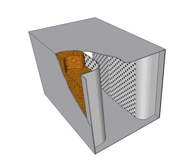
Figure 1. Basic ATD with Acoustic Lining.
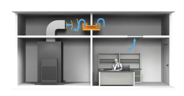
Figure 2. ATD in Use.
Identified Issue
A typical problem found in RA systems, that utilise a plenum rather than a ducted system, is not enough RA finding its way back to the AHU. In this case the number of installed ATDs is insufficient to allow the correct amount of return flow and is creating positive pressure build-up. Effectively, the mixing chamber (entire plantroom) is being starved of its required RA (under negative pressure) and the CO2 monitoring system, not seeing excessive CO2 levels, won’t allow any more OA in. Therefore, the only available air remaining is from outside the plantroom in the corridor (which is under positive pressure) and is now being sucked (willingly) into the plantroom and creating excessive whistling noises. Figure 3 shows a basic sketch I drew to aid in visualising the situation.

Figure 3. Situation Hand Sketch.
What’s possibly exacerbating the issue is the CO2 monitoring system. Because the RA is being restricted the CO2 monitor is most likely reading low CO2 levels, therefore signalling to reduce the OA intake as it’s not required to dilute the RA. This then creates increased negative pressure inside the plantroom and thus makes it easier to pull in air from the corridor due to the AHU fan demand. It then become a vicious circle as this extra air being pulled in from the corridor is most likely to come directly from the SA grilles, with little human traffic, meaning the CO2 levels will low.
Depending on how much the RA is restricted will determine the severity of the symptoms found.
During construction there were a number of design changes, doors being relocated and the like, which caused the air flows to change slightly. This however, is not deemed a significant reason for the symptoms being experienced.
Resolution
The resolution quite simply requires increasing the number of air passages through the full-height walls. As stated this had already been designed for and implemented through the use of 5 No. ATDs, however, clearly more are required. Figure 4 shows the drawing mark-up with existing ATDs (blue) and my proposed design for additional ATDs (pink).
Previous Resolution Attempts
The mech contractor had already attempted to solve the issue by cutting holes in certain locations within the full-height walls. While this may have helped to alleviate the issue, it has not solved it.
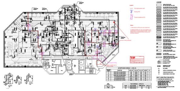
Figure 4. CAD Drawing Mark-up.
Design Calculations
I conducted some basic calculations to determine the number of ATDs required, allowing the same rate of return air flow as that being supplied to the floor space, resulting in a more favourable neutral pressure.
The calculations included splitting the floor space into sections, boundaries based on the full-height partitions, where I then added together the SA from each diffuser in that section. I then worked out the area required (using Q = A x V based on a 5 m/s air velocity) to get that flow rate through the wall to the next section. I continued the same calculations for the other sections, remembering to carry through the flow rate from the previous section as the RA from the entire plenum space is trying to get back to the same point (left to right when viewing the dwg).
In total I calculated an additional 9 No. ATD2’s (600mm x 400mm) were required. In truth it’s only the cut-out dimensions that are actually required to solve the air flow issue, not the ATDs per se.
Design Considerations
There are important factors in positioning ATDs within a plenum: availability of space between the upper floor slab and false ceiling, space between other services, and understanding the use of the rooms either side of the full-height wall to name the most important. All these were considered in my design. The last consideration, the use of rooms, is particularly important as this could determine the possibility of negating the need for ATDs in a particular location altogether. That is not to say there wouldn’t be a cut-out, just no ATD installed, so still allowing the required passage of RA.
COAs
Two COAs were considered, with time, cost and quality in mind. However, before the suggested COA is carried out a number of RFIs must be answered by the mech contractor, these are: confirmation of the location and size of previously made cut-outs, and an estimate on the availability of space to install the ATDs. The location and size of previous cut-outs is important as these could be utilised and potentially increased, based on the calculated sizes above, as suggested in the COAs below.
COA 1
This would be conducted in two stages, both during out of hours so as not to disrupt staff working:
Stage 1 – Make the cut-outs in the full-height partition walls as indicated on the mark-up drawings. This should solve the issue, however may lead to excessive cross-talk. If the room pressures have been restored, the symptoms disappeared and there is no detection of cross-talk, or it is at an acceptable level, then the works will be complete.
Stage 2 – Assess the level of cross-talk, if it is not acceptable then conduct stage 3.
Stage 3 – Install the ATDs in the designated cut-outs, thus solving the cross-talk issue.
Pros and Cons
The main pro is: If stage 1 is sufficient there will be a substantial cost saving on negating the need for possibly all or at least some of the ATDs; each approx $1000 a piece depending on size.
The con is: If stage 2 is required then there would be extra labour costs due to the mech sub-contractors having to go back a second time to install ATDs.
COA 2
Do as COA 1 but all stages in one go.
Pros and Cons
The main pros are: Reduced labour costs for the mech sub-contractor and all the work being done in one go means minimal disruption.
The con is: The ATDs may be superfluous in solving the issue and therefore present an unnecessary cost.
Noise Level Consultation
I discussed the issue with our acoustic engineer and am confident that the overall cheapest option, that still achieves the required acoustic quality levels, is COA 1. This is based on not all the positions identified requiring ATDs. The exact number cannot be confirmed until a further assessment is conducted post stage 1 of COA 1.
Recommended Solution
The recommend solution is COA 1 but I envisage having to discuss these actions with the mech contractor, as alluded to, to get answers to my RFIs. This may also involve going on site to discuss further.
Update
During the preparation of this blog I learnt, through a third party, that the mech contractor indicated it wouldn’t be possible to fit the ATDs as proposed due to lack of space in the partition wall around the plantroom. There were some other suggestions mentioned, such as, installing a large transfer grille in the corridor/plantroom wall but this would need to be quite large to solve the issue and would likely look pretty rubbish not to mention noisy. It would then require an attenuator on the plantroom side to attenuate the plant noise. I think the next step is to meet with the mech contractor to discuss options.
What did I learn?
A key observation, which extends to all projects, has been that no matter who you ask for advice, you will always get a slightly different answer. The key principles will be the same but individual engineers’ will be basing their ideas on their accrued experience. I suppose this highlights the meaning of engineering, derived from the Latin ingenium, meaning ‘cleverness’ and ingeniare, meaning ‘to contrive or devise’, and just goes to show there is more than one way to skin a cat. The challenging part is to learn how and why these little design nuances can aid in delivering a more technically, sustainable and economical solution and therefore aid in refining your design skills. The technical solution also needs to be balanced with any political considerations, especially when wishing to win any future work with the same client.
I also learnt about the disadvantages of plenum based return air systems and found this article helpful in understanding:
In Other News
I organised a surprise birthday present for the wife; a great view of Perth from 1500ft. It included a shot of JHG’s PCH project and the new sports stadium, managing contractor being Brookfield Multiplex (new alternate Ph2 attachment). I’ve also included a few other snaps…
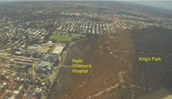
Perth Children’s Hospital.
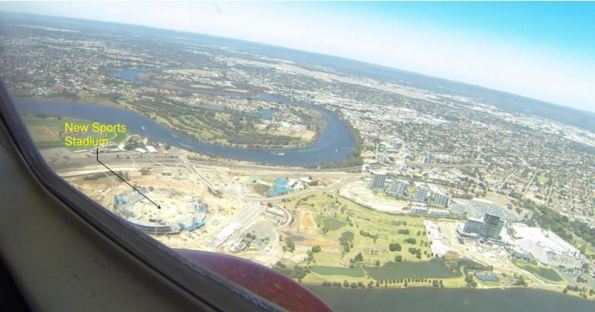
Perth’s New Sports Stadium – Still in the structural build stage.
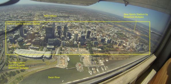
Perth’s Central Business District.
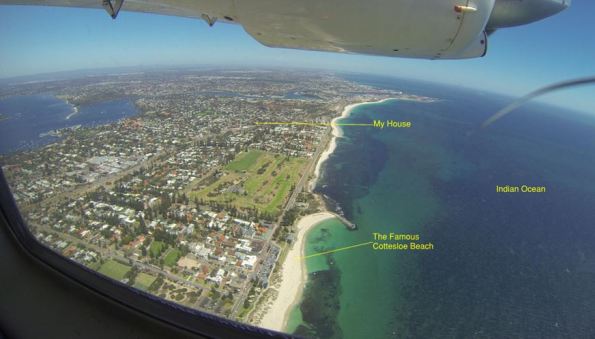
WA Coast Line.
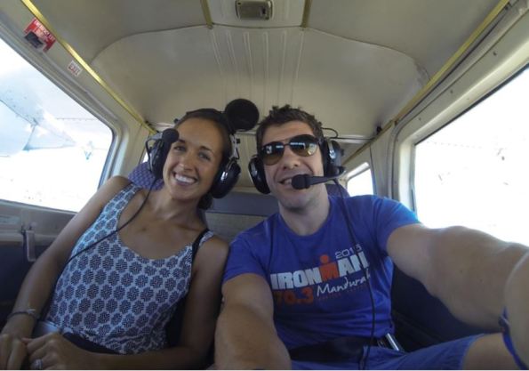
Happy Wife Happy Life!
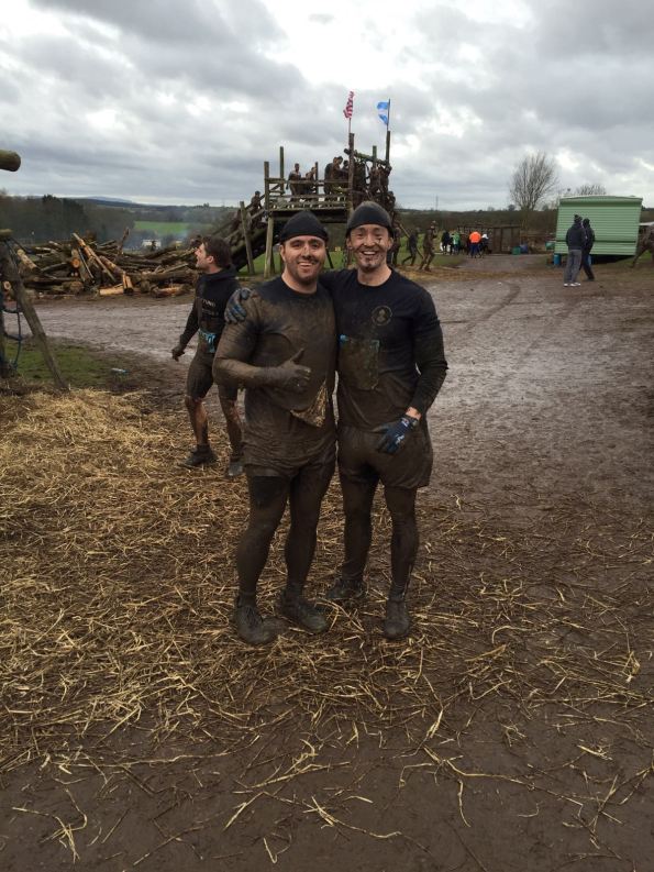
PEW Does Tough Guy
Original article written for Sapper Mag:
On Sun 31 Jan 16 members of the Professional Engineer Training (PET) course embarked on the ultimate test of civilian toughness – Tough Guy 2016. Four elite members of the cohort were selected to compete; Captains Grant, Kiddie, Palmer and Parton had trained for literally hours and were in peak physical and mental condition as they journeyed over to the exotic lands of Wolverhampton for the event.
For those unfamiliar with the Tough Guy Concept the event calls for competitors to cover 15km of cross-country running interlaced with wet and muddy obstacles and hill sprints. The theme for this year was “The Somme” with the course culminating in an obstacle course named the ‘Killing Fields’ with electric fences, burning hay, concrete tunnels, a lot of cold water and endless mud.
 Morale remains high for Kiddie and Grant.
 The ‘Toughened’ PET team celebrate.
Unfazed, the team donned their lycra, neoprene hats and X-Country trainers and fought their way to the front of the 3000+ people starting the race. At the starting cannon the team was immediately split into two groups and ran hard to get to the front of the pack; myself and Capt Parton found ourselves in a group of crazy Germans and Danes who remained with us for the rest of the event. The next 10 miles blended into a haze of throbbing legs, ice-cream headaches and a lot of bruises. Particular highlights of the course include seeing a fellow competitor dislocate his shoulder, a series of twenty 50m hill-sprints (some carrying a car tyre) and an alternating ditch-hurdle arrangement called the ‘Gurkha Grand National’.
Special mention is due to the commitment of Fred ‘the tank’ Kiddie who was running the race as part of his first weekend as a married man, fuelled only by a bottle of Lucozade and propelled by a pair of inadequate flat-soled CrossFit trainers. Also credit is due to the old man of the group, Capt ‘Eton’ Grant, who was competing on his 32nd birthday and only managed to get round as he was following a young lady dressed as a bunny girl (whom he followed from Mile 1).
 The team conquers another obstacle within the ‘Killing Fields’.
Three hours later the last of the PEW cohort had made it through the finish-line. Two of the group had finished in the top 150 runners and the team average time was in the top 25% of the field … not too bad for a group who spend most of the week in a classroom.
Thanks are due to Mid Kent College and 1 RSME Regt for supporting the team and allowing them to make such a good effort. Lastly, for anyone brave enough to take on the Tough Guy challenge next year a few tips; issued builders gloves are a must, neoprene hats are advised and more than two pints the night before should be avoided!
Capt Mark Palmer RE
PIANC Study Day
Yesterday I attended a PIANC workshop at the ICE. PIANC is the International Navigation Association, the body that produces codes for ports and waterways and governs much of what I am doing during Ph3. Coincidently, the chairman of PIANC works for CH2M.
The day focused on the ‘future of design’, challenging and refining codes, and expanding design in to new areas such as seismic (previously not covered).
In parts, the technical aspect when straight over my head as I lacked decades of practical experience however, some of the key takeaways for the day were completely generic across design disciplines.
Some generic points:
Updating of codes – M/515 (Extending the scope of Euro Codes)
There was a public acknowledgement that the updating of ENs due was overly complex, poorly publicised and understood. The main concern were the pending changes (M/515) to load factors, partial and combination factors across all areas of design.
Code Bashing
There is a concern that code writers have become wrapped up in code-bashing. For instance, the ψ (trident for Brad) factor, in ENs is used for long term effects such as creep. So why is that factor appearing, in the same context, in codes dealing with seismic design…surely the impact of the ground accelerating back-and-forth is far worse than a little creep. PIANC are attempting to identify these cases and add clarity/remove confusion within their own codes. They are also offering their finding to the EN and BS committee’s but acknowledge that changing principle codes will not be easy.
The legal requirement of codes
ENs use the would Shall which legally implies you must do it. BSs use Should which implies a recommendation but is supported but an understanding that without just reason or better knowledge it should be considered as shall. The bottom line and advice from PIANC was to treat these as the same ‘a legal requirement’ and only challenge the code if you undertake some form of monitoring, statistical or physical modelling during the design phase.
BIM
Not a single engineer present (over 100 from a wide range of companies) had used BIM for any non-government project. Furthermore, when asked to what degree it had been utilised for Gov projects, only sniggering could be heard. There is no doubt that if used correctly BIM is a fantastic data managing tool that would support the H&S/project files etc. However, this is not happening. The key concern is that as-builts are improving but supporting cals, assumptions, etc are not available which makes future alterations difficult. PIANC is attempting to manage this by introducing the requirement to produce a ‘Facilities Operating Manual’. In essence the factors and design assumptions made at every step of design are to be logged and presented with the drawing pack. This is not optional if designing to their codes. It does not require companies to expose their calcs or software details but an understanding of inputs and outputs along with factors.
Summary
The day highlighted a genuine desire across the industry to refine the policies and the codes in use. The senior PIANC committee were open and seemed active to explore ideas being presented to them rather than trying to justify their latest publications. There was a acceptance that the ENs are so vast that using them as a baseline and working alongside was the most proactive way to progress rather than trying to alter, amend or refine them. The day finished with a short discussion on what, if any, new codes should be written.
Genuinely a good day that expended my understanding of how the codes are born, developed and published. It was warming to see that the industry steers the codes and is not simply constrained by them!
The illusive c’
Does anyone have any recommendations for a sensible c’ for a soft sandy clayey SILT?
I’m thinking I’ll probably assume something around 5, then bash out a quick sensitivity analysis to see how much difference it makes to my foundation design then make a decision based on risk. But I’d be very happy to hear if anyone has experience in this sort of thing? – Damo I’m looking at you, and John obviously!
CCB – Security is A Very Dirty Word
Doing a Guz “two-fer.”
I’ve been working, briefly, on another renovation. An old laboratory built in the 60’s which is now to have some very heavy server equipment put in it. I say briefly because I’ve been kicked off the project by the client, annoyingly.
The request was to assess whether or not the existing floor could facilitate the server equipment loading. A preferred loading arrangement was given, along with the loads of the individual server equipment. The existing floor is a composite slab, 16″ deep steel beams with a 4″ thick slab on top. The slab should be 5″ but destructive testing proves otherwise. The beams are 10″ o.c and span 30′. I calculated that the capacity of the system was around 240kip.ft [325kN.m] and that an increase in capacity would be required due to the loads imposed by the new equipment. I proposed (or at least I would have) a simple framing system which could either a) tie into the existing steel columns, above the existing floor level thereby effectively suspending the equipment above the slab, which wouldn’t see any of the additional load or b) sit on top of the slab tying in structurally – forming (for want of a better phrase) a concrete sandwich between two steel beams. Both have various pros and cons that I could think of, but what I was surprised about was the magnitude of the additional capacity provided by a steel plate which had been welded to the base of the existing composite beam arrangement. It was a lot! It was an accidental discovery made from messing around with simple hand calcs, and an error I made in missing out the base plate initially. Fortunately I recognised that things were off and I went back to check why, otherwise I might never have thought twice about the numbers. The plate itself is welded to the bottom of the existing steel beam and is .5″ (12mm) deep by 8″ (203mm). So not insignificant. The reason it increases the capacity so much though is because of the change it makes to the second moment of inertia (I) of the whole composite section. The original composite section minus the plate has I of c. 975inch^4. The composite section plus the plate has I of c.1985inc^4. When you apply this to the MIFY equation you can no doubt see the gain in moment capacity; The I has pretty much doubled for a very minor change in y. This could be a neat trick to remember if additional capacity is required but other methods of engineering (say replacing beams, or installing propping) are not viable.
Anyway, like I say I’ve been kicked off the project for being Australian. This was discovered when I called the client to ask for specifics about the server equipment; exact weights, how the loads are transmitted to the ground, sizes etc. Clearly alarmed as to why there was an “Alien” poking about he fobbed me off to somebody else, who wouldn’t pick up his phone and presumably called USACE. Turns out its a classified project. Shouldn’t be a problem thinks my line manager, who knew this. Well it is.
Alan. I’ve said it before, you are entering a foreign country. Brace yourself.
And also:
Since hearing that local Dunkin Do’nuts is closing me and Henry have been doing our bit to increase their take.
CCB – 8607 Renovation
Work has been distinctly ‘bitty’ so far with the proposed work on the Fort Lee Training facility still being just that. A proposal. This is mainly down to IT issues which have now been sorted, thanks to a bit of a whinge to my line manager. To fill the void I have been working on the other renovation project I mentioned in my last post.
ATFP / Progressive Collapse
The output required is the technical specification and tender documentation, which is being produced by a number of different USACE departments (electrical, mechanical, architectural, structural etc) with support from the costing department and PM section. The structure in question is being transformed from an old barrack block into office and administrative space. The main considerations for the structural section have been to do with the anti terrorist force protection and progressive collapse system. The ATFP considerations are required because the costs of the renovation are more than 50% of the total value of the building, which is one of several potential ‘triggers’ in the Unified Facilities Criteria (UFC) documentation. UFC is suite of standardised Department of Defense building codes applicable to all branches of the military. There is currently no progressive collapse or ATFP installed because the construction of the original structure pre-dates the current requirements. The ATFP requirements are classed as minimal, limited to such things as stand off and observation requirements. These are fairly cheap and easy to achieve and can be designed in early provided the designer is given enough real estate to play with. In this case this not a problem and as long as the car park is sufficiently far enough away and no trees get planted with branches lower than 5’ all should be ok. The progressive collapse requirements, triggered by the fact that the structure is three storeys and will be a ‘primary gathering area,’ are more onerous. The UFCs say that for this category of building either Tie Force measures or Alternative Path design is acceptable. This renovation is part of an ongoing programme and both methods have previously been used in similar buildings. The preference is to use a tie force method which will see a large steel beam placed in the roof of the building supporting hanging steel rods in tension at the column locations. These tie into each floor slab, supporting it in the event of column removal. When I say ‘preference’ I mean this is the USACE preference, not necessarily the client’s (the client doesn’t really care how the building is made compliant with the UFCs, just that it is). This is likely because its been used before and is simpler practically than a retrofit alternative path solution. To this end the UFC requirements have been quoted, but only examples of tie force have been provided. But why not just state outright that tie force is preferred? The technical spec seems somewhat to be leading the eventual tenders to arrive at a pre-determined conclusion but is still allowing some room for design innovation. One of the things required for the project, which will not form part of the invite to tender documents is a cost estimate. This allows USACE to get a feel for what the incoming tenders could / should be. I provided a list of quantities of materials I expect will be required for the ‘preferred’ progressive collapse system to the costing team who will build the cost estimate. USACE policy dictates that if incoming tenders are within 10% of the government estimate there is no requirement to go through a negotiation phase to consolidate the difference. So in leading the designers to use the same system then perhaps the cost estimates will be in the same region, potentially speeding up the tender process. Time is, from what I have seen so far, the predominant driving factor on most USACE projects. In allowing some discretion however some cost savings may be realised.
Existing Capacities
The client’s brief will contain a list of requirements to turn the accommodation building into the required administrative and office space. From looking in the UFC I anticipate that this will involve interpreting the requirements and allocating enough space for conference rooms, partitions, storage and general office space. All of these have minimum loading, much like you can find in EN1991. The designer will presumably be trying to find a combination of the above space to meet the client requirements whilst trying to do as little structurally as possible. To help both us and the designer understand how much, if any, work will be involved I’ve provided an annex to the documentation highlighting the existing capacities of the floors.
These are formed from cast in place concrete T sections; 5” beams supporting a 2.5” thick 26” on centre one way slab spanning 24’. The beams have 2 #5 rebar top and bottom (#5 being 5/8” dia.) and the slab has a mesh of undetermined diameter, therefore assumed not to exist. Destructive testing was carried out at numerous locations and most of the above has been confirmed, except mesh was only observed in a few locations. I calculate* that the existing system has a capacity in the region of 17 kip. ft [23kN.m] moment capacity (positive moment) and 16 kip.ft [21kN.m] negative moment capacity and about 4.5 kips [20kN] shear capacity. Using a computer system called Enercalc structural library (if anyones heard of that?) I applied various loading conditions and assess that the designer can do almost nothing without the requirement to increase the capacity of the existing structure. Why is this important, and what have I learned? Its important to know as a client how much you expect your requests to cost. Like taking your car to the garage, you’re much less likely to get ripped off if you know what the likely costs of replacing your brake pads will be. You can either research this yourself or get someone else to do the research, perhaps because you don’t know what a ‘brake pads’ is. In this case USACE is doing the research on behalf of the client so the government department requesting the work won’t get ripped off and can appropriate enough funds from senate to do the work. I learned that clients can be a nuisance. They have yet to identify an end user, but have a few in mind. One of these few has requirements for Sensitive Compartmentalised Information Facility space which sent the electrical and mechanical team into a tizzy. I learned that technical specs and tender documents can provide more than just a bus route for Steve if they are considered properly. They can also do more by saying less in a good way as much as a bad way. I also learned that youtube has lots of really boring videos.
In other news
The snow has gone and I paid $550 to Nissan to fix something on my car. I don’t know what it was called but the flashing light on my dashboard has stopped flashing.
* using a mixture of class notes, text books and a helpful youtube video.
