Archive
Messing about on boats
“Believe me, my young friend, there is nothing – absolutely nothing – half so much worth doing as simply messing about in boats.”
― Kenneth Grahame, The Wind in the Willows
![IMG_0028[1]](https://pewpetblog.com/wp-content/uploads/2016/02/img_00281.jpg?w=301&h=401)
My other day out of the office was prompted by a letter from the Environment Agency to FirstPort property services stating that the concrete defences along the river Thames were damaged and needed repairing.
FirstPort did not know it was their responsibility to look after the defences. It turns out they got the management contract for the development from Berkley homes who built it. This particular detail was in the documentation but no one at FirstPort noticed it. So it was a shock to them when they received the letter in the first place.
The quayside in question is on the site of Brunswick PowerStation (think Battersea cut in half lengthways). The quayside was built in 1948 and therefore designed to the DSIR code. I was chatting to John about this yesterday and the code is so old it even pre-dates him! The code didn’t really take environmental factors into consideration and so the concrete cover to the steel is as low as 35mm. EC2 would say it must be a minimum of 65mm. Additionally these large public projects in the post-war years were a good way of employing soldiers returning home after the war to a weak economy and high unemployment. So soldiers would be given jobs on construction sites, this one included. Their workmanship was a bit dodgy as was the compaction methods of the time meaning the concrete is not as dense as you would expect from modern methods.


The combination of little cover, poor compaction and an aggressive environment has resulted in some fairly substantial corrosion to the steel. Chlorides in the environment penetrate the concrete and the steel corrodes. The corroded steel has a high volume than the original steel and therefore cracks the concrete. Which lets in more water and the corrosion starts again. It’s a vicious cycle.


So we hired a boat and a concrete cover meter and went and had a look.
It is repairable. The problem is that it’s going to be an ongoing maintenance burden which will ultimately be paid for by the residents through their maintenance fees. The bill for this will be over £100k, which split over all the properties in the development is not a huge amount of money, but if they have to do significant repairs each year – which they might – the residents are going to get pretty tired of it pretty quickly.
I’ve got to go to a residents meeting there in a couple of weeks to explain this to them all. Not looking forward to that!
Trusting N values = RISK^100
I’m back!
After some weird issues regarding my account, I can now post blogs again albeit I’ve had to get a new account linked to my work email in order to do so. So when I’m finished at WYG we’ll have to try and set up another account on my personal email so I can continue to see the blog – one for Jim to ponder…
Anyway, about three weeks ago I managed to get out of the office for two days. One day I spent on the Thames on a boat – more on that later. The other day I spent in a field.
I’m designing a couple of crossings over high pressure gas pipelines to provide access for vehicles into a quarry. You may have seen my previous blog where I was tearing my hair out over the vehicle loading. A number of site investigations had been completed previously but had focussed on the agricultural or quarrying value of the site. None had collected any geotechnical properties and I need them to complete the design. So I organised a local Geotechnical engineer to go along and do some boreholes.
I got there to find two blokes (the rig operators) stood by the side of their vehicle, looking at the farm land which is the site, shaking their heads. I said hello and they said “We’re not going on there”. Good start. It was a bit wet, I accept that, but what was he expecting?! The engineer turned up shortly after and we walked the site while we waited for the National Grid bloke to turn up. In order to plant a daffodil within 15 meters of a high pressure gas line you need National Grid to send an engineer to observe. I wanted the bore holes as close to the location of the crossings as possible, obviously. The rig operators didn’t want to go onto the field. Their argument was that it was too wet and the rig would sink. I really doubt it would of, but I was never going to win that one, so we came to a compromise. We selected locations for the boreholes that were on the firmer ground at the edge of the field. This meant that the locations were now more than 15 meters away from the gas pipe and therefore the gas man had driven for 3 hours to get to us only to find he now no longer needed to be there. He checked the locations, gave me a piece of paper saying it was all ok and then left, shortly followed by the Geo engineer who let his rig team get on with it.
![IMG_0034[1]](https://pewpetblog.com/wp-content/uploads/2016/02/img_00341.jpg?w=595)
John previously said that once you see a drilling team do their thing you’ll never trust any of their results ever again. I now agree…
Let’s take N values as an example. The book (CIRIA R 143, among others) says that to get an N value from an SPT you hit the stick with a weight and measure the number of strikes to move the stick 300mm (very simplistically). The report also states that poor operator technique can produce disturbances in the soil below the head that then leads to unreliable results, especially in granular materials, the bigger the particle size the bigger the effect. I’m working in gravel. Oh good then!
![IMG_0048[1]](https://pewpetblog.com/wp-content/uploads/2016/02/img_00481.jpg?w=595)
I watched the crew conduct an SPT at around 4.5 meters’ depth. They drove the collar to about the depth they wanted and lowered a weighted tape down the hole to measure the depth. But they didn’t measure the amount of collar sticking up out of the ground and so don’t know the difference. The point with SPT is that the material is undisturbed. If you don’t know the difference in level between the bottom of the collar and the test level, how can you possibly estimate the amount of material that has fallen from the sides of the hole? And this is a particular problem in large particle rounded non-cohesive soils like gravel.
The operators then introduced the rod into the hole and drove it “for a bit”. Not the stated 150mm seating drive. Additionally, BS 1377 states that the seating drive should be limited to 25 blows. I must admit I wasn’t counting, but I’m not confident it was. They then got a stick with some lines on it, held it against the rod and drew chalk lines on the shaft (cue Brad giggling) where the lines were (at about 75mm intervals). They then drove the rod noting how many blows it had taken to reach each line – or there about. The lines weren’t exactly straight but at this stage that was the least of my concerns. The operator then wrote all this down in his book and made a cup of tea while his mate changed the head over.
![IMG_0069[1]](https://i0.wp.com/pewpetblog.com/wp-content/uploads/2016/02/img_00691.jpg?w=294&h=220&ssl=1 "IMG_0069[1]")
![IMG_0072[1]](https://i0.wp.com/pewpetblog.com/wp-content/uploads/2016/02/img_00721.jpg?w=293&h=220&ssl=1 "IMG_0072[1]")
The crew also took samples at various depths including both the gravel and the underlying clay, which they did pretty well from what I understand. They put the coarse-grained stuff in bags and for the cohesive soils the sealed it in wax to keep the water in and treated it pretty carefully.
![IMG_0071[1]](https://pewpetblog.com/wp-content/uploads/2016/02/img_00711.jpg?w=595)
So what?
So I’ve got some N values and I’m awaiting the lab test results. Do I weight the reliability of the lab test results against the N values since the method of collection looks dodgy? No. There are loads of other factors that affect the accuracy of the N value including the stiffness and exact diameter of the rod and the angle of drive, but I didn’t measure them. So who am I to judge? The factor of safety applied to the results is there for a reason and as long as I try to triangulate the properties with the lab results and anything else I can find I’ll crack on and use them. I’ve got nothing else so I need to use something!
Go on then John, I’m braced!
Stay tuned for… “Messing about on boats”
Revit Padawan
This week has been my first real foray into Revit and the force is not strong in this one. Below is the product of 2 days of hard fought CADing; it’s a good job I’m not billed out by the hour! The model is the ductwork and Fan Coil Units (FCUs) in the accommodation element of the NCO Academy. Blue is supply, Orange is return and green is exhaust.


All the duct work is sized using my new friend the ductilator. It certainly makes the tiresome job a lot quicker and easier than calculating them mandraulically! The flex duct connectors at the ends are basically cheating. However, as we have only just exited the 35% gate I’m sure there are plenty of movements to come and these allow elements to be moved independently without Revit dropping its fill. This is especially true as the zoning of the interstitial space has not been worked out yet. As appears to be commonplace we are waiting on structural to finish overdesigning beams before we can get into the important work of cutting holes in them.

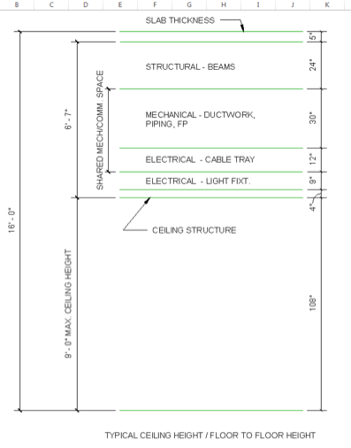
On a more serious note the building was originally conceived, presumably by the architect, as being 18ft floor to floor. Ignoring the training room, and its 12ft ceiling, that will no doubt be the subject of a blog in the future; the remainder of the rooms had a mixture of 9ft and 10ft ceilings. This translated to a 9ft interstitial space in some of the rooms, something which laboratories would be proud of. Arguments about leaving it alone were that the cost of brickwork wasn’t much when weighed against the time, and therefore cost, of trying squeeze everything together. My counterargument was sustainability bringing a big fat tick in the E3 box. I was thinking of the carbon output but to translate it into ‘American’.
To back this up I did some very rough calculations in Carrier HAP (Hevacomp equivalent) which showed that on a summer design day the cooling load would reduce by 2.8% and on a winter design day the heating load would reduce by 7.3%. Sadly, due to the way LEED savings are calculated this doesn’t translate into extra points for design, however it is good for life time running costs.
So the compromise is set to dropping the floor to floor height to 16ft which, across both floors, saves 4ft. The negotiated allowances for each discipline are shown below, though the electrical engineer has agreed to let HVAC enter his cable tray allowance and he’ll work around it; sensible. Everything is conservative at the moment so maybe we will be able to shave a little more off. Although clearly the model is getting ever busier and so unless the height savings are significant I shan’t hold my breath.
In other news I’ve found someone else that uses John’s calculators.

Oz NDY – Shirking Work or Exercising Moral Courage?
Introduction
This wasn’t my intended blog but I wanted to share this now as it only happened yesterday. This blog covers my reactions to being tasked with a piece of sustainability work that I feel is not aligned with my DAP and therefore is likely to fall short of meeting my UK-SPEC requirements. I’m not one to shy away from work but I feel there is sound justification for doing so in this instance.
Background
When I first arrived here I made it a point to explain my raison d’être to both my immediate boss and mentor. I talked through my DAP and expressed examples where I thought I could meet my outstanding UK-SPEC requirements. In particular, E3 – undertake activates in a way that contributes to sustainable development. My take on this, pretty much identical to the bullet points from the UK-SPEC, was to get involved on a new project where I could conduct the stakeholder engagement piece, understand which star rating (on the Green Star spectrum) they wanted to aim for, and be creative and imaginative in coming up with design solutions. Well it hasn’t quite panned out that way…yet.
Issue
The week prior to my immediate boss arriving back in office from extended holidays (cue identified miscommunication) I was given the heads up that there was some sustainability work I could help out with. This seemed to be well timed as one of the sustainability team was about to depart on maternity leave.
On conducting the initial sustainability meeting/training to understand the project and my involvement it became very apparent that what was actually being asked of me was nothing more than an admin and certificate gathering task.
The project
The project, Capital Square, is a new development on the edge of the Perth CBD and the developer has a major tenant, Woodside (in the mining, oil and gas industry) ready to move-in once complete. They were promised all kinds of sustainable initiatives in their current tenancy but the building owner hasn’t come through on any of them. So, they are eager to move into Capital Square and have expressed their need for all the bells and whistles. In Green Star rating terms this translates to a 6 Star building which requires 75 of 100 pts to be awarded the World Leadership title (there isn’t any higher rating at present).
Issue continued…
This all sounded great until I was told that all the Environmentally Sustainable Design had been done and the big push now was to compile all the relevant information (certificates and documents) that provides the evidence of the building actually meeting the points they aspired to. NDY use their own purpose built template (in excel) in which to track the status of this information. The end state being to submit the collated information pack to the Green Building Council of Australia (GBCA) by the end of Mar 16. A quick estimate means that I would be spending 50% of my remaining time on Phase 3 doing this admin based work; not a very constructive use of my time. I’m not saying that I wouldn’t learn anything from doing this work but I can easily get the majority of what I need from a simple review of the template used for this project, which I now intend to do. However, I don’t see any merit in actually going through what seems like two months of torturous spreadsheet compiling.
What did I do?
Immediately, in the meeting, I asked more probing questions to confirm my view of what I thought was being asked to ensure there wasn’t more to it; there wasn’t. I then explained my particular circumstance which immediately confirmed to me that my requirements were not communicated when my stand-in boss set-up the sustainability work I had asked for. It’s not a massive issue but my view is that it all too easily fell into place and solved a resourcing issue but which neglected to consider my needs. I’m not suggesting for a minute that I’m above doing this type of work, or doing as I’m asked in general, but when you consider that we are actually employed under unique circumstances then something needed to be said.
On reporting this to my actual boss, who happened to arrive back on the day this meeting took place, his view was pretty clear-cut. He said “I thought that was just admin work, like what they give to graduates, you’re not going to get anything out of that”.
His view echoes my main justification. I am better off spending those two months project leading on another tenancy fitout project and putting into practice all that I have learnt from my current project lead role and gaining more experience in competencies A1 and A2; also on my DAP.
What did I learn?
You are the master of your own destiny throughout your attachment. Well I actually knew that already but it has been a good example of reinforcing it. No one is going to drive you to follow your DAP so when situations like this arise you have to stand your ground and speak up; with carefully considered and justified reasons that is.
In other News
With all this talk of snow I thought I’d share Perth’s weather forecast…so what? Yes my A/C at home has been working over time.

Shear and UPL
Shear and UPL
This is not what I am doing but a technical problem has popped up on a site one of the members of my team oversees and I thought it was interesting.
Imagine a secant wall in a rectangular formation with an in situ basement box to be poured inside it – see below.
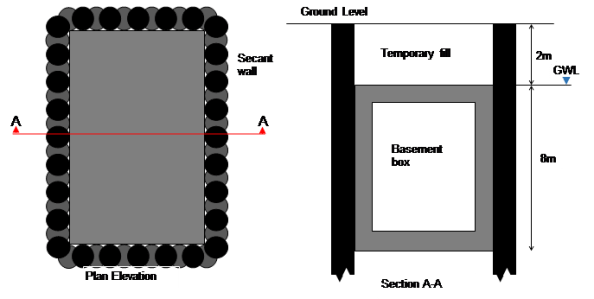
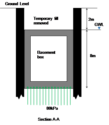
The base of the box is at 10m below ground level and the water level is at 2m below ground level. Over time as water pressures return this creates an uplift stress of 80kpa. Assuming the base and walls have a downward stress of about 60kPa this leaves a remaining 20kPa downwards stress needed. When the fill is placed above the box this results in a net downwards pressure (bulk weight of soil (20kPa multiplied by 2m gives sufficient resistance). However, let us assume that the fill gets removed for a subsequent development (as is planned).
The risk is uplift failure (UPL), I.e. the box tries to move to the surface because of the buoyancy effects.
The solution.
Dowel bars (yellow) between the male secant piles and the internal box provide shear resistance (green arrows) to stop the box lifting up.

Dowel bars fixed between piles (black) and inner box (grey)
The problem
Suppose over time water is able to get between the secant wall and new basement box. Over a bit more time the gap between the secant wall and box might increase a bit more. So the dowel bars now act in tension between the secant wall and hydrostatic head (blue) pushing the box inwards. Over more time still and the dowel bars act in tension due to the lateral force (horizontal green arrows) applied by the hydrostatic head which makes them strain, or elongate, and therefore have a slightly reduced shear capacity.
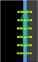
Tension in dowel bars created by hydrostatic head, dowel bars strain (extend).
An 8m depth of water implies 80kPa or 80kN if the dowel bar resists one metre square (for simplicity). E=(F/A)/(ext/original length). Ext/orig=(80/pi d2/4)/E, E (210GPa), d =40mm, implies 0.2mm/600mm multiplied by E (210GPa) equals 70MPa axial stress.
Remembering back to EC3 days or Von Mises, as axial force increases, shear decreases. Therefore this increase in stress in axial force (N) may reduce shear (V) to below the design capacity – Vz Rd reduces as axial force increases.
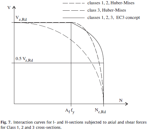
The question is why does the reinforcement bar extend by 0.2mm? The design specified a plain bar, the contractor installed a normal ribbed reinforcement bar into the secant wall which would generate tension between the secant wall and inner box as the hydrostatic head builds. A smooth bar would also lateral movement without reduction in shear capacity.
The problem is worsened when uplift occurs because the rebar it put into bending and therefore undergoes further reduction in capacity. See the 3D graph below where moment reduces capacity even more.

The solution (2)
Install a sleeve over the rebar thus removing the interlock effect of the ribs on the inner wall. This allows lateral movement of the dowel bars to avoid any axial force. Uplift is ten resisted by the dowel bars as planned in the design!
Summary
Clearly there are a number of assumptions and simplifications in this blog (basement box would also resist some lateral force reducing movement, soil type ignored, move to drained approach). I thought this issue was seemingly minor, but with an accumulation of risks (tri-axial forces) the consequences could be high. I would argue the likelihood of the risk arising is low but having specified a design solution to a complex problem, Arup was not going to reverse its view (with full finite element analysis to back up assertions) just to hurry the job along.
Snowmageddon
In case you’ve been living under a rock for the last week you’ve probably heard that the East Coast of the US has had some snow. The fervor of the media attention has been comparable with the chance of a dusting in London. We have had about 2 ft so the panic is perhaps a little more justified. In contrast this is considered normal in places such as the mid-west so why is it an issue for the D.C./Baltimore region.
Like most things I suppose it all comes down to risk as the area doesn’t get snow in these quantities it is not as prepared for the volume as other areas. Looking from a Facilities Management/Design Planning perspective I note a couple of things. We design drainage for 100 year rain events but also should think of the snow equivalent:
- Where to put it. Snow takes up quite a lot of space. You can compress it, but only so far. So what? In our condo there are, or should I say were, some outside parking spaces for visitors. Large grass verges have also been optimized, alongside peoples’ front gardens; any grass area is now a snow store. Also side walks, clearly Americans don’t walk so they are considered fair game.
- How to move it. Shoveling 2ft deep snow out of a driveway manually must be hard work; I can see why people died. Snow blowers are awesome for pathways and you could probably do a short road with determination and planning. Snow ploughs are a given. But the rate limiting step seems to be wheeled loading shovels or skid steer loaders. These have the capability of both heaping the snow higher and of moving it around in a more deliberate fashion than just pushing it to the end of a run. In the middle of the city dump trucks have been used to transport snow out of the narrow residential streets.
- Don’t wait for the end. 2ft of snow is difficult to manage, far easier is 1ft of snow twice. This keeps essential lines of communication open, gets everything open quicker and means that smaller equipment isn’t overwhelmed, therefore a broader range of equipment is useful.
- Drainage plans; three things on this.
- Firstly, knowing where the drains are so that they can be cleared to allow the snow melt in, by either marking them with wands, having a site plan of them or both.
- Secondly, putting drains, close to but not in the middle of the forecast snow collection areas. Close to so that there is not a long stream of water to freeze overnight, but not underneath so water can actually get down the drains. This hasn’t been done so well where I live.
- Finally, and another one that isn’t so great in our condo, is making sure there is actually a fall to a drain. I’ll leave that one as it is.
- Finally communication seems to be pretty key. I could talk about American authoritarianism but I would be descending down a slippery slope towards ranting there.
Obviously the whole experience has been harrowing being locked in with only the TMR 4 deadline for company and in no way did we get any skiing or any fun in at all.
Struggling to Post!?
About to leave PEW and need to be able to post? Try…go into any post and look to the top left corner “My Site”
Go down and click on posts – new post
Rest is very simple…
Tips from the field anyone?
Port Augusta to Melbourne
Prior to Christmas I moved from the Sundrop Farm site in Port Augusta to Melbourne where I am now doing my design placement with KBR. This blog summarises the progress on site prior to my move and initial projects on the design placement.
My packages of work on site had more or less come to a close by the time I left. The lining of the lagoons and the installation of the freshwater lagoon cover were complete with only commissioning remaining. The three pump stations were all practically complete, with only snag list items remaining. Ideally I would have liked to have seen this through, but inevitably this wasn’t to be. Despite my personal work packages drawing to a close, pace on site continued to accelerate as the end of the year approached. The reason behind this were linked to a drive to get the solar tower erected prior to Christmas, which enabled JH to claim more in the final progress claim of the year. As I left the project was at the 50% complete stage.

The Solar Field – beginning to look complete
With this increase in pace I ended up picking a few packages, these included: getting the tower crane foundations in place, ensuring the solar tower foundation was prepared for the first tower section, installing the pipe rack and getting the foundations in for all the mechanical plant. Everything fell into place eventually but needless to say there was a lot of coordination required, as all these activities were on the critical path and in the same 50m². The whole solar energy system is a bit of a nightmare to be honest. The primary subcontractor involved was Aalbrog Concentred Solar Power (AAL), who were on a supply only contract. The package had been tendered as a concept design and as construction progressed it was clear the level of detail in the design was poor. There were numerous design changes after the construction had begun and as I left there were still too many unknowns for JH to put out the mechanical package to tender and expect to get a reasonable price back. In the end they made the call to use a JH workforce and run the package themselves. As I was leaving the estimate was that the mechanical installation package would be at least $3million over budget. The reason for this were various, but main errors include missing the cost for the heat shield on top of the tower out of the initial budget and budgeting only $6000 for the tower fit out, when it is actually costing almost $1 million. The reasons for these omissions are again various but a lack of knowledge about the concept design and assumptions about the AAL scope of work appear to be the main causes.
Anyway the solar tower was erected prior to Christmas as planned and now they are waiting for the top module to be finished so that it can be lifted on top. Off the top of my head it is costing $100,000 a day for the crane to be stood there!

Solar Tower – Top module still to go.
Design Phase
I have been in the design office for two weeks now. Work wise it has been a little slow, as KBR where not expecting me and there are a number of packages of work that are out at tender with the results due this week. I am based in the water group in the KBR office in Melbourne. Most of the work the group does falls under what is known as the Joint Venture (JV) with John Holland and is for Melbourne Water. All of the projects are design and construct. So far I have found myself working on the following:
- An Odour Treatment Facility (OTF) at the entrance to one of the main waste water treatment sites in Melbourne. The design of the facility is just getting to the detailed phase and I have been involved with the HAZOP process. The concept is pretty simple, foul air is drawn out of the sewer and though a filter which contains a bio media which feeds on the volatile organic compounds (VOCs), ammonia, hydrogen sulphide (H2S) and sulphur compounds, thus removing the odour. The budget for the whole project is $7.3 million.
- The second is a project is a Sodium Hypochlorite (NaClO) dosing system at the Greenvale Reservoir. The site currently uses chlorine gas but residential encroachment in the area and with additional water demands this is now deemed to be insufficient. The total project budget is $3.5 million. So far I have been involved with reviewing the P&IDs, conducting some pump calculations and am now beginning to write specifications for the associated instrumentation and plant. I am also leading with the design of the HVAC design for the new building that will house the dosing system.
- The third project I have only just begun working on today. It involves writing the technical specification for a waste water treatment facility that is treating the leachate from a landfill site. Previously this was stored on site and driven away by tankers. The operators want to reduce cost by treating on site before feeding into the sewer system. The earth works and main pipeline are now complete and KBR are going to put the mechanical and electrical install out to tender. The idea is that the technical specification will form part of the tender pack.


The Building Built By Gurkhas
This blog doesn’t focus on my experiences, but is a quick summary of other work being conducted by BWL. If you’re interested in pre-fabrication of or Gurkhas it may be worth a read. The work that I’m going to quickly talk about is the design, manufacture and construction of a pharmaceutical factory in a box. This has recently been written about in February’s issue of the Construction Manager. I don’t have a link, but I do have a scanned copy of the article if anyone would like it.
There is a growing demand for pharmaceuticals in the developing world. Previously issues surrounding the supply chain and skilled workers in developing countries had made constructing high-specification buildings such as pharmaceuticals factories difficult. Therefore GSK as the client and BWL as the consultant have come up with a system that has allowed a facility to be built at 30% of the cost of a traditional approach and in four weeks rather than 12 using a team of just 8 ex-Gurkhas.
The factory comes pre-packaged in iso-containers and is packed in such a way that the first item you remove is the first item that is needed. The building looks to be a steel portal frame with the factory then sitting inside this structure. There’s no mention in the article about pre-ceding ground work requirement, but how difficult is that? The factory includes details like the roof of the frame coming flat and then being able to pivot about the apex and be locked into position to avoid working at height. Likewise the factory internal roof is constructed at low level, services added and then elevated to the appropriate height using block and tackle. Connections between components are made with simple bolted connects that are colour coded to ensure the correct bits are put together.
All in all it looks very innovative project that has wider reaching applications. The significant element of doubt I have about this is that it was completed by Gurkhas. When people have discussed this in the office with me they’ve implied BWL and GSK used Gurkhas because they’re representative of the workforce that you might find overseas. Nobody seemed to be aware of the rigorous selection process that is required to become a Gurkha and therefore your probably dealing with someone who is brighter than the average. Also the article makes reference to the fact the workforce had some plumbing, electrical and decorating experience. Not sure if that means they were ex-Gurkha Engineers or not.

A screen shot from the simulated build sequence showing trusses being moved into position.
London School of Hygiene and Tropical Medicine Update
As previously mentioned one of the projects I am involved with at Bryden Wood Limited (BWL) is the replacement of steam plant at the London School of Hygiene and Tropical Medicine (LSHTM). This blog is a long overdue update on the project, which aims to give background information and highlight what I’ve been doing.
The project
The LSHTM currently has two steam generators that are sized to produce 1300kg /hr of steam at 10 Bar g (g denotes gauge pressure). Steam within the building is mainly used for autoclaves (units you put kit in for sterilisation) and a couple of air handling units (AHUs) although the current generators are also linked to a district heating system and provide redundancy for an element of the school’s heating system. The generators are located in a sub-basement and distribute steam up two risers to serve the loads in the building. The LSHTM was originally shaped like a capital A. Extensions to the building have seen the two hollow sections within the building filled in. This is leading to insufficient ventilation reaching the plant room where the steam generators are, resulting in the building overheating. Analysis of the use of steam within the building has identified that it is no longer required to supply the district heating system and will only be used as a back-up heating supply in extremis. Therefore maximum steam demand is 520 kg /hr.
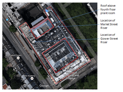
Aerial view of LSHTM. The red line demotes the outline of the building which used to form a capital A shape. The two hollow sections of the building have now been filled in.
The client, LSHTM, therefore wishes to install two new, appropriately sized boilers at fourth floor level and take steam back down the building to serve various loads. The existing system will stay in use and only be stripped out once the new system is fully online. This will require a period of gradual handover from systems as individual loads are brought online. The project is valued at £1M and the consultancy fee is a fairly small £50K.
The BWL team looking at this project is 3 strong; a director who effectively brought the job to BWL when he moved company, myself as the mechanical lead and an electrical engineer. The project is mainly mechanical in nature and the director is keen to take a hands-off approach, so I’ve essentially got a huge degree of responsibility and autonomy on the project which is great.
Steam
Before I go any further it’s probably worth explaining a bit about steam, although I won’t fully explain all the concepts this will end up like War & Peace. The following link is very useful and informative if you get involved with steam design at all or want more information:
http://www.spiraxsarco.com/Resources/Pages/steam-engineering-tutorials.aspx
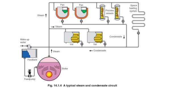
In normal mechanical systems it is usual to see a flow and return pipe. This is the case when dealing with steam except that the flow pipe contains your steam, which is dry saturated steam (steam that has had energy added to it so that it is completely dry) and the return contains something called condensate. Condensate is generated when the dry steam is subject to a change that allows it to change state to a wet steam of liquid. This change in state can either be caused by a drop in pressure or temperature. The change in state can be deliberate – the steam is being used in a processs e.g. through a heat exchanger or unwanted, e.g steam running along a pipe cools and condensate is generated due to the loss in energy. What we don’t want to happen is for condensate to build up in steam lines (impacts the performance of heat exchanges, is corrosive and can lead to water hammer damage), therefore condensate is removed using something called a steam trap. We also don’t want to waster condensate if possible as it still has energy within it which we can reuse at the boiler / generator and is valuable in that water going into a boiler needs to be treated. Reducing the amount of new water required by recirculating condensate reduces costs massively.

What have I done to date?
I’ve surveyed the site and produced a basic REVIT model of the plant room that we need to put the new boilers. In conducting my surveys I’ve also identified that one of the AHUs being served by steam isn’t utilising the steam (valves isolated and pipes cold), I’ve since spoken to the facilities manager who has confirmed this has been the case for two years. This has allowed me to removed the AHUs from the steam load profile a saving that allows me to drop down a model size on the boiler and save the project up to £50k – not bad for just having a walk around. I’ve just pulled together and submitted a Pre-Qualification Questionnaire and mini-tender document for the purchase of the steam boilers which goes a long way to filling the short falls in my C competencies from phase 2. Next stage is to move onto a bit more detailed design and start sizing pipes.
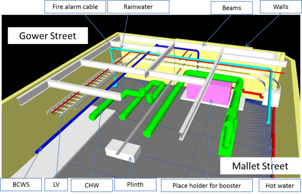
Basic REVIT model exported to NAVISWORKS to show the constraints within the fourth floor plant room.
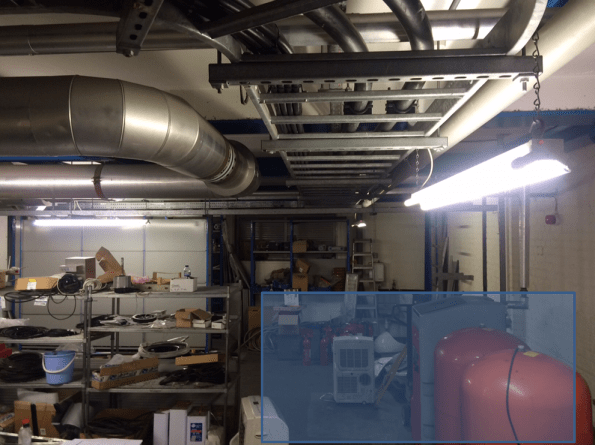
View within the fourth floor plant room where the new steam plant will go (denoted by the blue square).

View within one of the existing risers. This is the better set out of the two, the other looks like someone has just thrown pipes and wires in. There appears to have been plenty of expansion over the years but not stripping out. There are also no as built drawings or schematics, which when services are incorrectly labelled makes coming up with a plan interesting.
