Archive
Anywhere but Chatham…
Phase 1s,
Following up from Fran’s blog about Perth I thought it worth mentioning that there is a wealth of information in the blog archive about transitioning to phases 2 and 3. Looking back you will see that the blog has been a cathartic release for students past and present to whine about their experiences both overseas and when venturing out of the Army cocoon in the UK.
USACE:
https://htstrial.wordpress.com/2015/04/16/usace-not-a-place-in-china/
https://htstrial.wordpress.com/2012/03/23/progress/
Matt Fry had some difficult administrative times and is very articulate in presenting them!
BP:
https://htstrial.wordpress.com/2015/04/20/lang-time-nae-see-far-hiv-ye-been-min/
https://htstrial.wordpress.com/2014/04/21/getting-started-in-aberdeen/
For the design office to come:
https://htstrial.wordpress.com/2014/02/20/what-colour-is-my-parachute-or-do-i-have-add/
For anyone ending up in the US Brad and I have tried to ‘tag’ our posts so that they are a little more sortable. It may be something we could do in the future to separate the E&M blogs from the unending pictures of concrete too.
The blind leading the blind.
I have now started my design attachment in the USACE’s Baltimore District Headquarters and am currently working on two projects. One of which is a ‘server room’ cooling survey at Fort McNair in Washington DC, which this blog will focus on outlining.

Fort McNair, in the heart of Washington DC. As you can imagine the traffic was delightful.
I have realised my utility, I am cheap, and so have used this to secure some responsibility early. The project budget is $50,000 and, in the mechanical section, the average engineer’s time is billed at $135 per hour. The basic sum on this gives an engineer 370 hours, but add in project manager time, vehicles and other overheads and it can soon be eroded. This is something I will research into for a further blog but the upshot is that this is now my project, and a handsome little mess it looks like to. The scope of the work currently is to write a report on the cooling within a number of server and communication rooms within the Military District of Washington (MDW) office buildings. There are 15 different rooms spread across 8 buildings, built circa 1900, all with vastly different loads and in different conditions.
After meeting with the USACE project manager, the client and the HVAC engineer for the buildings, Don Ruhl (my partner from the mechanical section) and I toured a number of the rooms. As we travelled around it became apparent that not only did the client not know what they wanted; they also didn’t know what they had in the rooms. The photos give an idea of a couple of the rooms and the varying conditions.
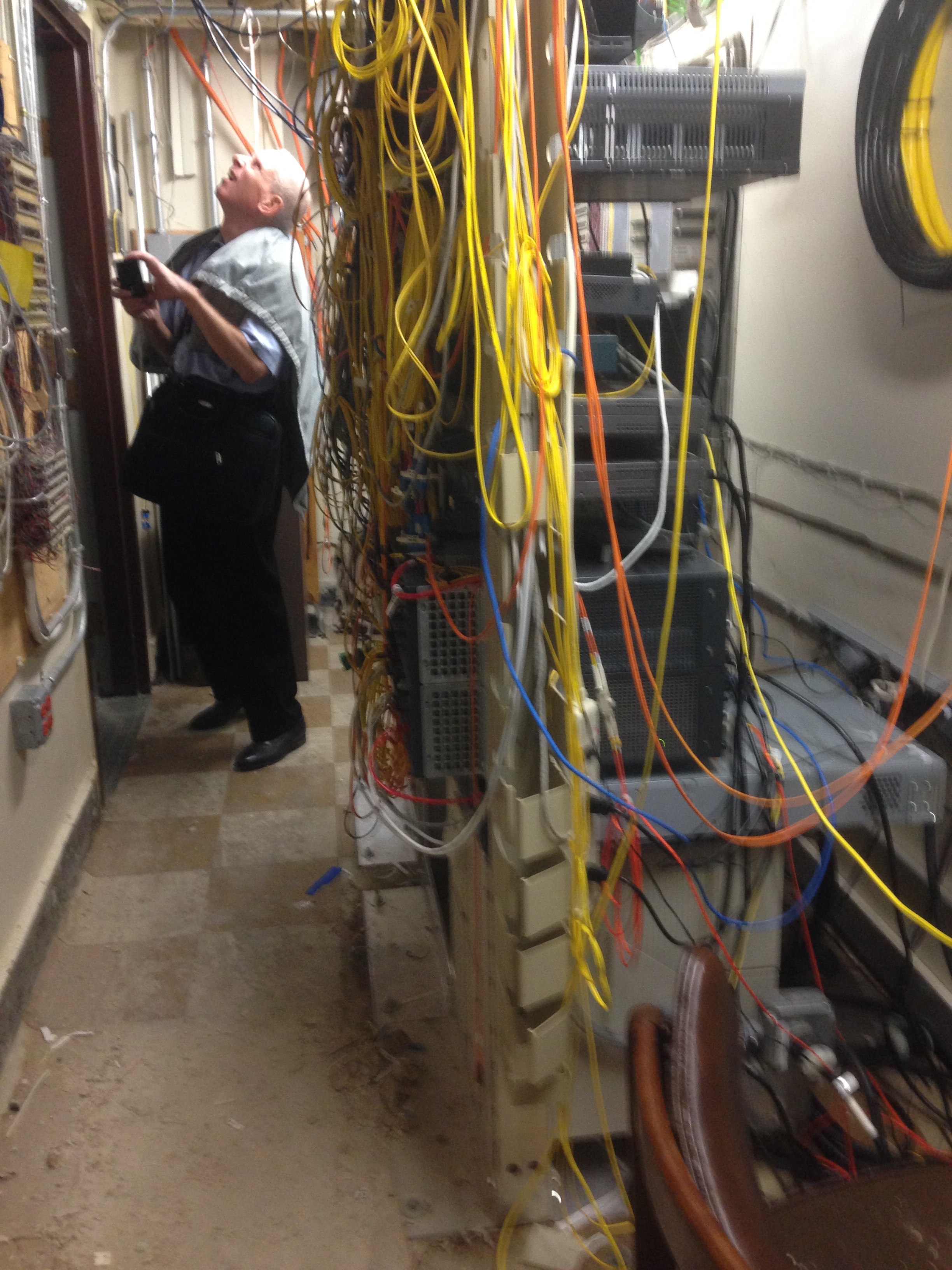
Don inspecting the many unsealed penetrations in a small converted basement broom closet. This room had about 12U of switches and had a retrofitted ductless cooling system. It also had a condensate drain to a sump, thus allowing the condensate to re-evaporate and continually cycle through the cooling system.
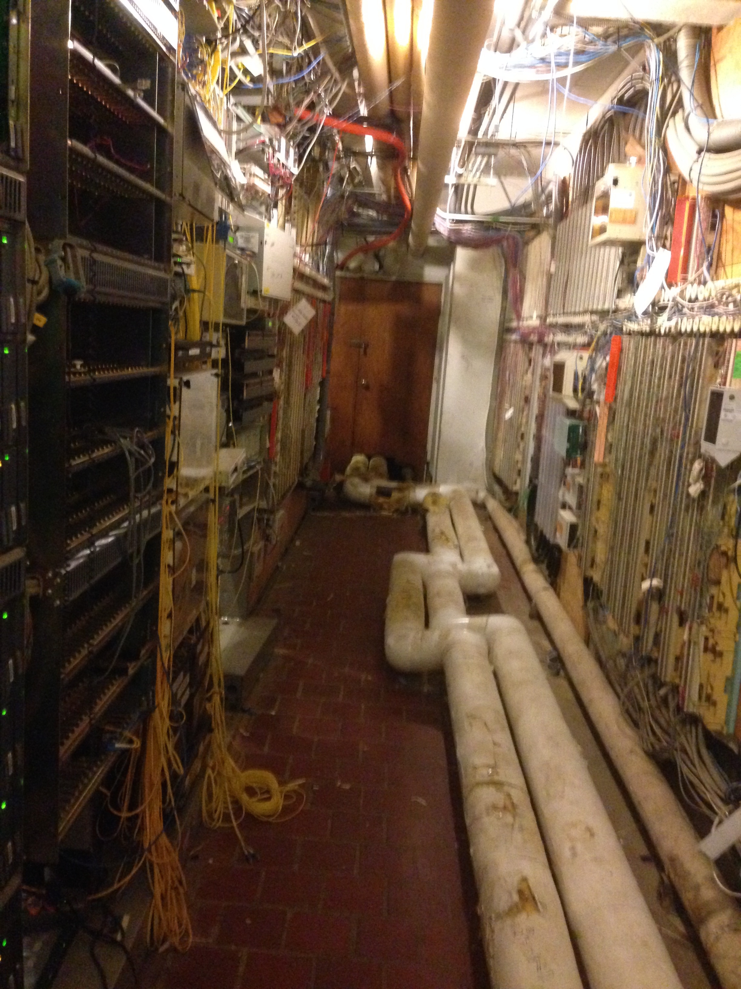
Another basement room with abandoned hardwiring to the Pentagon. About 45U of high grade servers in here. The pipe on the floor is for chilled water with heavily damaged insulation allowing condensate to form on it in the summer.
Server rooms are ideally internal within a building in order to avoid solar heat gains and also because servers don’t need a window to stare forlornly out of. They are usually sealed from infiltration; tidy, to control airflow and have some form of HVAC. The current standard for low and medium density data centres and server rooms is to use a hot aisle, cold aisle system as illustrated below. Cold air is fed from low down in the ‘cold aisle’, either through the floor or by retrofitted ducts; the server blade draws it in through the front and rejects warm air through the rear into the ‘hot aisle’. This rises and is collected by the return air system. As the photos above indicate this was not the case.
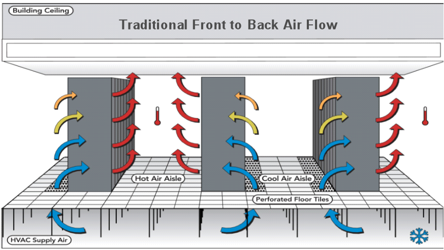
Hot aisle, cold aisle process diagram.
So what. Well given the conditions in many of the rooms, even doing a complete survey would be incredibly costly on time. After this initial assessment we need to engage in some expectation management in what we will be able to provide and re-write the scope of our work, which is currently pretty open ended. I see this largely as focusing effort on the more important rooms in terms of upgrades and identifying the risks of each room to the client so that they can make an informed decision.

In an age of BIM, I have been told that the best we can get is a floor plan for some of the buildings so it appears that even a set of out of date as built drawings are a wish too far. Due to this if construction work is ever completed on this then the contract will almost certainly have to be a design and build as the potential for change orders on a traditional contract would be immense!
Finally, a little leadership challenge.
I mentioned earlier that I had been given the lead on this project but I am working with another engineer. Don has worked for USACE design section for at least 30 years and is probably the most intelligent person I have met out here. He has no aspirations of leadership and is very happy to let me control things; however his ability to take a tangent and dive too far into the details too early are something to behold. Certainly a different management challenge from both soldiers and contractors!
RE Wall Upstream Walkway and Piezometer Installation; A simple task…
The Reinforced Earth Wall (7.2 x 6.2 x 500m) that is currently being installed on top of the existing Earth & Rock-fill Dam also requires a small walkway on the upstream face. This is required to allow for the inspection of the settlement points as well for monitoring the RE wall itself (panel verticality/movement and for extracting the internal galvanised test straps).

DESIGN
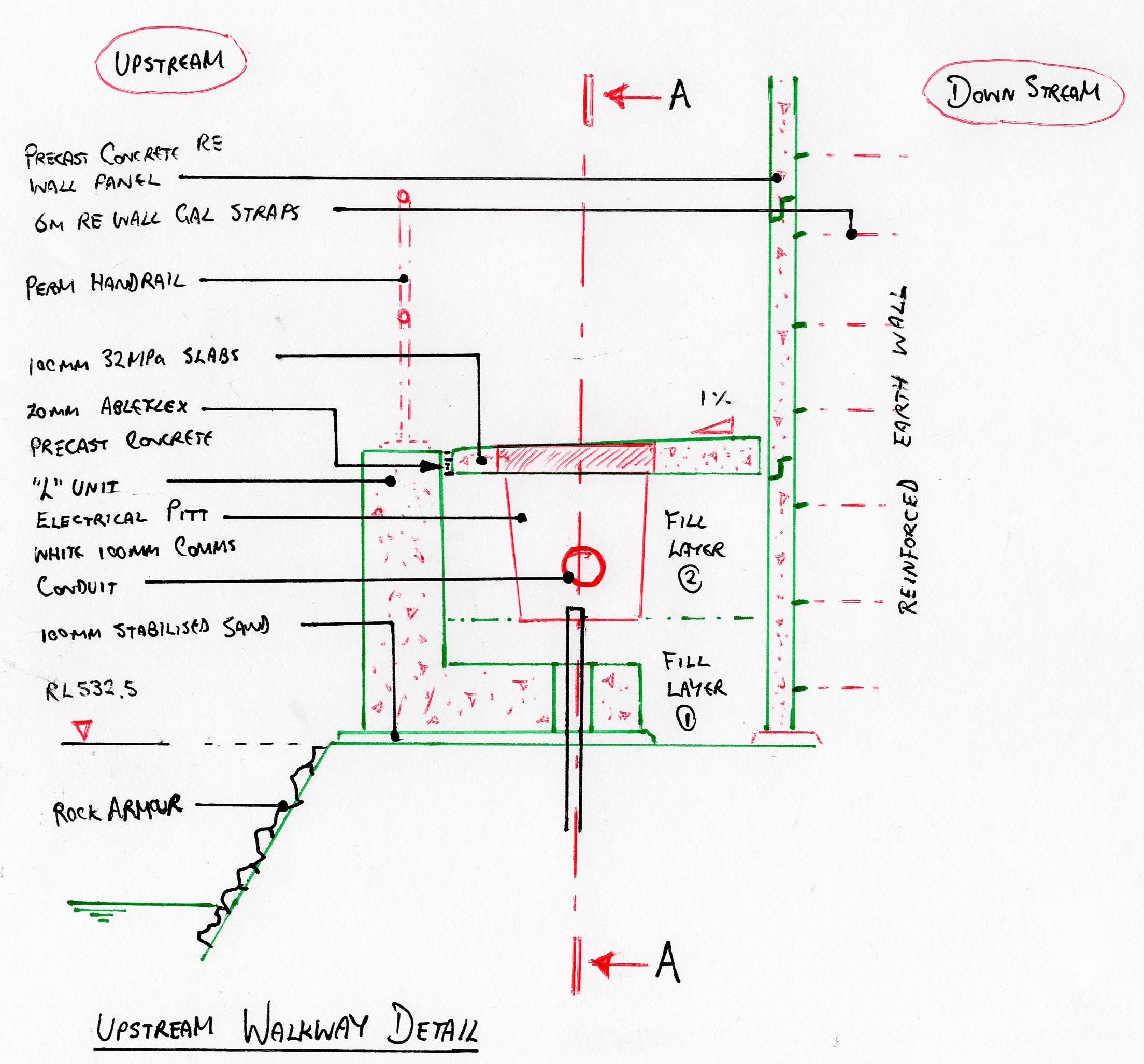
EPSON MFP image

METHOD
- Placement of stabilised sand (100mm). This was simply to provide a firm level surface for the L-Units to be placed upon as the large, angular 4B material produced an inconsistent surface level. It also allowed the temporary handrail to be secured in placed.
- Installation of temporary fall prevention system/ handrail.
- Backfill of rock armour on upstream face. Required to cover the stab-sand and improve aesthetics (..and durability)
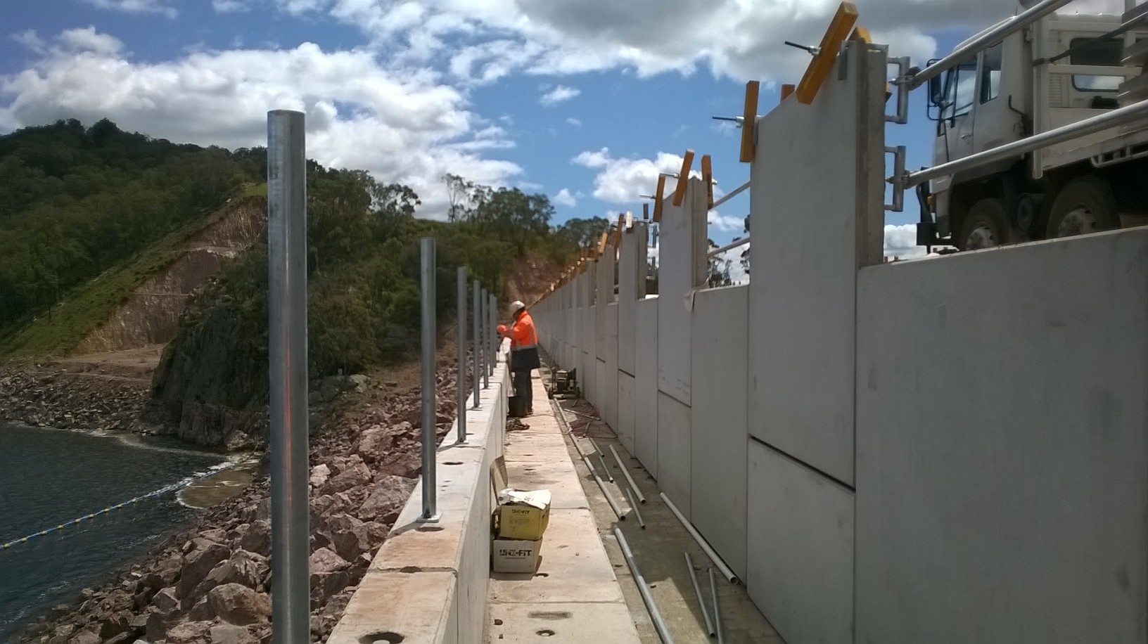
- Installation of precast L-Units. (see photo 1). Originally, designed to be gabion baskets, these precast units were favoured for aesthetic reasons. The finish and uniformity of the units was flagged as being very low.
- Removal of temporary fall prevention system. (Design of fall restraint anchor required- see below)
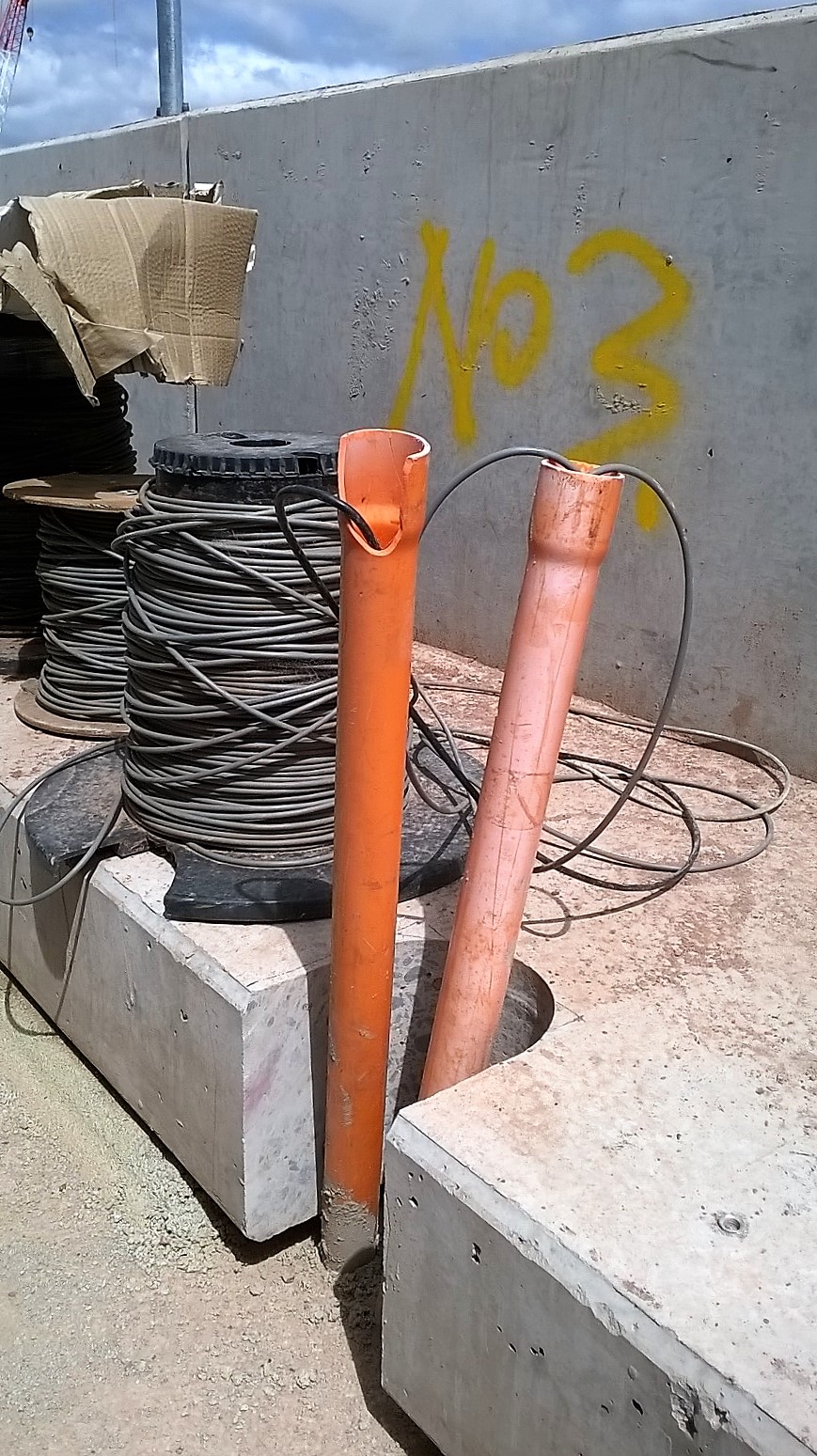
- Core drilling of L-Units to allow piezometer conduit to pass.
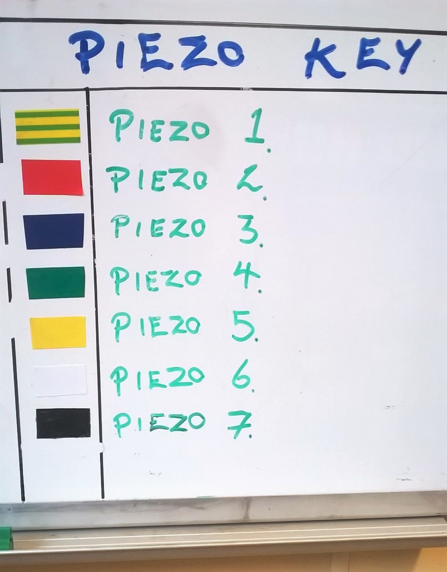
- Piezometer marking/ protection.
- Installation of permanent handrail to top of L-Units.
- Backfill of precast concrete L-Units using large rock-fill material (Layer 1 (0.45m)). Agreed upon by SPE due to large cobble aggregate to be used (20 – 75mm).
- Installation of plastic electrical pits.
- Further placement and compaction of backfill material (Layer 2 (0.45m)).
- Installation of pavement formwork, steel reinforcement, jointing, end stops.
- Construction of concrete pavement (310 x 1.6 x 0.1m).
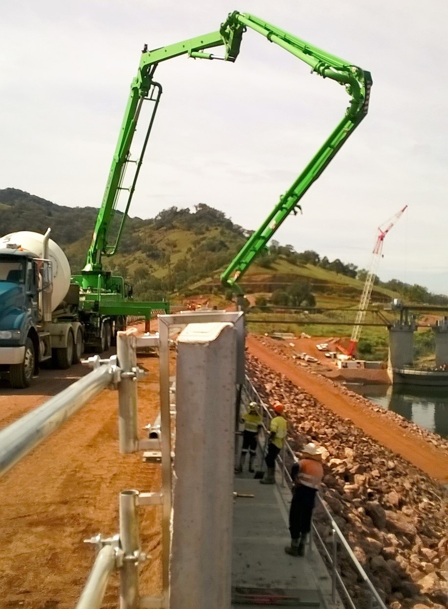
Point Loading the RE Wall. I assessed that the pumping of concrete from an unfinished RE Wall to a walkway 3m below was the greatest risk to this phase of construction. A 36m pump would be positioned onto the RE Wall crest in order to pump 12 x 6m slabs/ day. Each outrigger leg was rated up to 192 kN but with the walkway so close, it was assessed that this force was unlikely to be approached. Upon receiving the concrete pump technical data, it at first appeared as though we would not have sufficient space (See image below). Fortunately, this was not the case and it was able to safely operate simply using an alternative outrigger configuration. The important dimension was that of the 1.5m exclusion zone from the internal face of the RE Wall within which the outrigger could not encroach. This was likely due to the lack of frictional resistance offered by the steel strapping at such proximity to the RE Wall Face which prevents the vertical panels from pushing out.
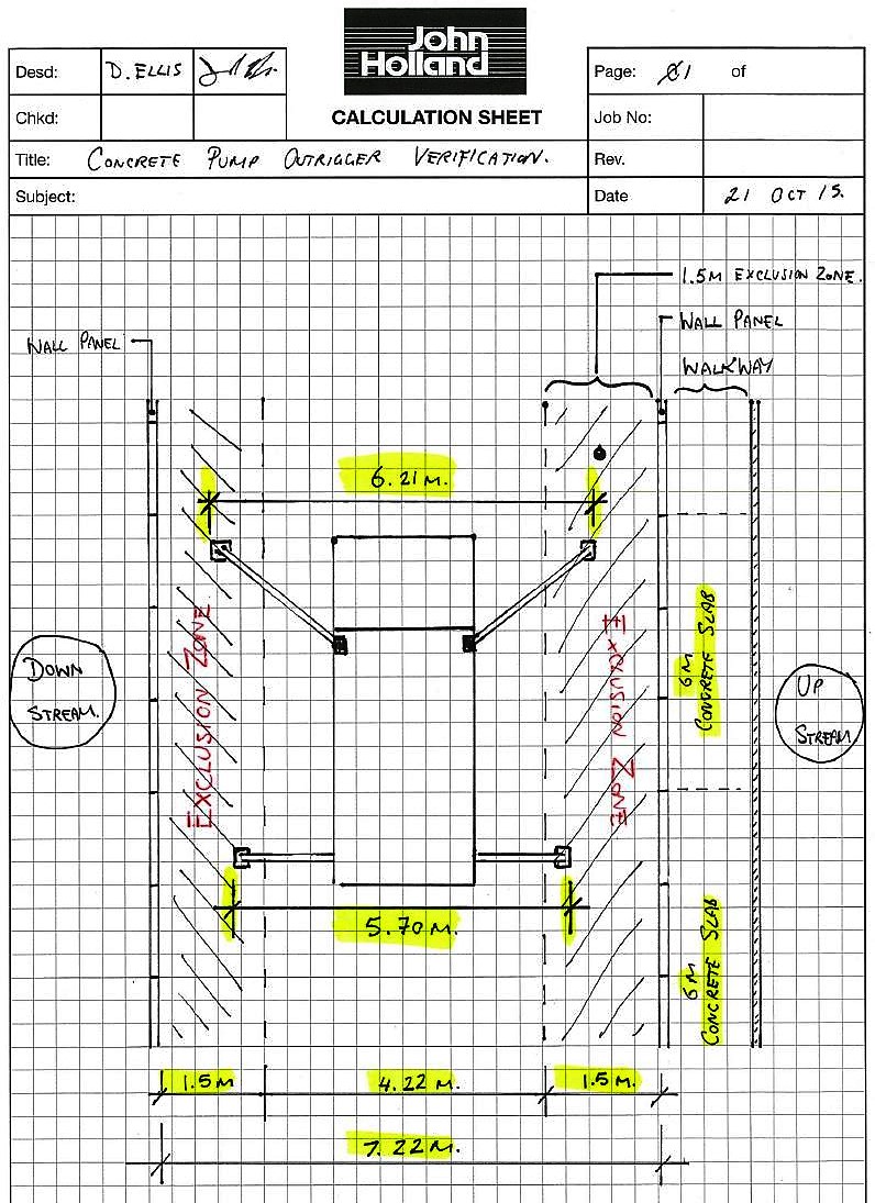
Outrigger dimensions breach RE Wall exclusion zone
Working at Height. Due to the steep upstream face, a temporary handrail was installed to provide a fall prevention system. Once the L-Units were in place the temporary handrail was to be removed. However, workers were required to wear harnesses for the removal of the handrail as it required them to step on the outside of the L-Units.

Due to the lack of fixing points, I was required to design a fall restraint system. M16 5.8 bolt was used with a small steel plate to provide an anchor point for harnesses. The simple anchor design required external verification before it could be signed off. A couple of hours later and the design was approved for immediate use.
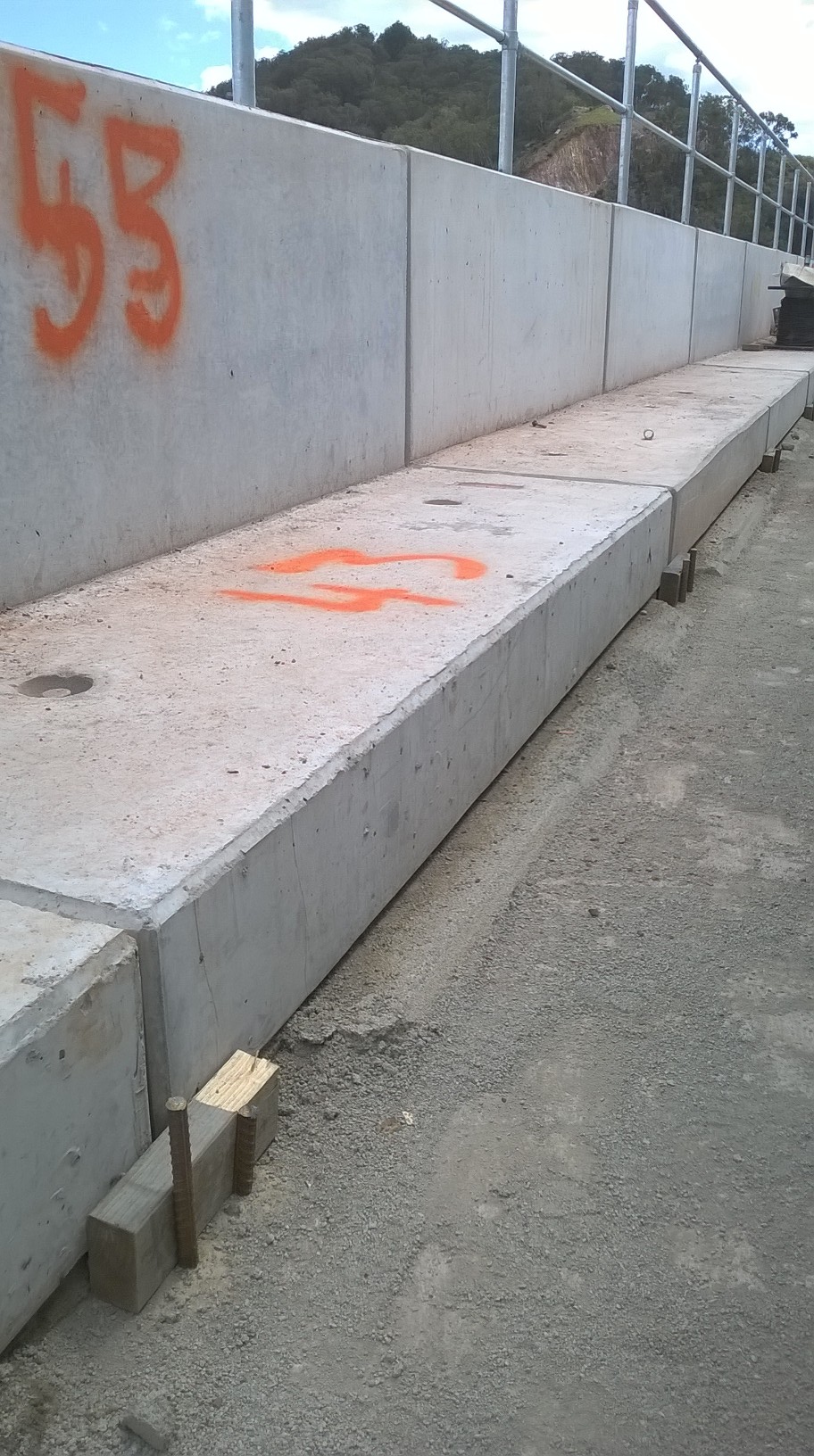
Securing the L-Units. As part of the RECO L-Unit system, hot dip gal sheer keys are provided which meaure 1m in length. These slot vertically in between each concrete unit and ensure that the individual units operate as a continuous structure, whilst allowing a certain degree of movement. However, due to the subsequent placement and compaction of the cobble fill material between the RE Wall and the L-Units, I decided to pin them in place using 4 x steel rods as shown below. This was to prevent the units moving laterally away from the RE Wall as compaction occurred.

ISSUES
Piezometer Alignment. When initially setting out for the installation of the walkway, it soon became apparent that the piezometer alignment would conflict with the position of the precast concrete L-Units. Consequently, 100mm holes had to be drilled through the precast units to allow the piezometer conduit to pass through. As JH were also responsible for the location at which the piezometers rose vertically during prior groundworks (and before my arrival!) it was a simple matter that could have been avoided.
Missing Materials. Despite being fully assured by my predecessor that all components were correct and present I was a little under the moon to find out that approx. 10m of handrail fixings were not accounted for but an additional 30 vertical post were present… A swift call to the manufacturer and all was well.
LESSONS LEARNT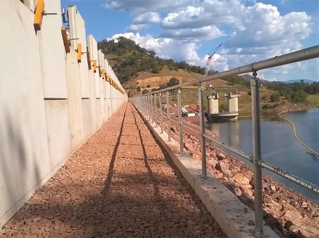
5 x P’s!! – Poor planning lead to several avoidable issues during construction. ie. Precast L-Units requiring core drilling (5 x 100mm Ø holes) to allow for the Piezometers to pass up vertically to the surface of the walkway.
Precast Unit QA – Do not rely on consistent geometry of precast unit in planning.
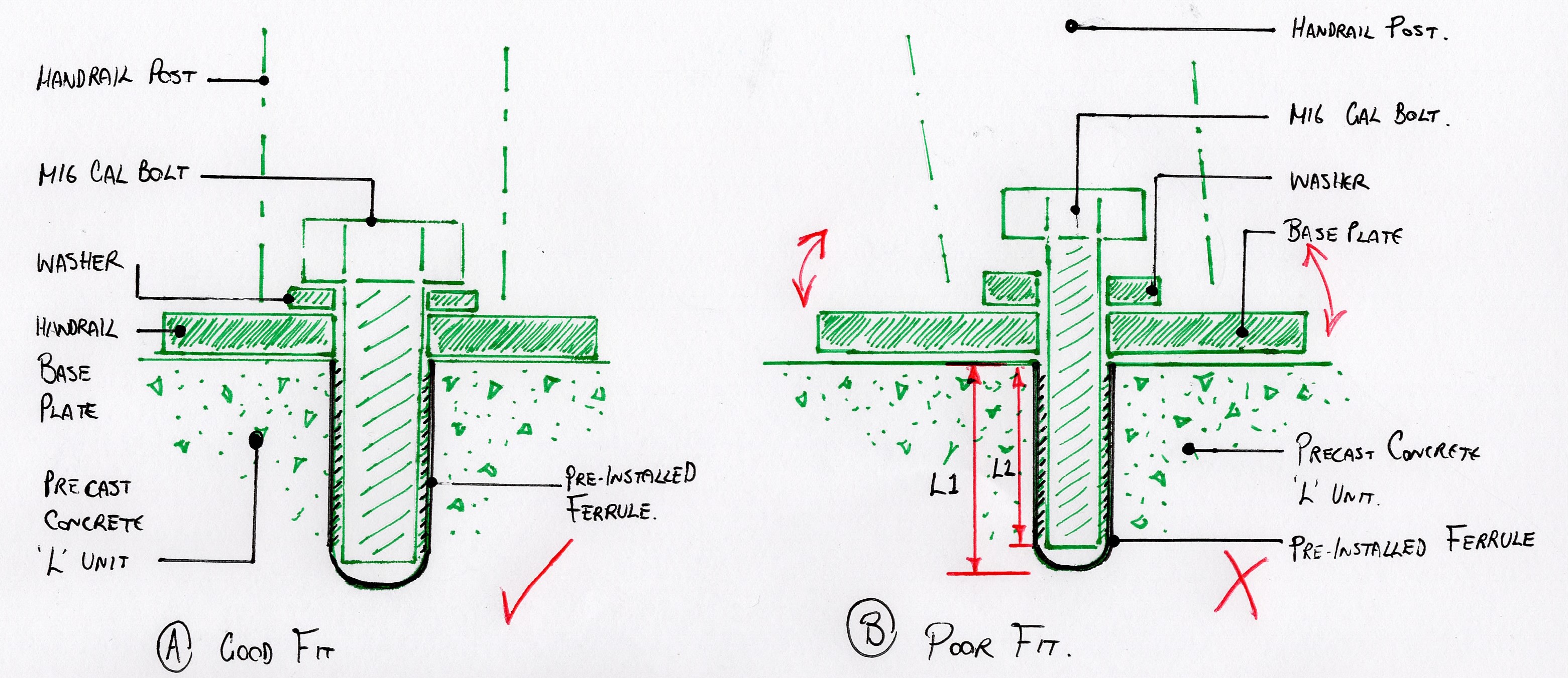
Each of the precast L-Units has 2 x preinstalled ferrules. These provided a metric thread fixing point in precast concrete panels to which the permanent handrail will be installed. Due to the lack of conformity in the geometry of the precast units, the horizontal alignment of all the ferrules once all of the L-units was far from straight (even by Aussy standards). The final handrail would have looked terrible. As such the decision was made to drill and install new ferrules in order to achieve an aesthetically pleasing handrail alignment. See final alignment above.
Check and Double Check material quantities!!
Reo Bar Chairs – Ordered 1000 x 45mm plastic bar chairs to sit on the uneven 4B material. Thought to be too many but required more 75% way through bay construction. Underestimated spacing required due to uneven 4B material…
Bolts and Ferrules. To determine the bolt length that was required for a pre-installed ferrule which is not detailed on the drawings, do not simply measure the ferrule depth using a steel rod (who would do that?..). As the base of the ferrule is rounded, the depth that a bolt can actually penetrate is approx. 5-10mm less than the full ferrule depth. If a bolt then protrudes greater than required the handrail baseplate will be loose (apparently..).
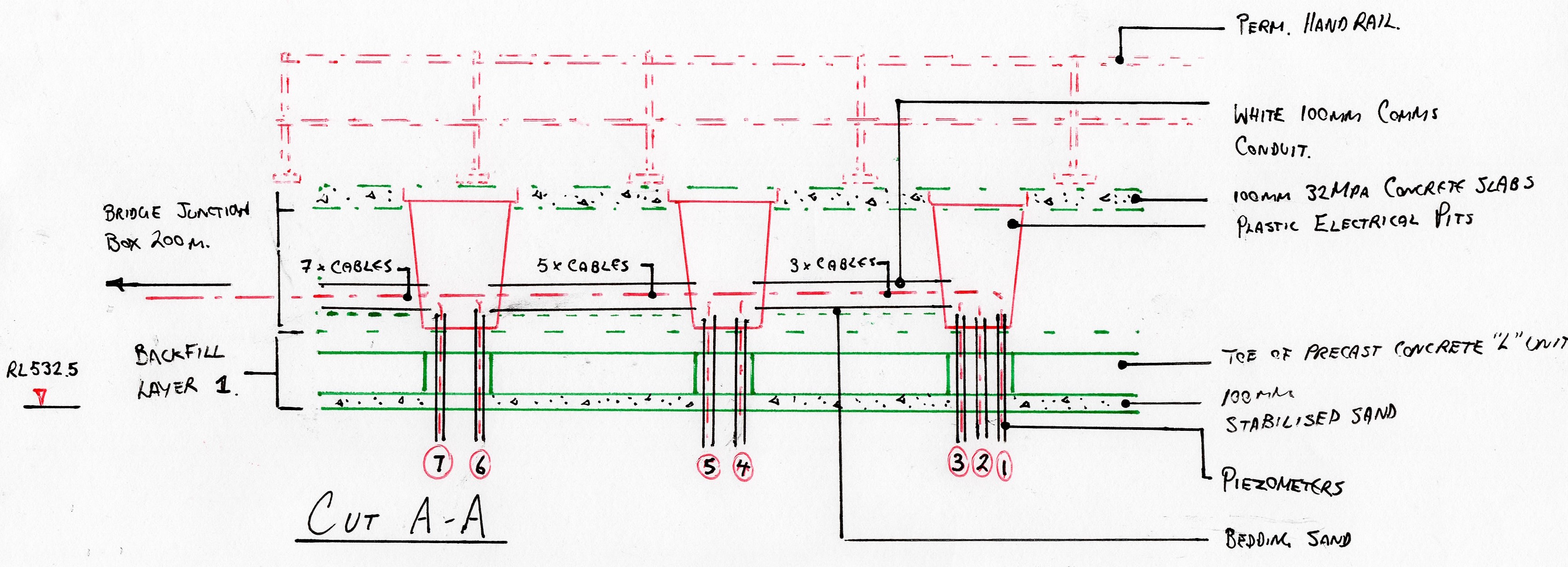
EPSON MFP image
OTHER NEWS..
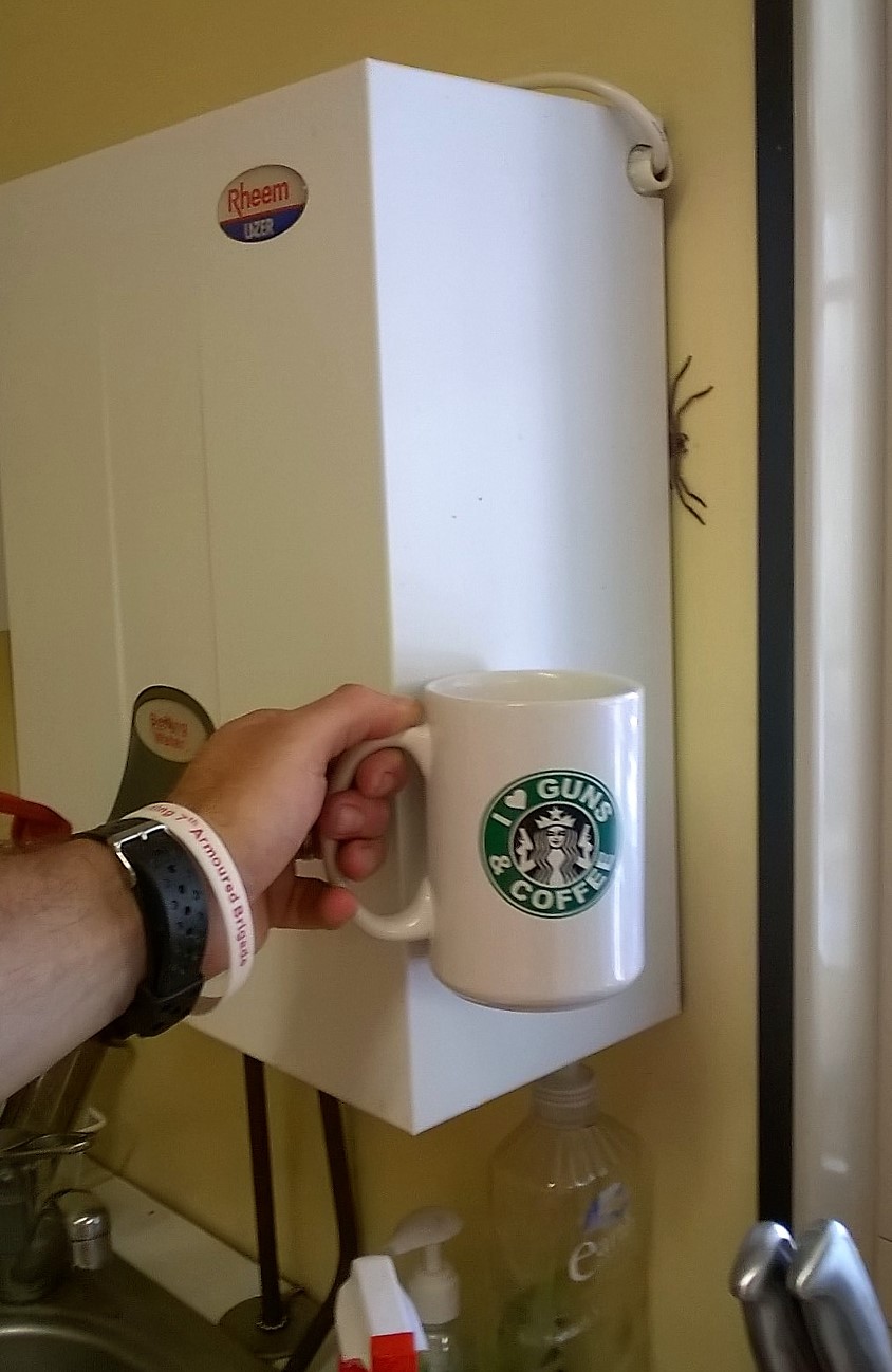
New Chaffey Dam Site Office resident fancies a brew!
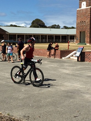
Oz PCH – Chatham to Perth

From this…

…to this!
Introduction
Now that the Phase 1 students have been informed of their Phase 2 attachments I thought I’d blog about my (and my wife’s) experiences on initial move out here to Perth. I actually got my wife to write this after being here for a few months so it will not discuss any John Holland work related aspects. If anyone does actually end up in Perth on a John Holland project then I will be happy to discuss any specifics separately as the likelihood of working with some of the same people is very high – there is only one new project in Perth that John Holland are currently tendering for.
Despite being the second most isolated city in the world; after Honolulu, Perth really is a wonderful place that has something to offer for everyone no matter your interests or preferred life-style. We have had a wonderful time so far and thought some of the things we have learnt in this first month may be of use to others. Firstly, there are some things you can do from the UK that will make your trip that bit easier. The main one would be to organise an Australian bank account – we went with Commonwealth Bank [they have a very handy smartphone app and have lots of branches doted around]. This can be done from the UK and all you need to do when you get here is head into the nearest branch and finalise some details. Make sure you take your passport for this as UK driving licenses and Military ID are often not accepted. [All this information and more can be found in a PowerPoint presentation on the PEW SharePoint].
Travelling
You won’t have too much choice on airlines but you will be able to decide if you would like an overnight stop. It is important to remember that unless you have children you will have to pay for this out of your own pocket. [Qantas has announced a non-stop flight by 2017, see link below, but to be perfectly honest a few hours transfer in Singapore is no drama at all and I can recommend Singapore Airlines].

Great airline and easily within the Army allowance.
Weather
We arrived in autumn [March] and the weather was gorgeous. Locals grabbing for their coats but you won’t need anything more than a thin jumper in the evenings. [Hot enough to call it a British summer that’s for sure].
Initial Stay
We were put up in Quest Apartments for the first month. It is worth doing a little research before you leave so that you can suggest where you would like to be living; coast or city, dependant on distance from site of course. We were in Scarborough (on the coast) and although it was a little far from work [I wasn’t working for the first 3 weeks] it was a lovely vibrant place to stay with plenty of restaurants and a stone’s throw from the beach. These apartments provide a charge back service so that we could eat out and charge it back to our room where John Holland picked up the bill – very handy and definitely recommended.
Driving
Although the buses and trains are relatively good in Perth it is preferable that you have a car as things are quite spread out here. There is very minimal traffic on the roads even in rush hour but you do need to stick closely to the speed limits, which are significantly lower than in the UK (on avg 50 and 60 kph on main A-roads), as the police are very vigilant and like to set-up mobile speed cameras; camouflaged and hidden behind bushes not like the easily seen yellow boxes in the UK. Make sure that you check with the car hire company [Hertz in our case] that they have your correct arrival flight times (we were delayed slightly) so after the long journey over you have a car ready and waiting for you and don’t have to wait 45 mins like we did.
Parking
Although site specific, on-site parking is between AUD $20 – $25 (£10 – £13) per day, so cycling into work was preferred and made more enjoyable by the predictable sunny weather. Perth has some great cycling paths and on rainy days there are always the buses or trains that work well.
House Hunting
Finding a house was much harder than we thought. Our biggest issue was that 95% of rental properties out here are let as non-furnished. Back in the UK we thought furnished would be much easier – but be aware this dramatically limits availability. You need to weigh-up whether you think it’s more hassle to ship furniture over/buy some when you are here and use the Army buy-back scheme or spend longer looking for a fully furnished property. We have been persistent/lucky and stuck with looking for fully furnished and have found an awesome three bedroom house 8 min walk from the beach.
Finding Work [for the wife]
Being a teacher we thought it would be easy finding work; on the contrary, it was extremely difficult but mostly due to the education system here being set-up differently and there is definitely a clique of looking after their own first. Make sure that if your partner intends to work that they do extensive research into the requirements of that profession. Bring all your original qualification documents in case you have to send off copies to prospective employers as they will have to be officially certified. There are plenty of schools though just not that many jobs. Relief work, managed through an agency, is the best foot-in-the-door way to secure a full-time position.
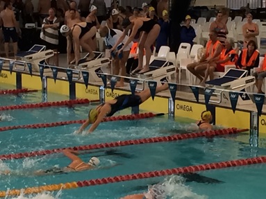
Fitness
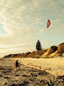
If you are into fitness [which you should all be] you will be spoilt for choice in Perth. We fully intend to try everything [and have had a good stab at most things so far] and have already fallen in love with stand-up paddle boarding. [Being a tri-athlete there are some great clubs in Perth, mine being Stadium Triathlon Club. This also extends to purely swimming (my wife is a member of Claremont Masters) and cycling clubs; which are all plentiful and very well attended. To that end, if you are a cyclist or think you might like to cycle out here, and I’d suggest you do as it’s a great way to explore Perth, then definitely ship your bike(s) over. Fitness is part of the culture out here and everyone goes to bed early so they can get up early for a pre-work session; massively helped by the utter rubbish that is on what they call TV. Even at the weekend you will see a lot of people up at 0600 walking dogs, running, cycling and swimming – it literally is a Mecca for sports!].
If anyone on attachment to Oz would like any more info please drop me an email franrizzuti@hotmail.com
State to State will vary somewhat for which it will be best chatting to the others out here once you know exactly where you’re going but any general questions are very welcome.
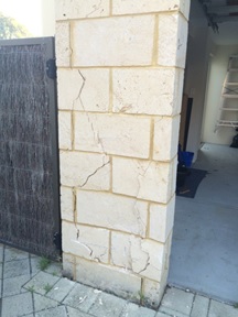
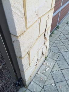
In Other News
This is what happens when a neighbour reverses onto your driveway to let another car past but accidently puts his foot on the accelerator instead of the brake!
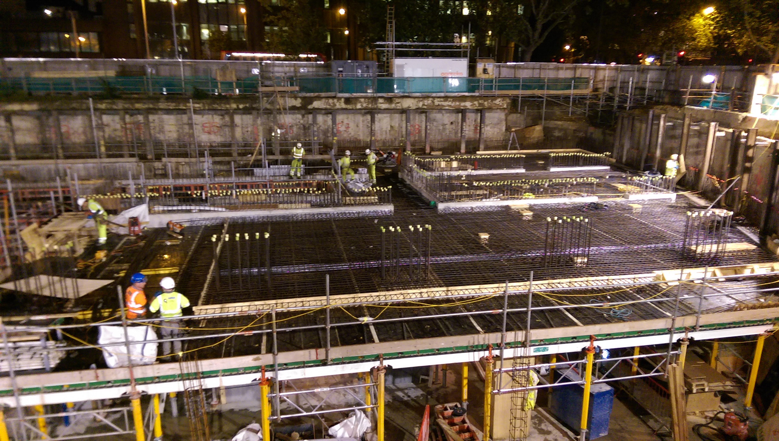
Site Two Fifty One – A few examples of how things can be done.
Site Two Fifty One – A few examples of how things can be done.
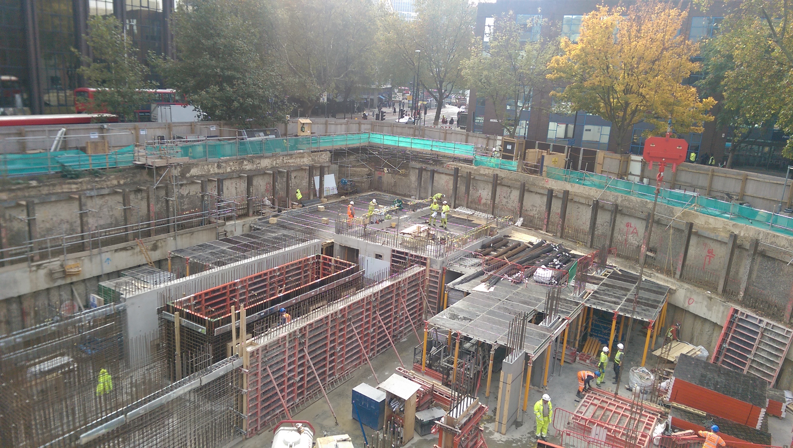
This is just a quick blog with an update of where things are on site. If there is an area of interest I will expand/find out answers in the comments.
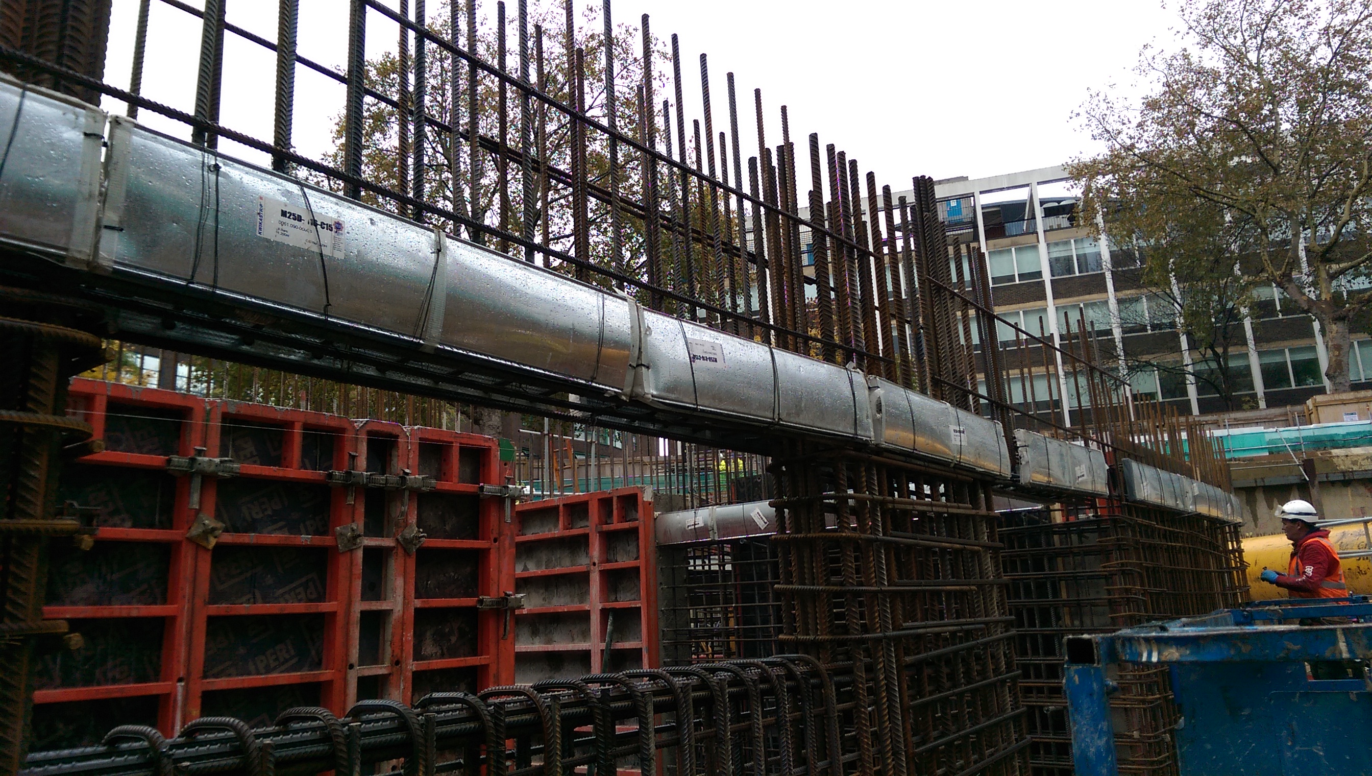
1. Kwika strip slab starters. As previously mentioned we would be using kwika strip in the walls. This shows how they look pre-pour. The bars have about 30 mm cover within the case.
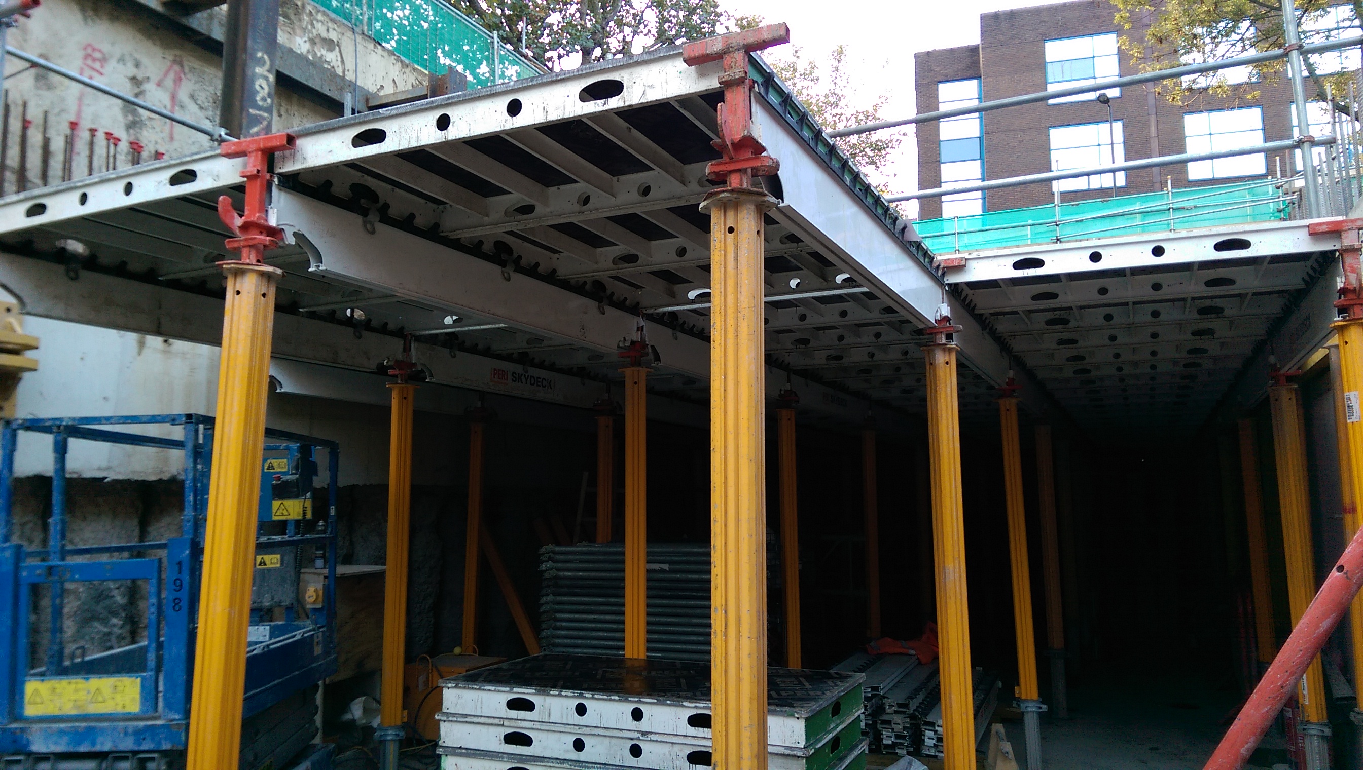
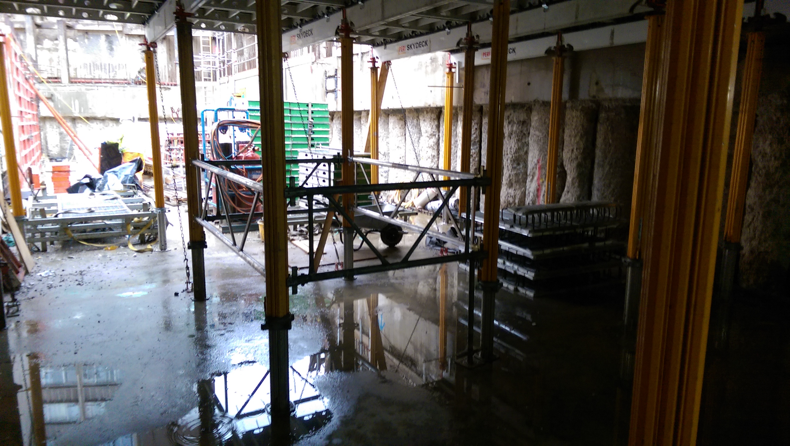
2. Sky deck falsework. This is a Peri system which is quick to erect. It requires bracing using chains and a section of trusses to transfer 2.5% of the vertical load. We did not silicone between joints but used a plastic t-section. There was some grout loss down the faces of the walls and columns which was washed off to avoid disfigurement.
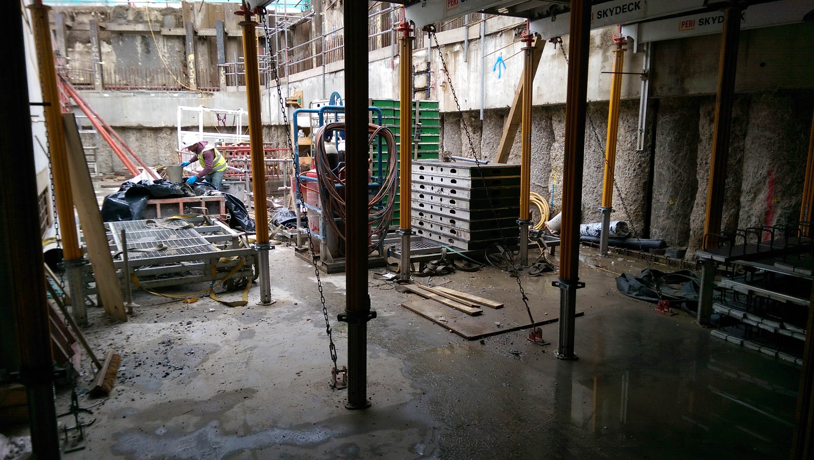
Chains providing lateral restraint of the Skydeck.
Braced panel to transfer vertical load to the ground.
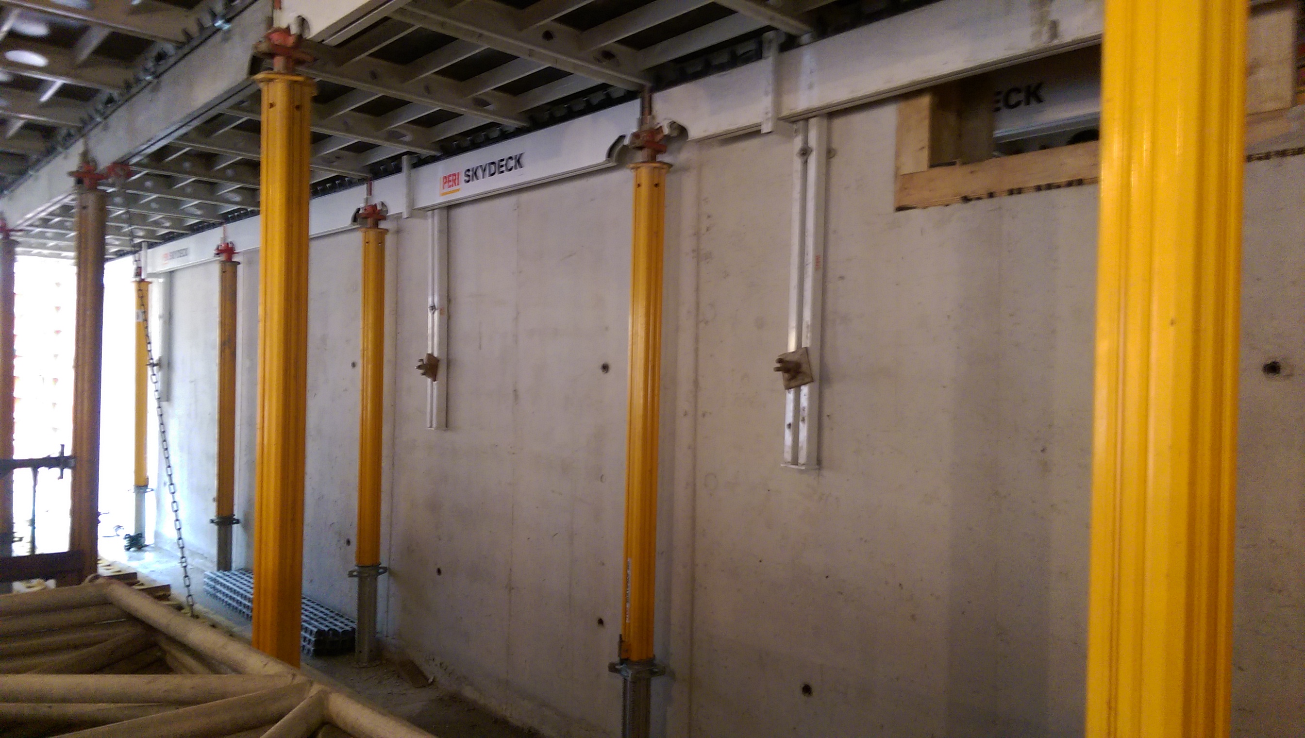
Wall brackets to provide lateral restraint.
3. When can I strike? The next challenge was to know when the falsework could be struck. The method used is based on a crack width assumption that compares construction loads with unfactored service loads against the concrete strength (fcu) (see page 186 in ‘CS30 Formwork. A guide to good practice, third edition, 2012’ for full details). This slab is for a plant area so the ratio is low resulting in the concrete strength required to be 15N/mm2 to strike which should be achieved in 4-days. However, we will crush cubes daily and have thermocouples placed in the pour and cubes, so we will correlate to give an accurate actual concrete strength, which if reached earlier than 4-days will mean we strike the falsework sooner.
Skydeck falsework being installed at B1 level.
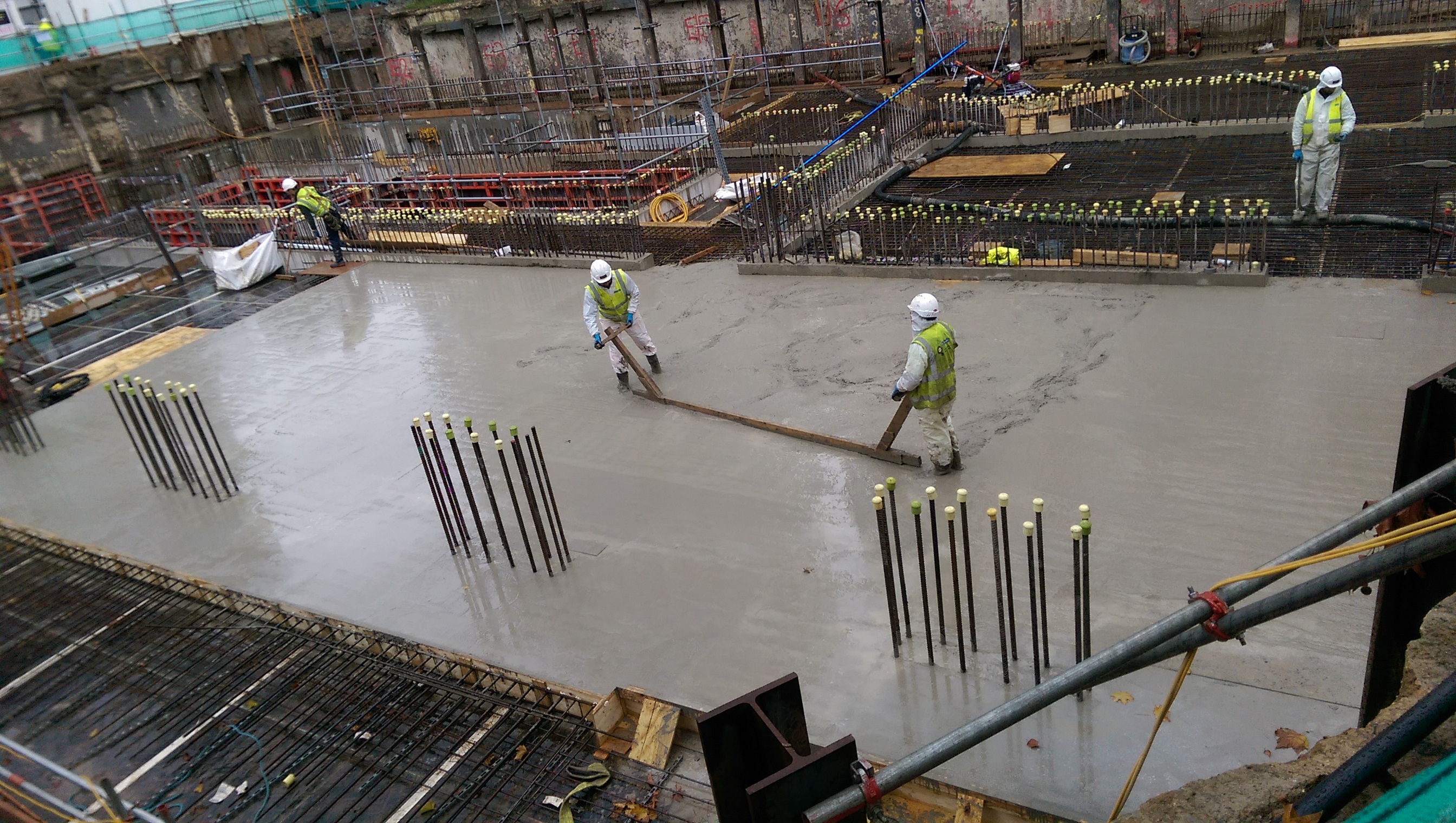
Slab pour – puddling complete around columns.
4. Concrete miss-match. Some of the building’s columns are 60N/mm2 whereas the B1 slab is only 40N/mm2. Therefore within the B1 slab pour a section of 50N/mm2 concrete was puddled around the column locations to avoid a miss-match in strength of more than 10N/mm2…
Hi-rib stopend at near-side of slab pour, near column starter bars.
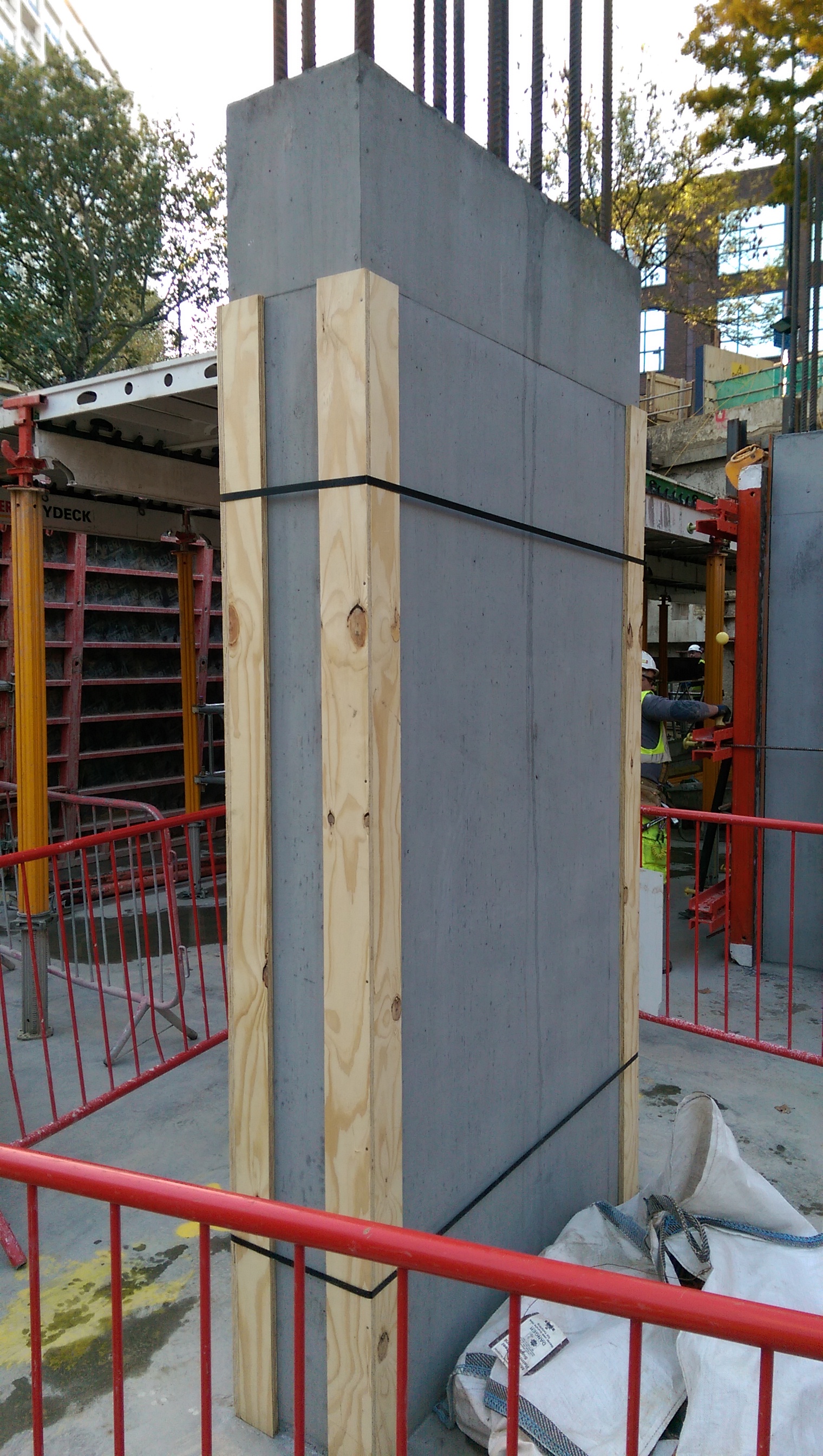
5. Column formwork. 2-sided formwork – props used to keep column vertical rather than taking significant horizontal load. The horizontal load is carried within the internal ties.

6. How do you build this? This is a sump 3.1m deep by 600mm . 600mm. To install any sort of formwork and then strike it would be too small a pit to put an operative in to work. Not necessarily the best solution but a quick one is to use precast sections (similar to manhole rings) to build up and pour the walls around it. The outer size of the chamber had to be increased but there was no spatial constraint to prevent this so hopefully the plan will work!

GRP Pipe Design
Design
The remainder of the GRP pipe line was installed by York Civil, using GRP with flexible coupling free issued by John Holland. The design showed that the pipeline would transition from a flexible pipe (i.e. the use of couplers and concrete thrust blocks) to a rigid pipe (i.e. fully welded) at the interface between GO scope of works. Originally GO were to supply all of their own GRP for the reminder of the underground and the above ground piping that leads to the pumps. However our procurement spotted a potential opportunity and decided to use the surplus GRP we had onsite to free issue to GO instead. This all happened during the tender stage, about three months ago.
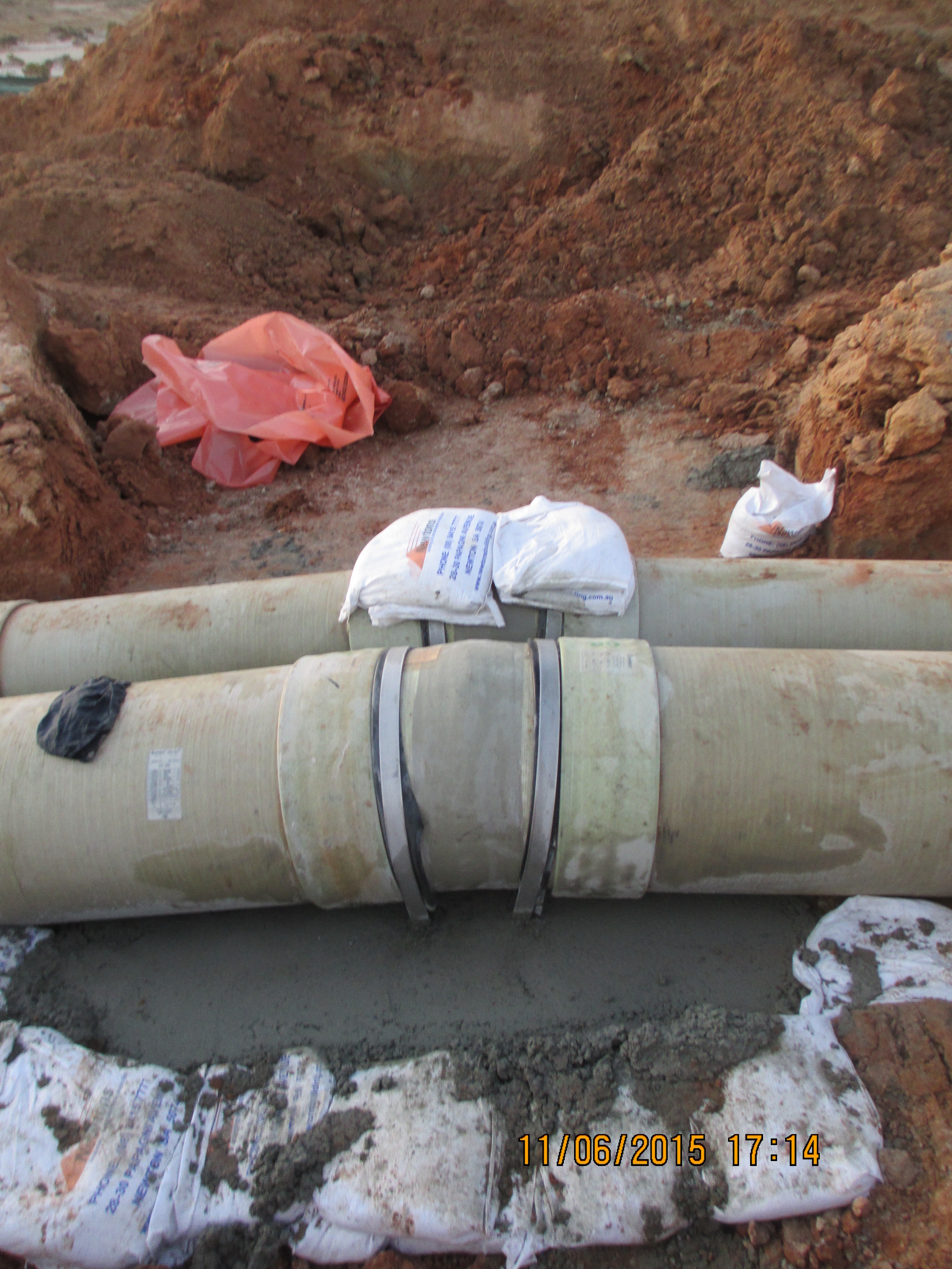
Flexible GRP Pipe Installation.
Above Ground Rigid Pipe
Issue 1
After arriving on site GO began some other packages of work and provided spool drawings for the GRP they were supplying for approval. During the design of this GRP the manufactures passed the design to a consultant for ratification. The consultant identified significant issues with the longitudinal strength of the pipe, which had been designed using the specification supplied by our designers (KBR). After this several discussions ensued on site between myself and GO, it became apparent that we had become messengers between the two technical experts (one in KBR and the other in the consultants) who had differing opinions. Eventually I was able to arrange for them to get in the same room and thrash the problem out. The final outcome was that the pipe needed to be upgrade at a cost of $45,000 to deal with the additional longitudinal strength. These longitudinal forces were due to the operation of the pumps and thermal expansion. KBR were able to argue the fact that there was enough information on the drawings for subcontractor to know this and even though GO were on a supply and install contract they had a duty to do some design. Luckily in the same meeting KBR were able to muddy the waters to such an extent over who was responsible for these changes that GO accepted the cost, rather than try and challenge it.
Issue 2
About a week after the above issue was resolved I received a separate email from KBR asking that I check the GRP we were free issuing to GO as there may also be issues with that. After speaking to the GRP supplier it became clear that the pipe would not be suitable for the current design. The design was then changed to switch the section of pipeline back to a flexible. With John Holland receiving a bill for the redesign and a $20,000 variation from GO, with further changes to the design expected this will rise. My role on site has been to manage this process and try to ensure design changes have minimal impact on the work already completed. The cause of this issue could easily be passed back to the procurement team for not checking the pipe would be suitable, however I think it goes deeper than that. The designers were aware of the plan to use the GRP but didn’t comment until GO raised the issue above. In addition the suppliers of the pipe had previously agreed it would be suitable without actually understanding the full design. Unfortunately it looks like cost of all these variations is likely to come to John Holland. Although I have already been tasked with trying to pin this on the designers.
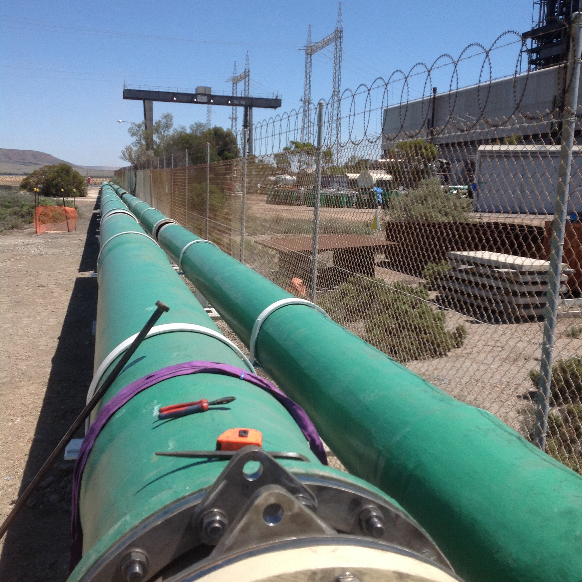
Issue 3
The more worrying issue was the fact that the same free issued GRP was used at the other end of the pipeline where it discharges into the lagoon. The pipe was wrapped to make it rigid, as shown on the drawing and using the wrapping methodology provided by the pipe supplier. Once installed the pipe was hydrostatically tested to 625kPa, a value given by the designers in answer to an RFI just a week earlier. Two days after conducting the test we received a further email from KBR requesting that we not test the pipe as it would fail under the pressure. Luckily the test went fine but the potential for injury was there and as such this has been raised as an incident within the John Holland system. Operationally the designers see no issues with the pipe as it currently is. The pipe is positioned 5km away from the pumps and is open ended so the pressure is deemed to be negligible.

Seawater Inlet Pipe
Conclusions
The design of GRP for pipelines is a specialist area in its own right. In the case of the site at Sundrop Farm it was clear that the designers at KBR were not fully aware of what they were doing in relation to the GRP design. The design and associated documents had a number of flaws which had they been scrutinised by a specialist would have been picked up much earlier, which in turn would have reduced the financial impact of the changes we are now having to manage on site.
With regards to procuring items the supplier needs to know as much information about the environment, system and operating conditions their component will operate in. Had the GRP suppliers understood the full system and operating conditions of this design they would have been able to provide more suitable product capable of operating as designed and reducing the impact of future changes. Instead they were responding to isolated RFI’s from the procurement team, thus providing answers which were not relevant to the situation.
From a site point of view it is difficult to see how we could have responded differently. We were provided with IFC drawings from the designers and pipe procured by our procurement team. The designs go through a review process both by the designers and John Holland. Had it not been for the subcontractor conducting a review of the GRP and us responding to the information they provided the installation would have continued as per the design. The impact of this is hard to quantify, the plant could have operated as designed for years or the GRP could have failed as soon as the plant was switched on.
In other news
I took a long weekend off earlier this month and took the opportunity to drive up to Uluru or Ayers Rock. The drive takes about 12 hours through the outback and is broken up with nothing apart from a missile testing range, the odd service station and Coober Pedy. To break up the journey we stopped at all of these and spent the night at Coober Pedy. The town’s main claim to fame was the discovery of opals in 1915. Troops returning from the First World War began to settle in the area from this date. Because of the harsh climatic conditions the settlers began to tunnel into the rock and build homes (called dug outs) underground.

Wilfred Pointing to His Christmas Present
Today the town has a population of almost 1700 and most of the towns building remain underground. The hotel we stayed in the temperature remained between 22 and 25 degrees all year round without the need for air conditioning, despite outside temperatures exceeding 40 degrees for much of the year. Natural ventilation is provided by a number of shafts that extend from each of room to the surface above. Each room had an umbrella positioned upside down under the shaft in the corner to catch dust landing on the floor. The wiring throughout the hotel was done by drilling horizontally, then using a vacuum to suck a piece of tissue with a piece of cotton attached and then pulling the cables through.
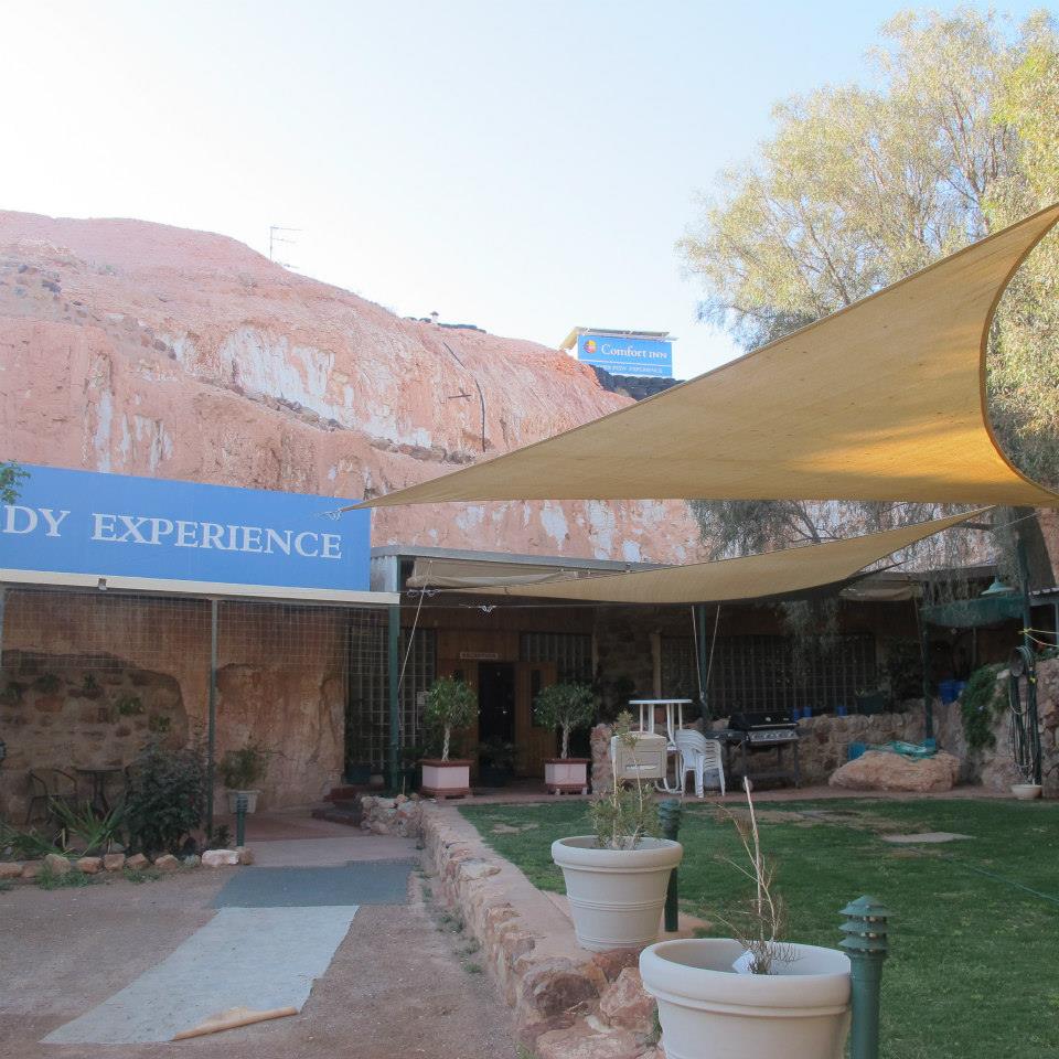
The Comfort Hotel Coober Pedy

Hospital Pass
Part of the role of USACE, as the client’s representative, is to conduct design reviews for design-bid-build contracts (read traditional contracts). These are done at 35, 65 and 95% with comments provided back to the project manager and design team, be it in house or a consultant, through an online system (Dr Checks). The designs are reviewed by us at construction division as well as the design division and are passed out to the clients and facilities managers, probably amongst others.
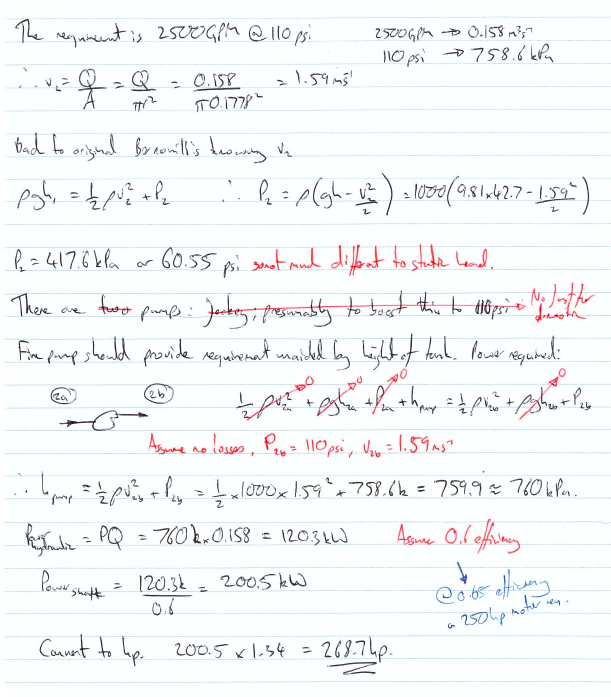
A couple of weeks ago, due to staff being on leave, I was given one of these to look at the pumps, seemingly alone. Having no idea what to do I browsed the drawings to work out what the issues might be. The project is a new 750,000 U.S. gallon water tower for domestic water and as a fire supply so my pavlovian response was Bernoullis!
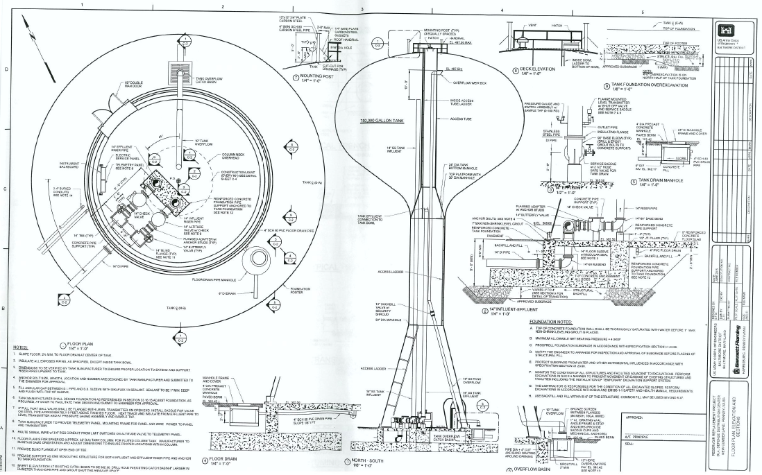

After checking the answer it seemed about right although there were no accompanying design calculations to the contract and drawings so I chalked up my first comment. The rest of the checking passed with less excitement. There were a few clauses that had been missed from the contract, some ill thought out processes and demolition elements missing from the drawings. It seems a common theme though that construction division give the most comments, usually about build ability and, as discussed in the past, what is actually existing at the site.
So what have I learnt:
Hopefully I’ve done Bernoulli’s right; simplify the problem and sketches work.
Designers, it appears, live in a magic construction dreamland and it is always the same build ability issues that are picked up. By using traditional contracts USACE does assume a lot off risk and pays handsomely for the privilege if elements aren’t caught by the construction team prior to tendering. Having recently moved into dreamland, albeit part time at present, the fine detail is easy to forget.
And as ever, time spent on recce…
Oz PCH – Electromagnetic Compatibility Concerns.
Introduction
Within Fredon’s (mechanical installation subcontractor) scope of works, one element is the mech-elec installation works associated with Variable Speed Drives (VSDs) site-wide. After a quality review, conducted by NDY (design consultants), of the standard of installation of completed works, a number of defects were found that were felt didn’t comply in accordance with the mechanical quality specification; of note was the VSD controller cable installation. These were communicated to JHG via a Consultant’s Advice Notice (CAN), which is routine practice.
Fredon did nothing to rectify the defects relating to the VSD cable and so JHG issued an Event Notification. This consisted of a Non-Compliance Report (NCR), raised on JHG’s internal quality management system. This has significant commercial implications for the subcontractor if not resolved in a timely manner.
Issue
The NCR stated that Fredon had not complied with the mechanical specification as the current installation did not include Electromagnetic Compatibility (EMC) glands amongst other issues. The NCR also stated that any installation works completed to-date must be removed and replaced with a fully compliant installation as per the project specification.
Fredon responded as required and provided explanation, aided by technical analysis from their electrical works subcontractor, Electromaster, for their reasoning behind their actions.
They confirmed that whilst they had installed an alternative to the specification, in all cases they meet the fundamental design intent, and in some cases have improved on it.
After a number of meetings NDY stated that whilst it was noted that some aspects of the installation may not comply with the literal wording of the specification, if Fredon were to demonstrate that the installation achieved the technical intent and complied with all associated relevant Standards, then it could be possible to consider the alternative, particularly that the manufacturer’s recommendations had been met.
Technical Background
Fredon and Electromaster put together a technical response on the issues raised in the NCR, in particular, for the EMC gland issue and stated that what they have installed also complies with Australian Standard AS 61800.3:2005 Adjustable speed electrical power drive systems – EMC requirements and specific test methods.
Why is electromagnetic shielding required?
In simple terms, all electrical equipment that has current running through it produces an electromagnetic field (EMF). This field requires shielding in order so that a build-up from multiple fields don’t interfere with other sensitive electrical equipment, especially the likes of those used for recording patient’s vital stats; in a hospital this accounts for a very large portion of electrical equipment and so electromagnetic shielding is vitally important. In addition, on certain equipment like VSDs where an inverter chops up the sinusoidal waveform, inverts it and splices it back together (through switching transistors on and off at a fast rate), this creates Radio Frequency (RF) energy which can be radiated and then coupled onto other equipment’s control and supply cables through either capacitive or inductive means. It can also be conducted to other equipment through a common impedance path such as an earth connection. So, it is even more important to shield cables that come out of VSDs.
How do we shield against it?
In this case we are talking about the motor power cable that runs from the VSD to a motor isolator switch and then to the motor itself. The mains electrical power cable to the VSD, although still carrying current, is not required to be shielded as it will be at 50 Hz and thus the same as other equipment and so doesn’t pose significant interference.
To shield cables a wire braided screen is used to surround the inner core conductor. This shielding impedes both the escape of any signal from the conductor and also prevents signals from being added to the core conductor – thus completely isolating the cable (see fig 1).
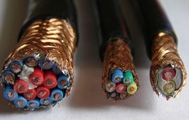
Figure 1. Typical Cable Wire Braided Shielding.
Issue Continued…
Electromaster included the manufacturer’s data sheet for the particular VSD supplied by Schneider which is used site wide; the ATV212W. They highlighted the relevant parts that confirm their installation complies with the standards. So, if NDY are content with this as mentioned then problem solved right? Not quite…
On closer inspection of Fredon and Electromaster’s technical response they highlighted the wrong VSD model and marked-up the installation guide for the ATV212H not the as-installed ATV212W.
The technical prove information was on page 52 of the installation guide, at the bottom of which it describes the ATV212W model and on the following page it clearly describes the correct cable arrangement and use of the EMC plate. Figure 2 shows the ATV212W and specifically states that the cable gland must be ordered separately as it’s not supplied with the VSD.

Figure 2. Manufacturer’s Installation Guide p.52.
Figure 3 shows the next page and highlights the need for a metal EMC gland and explains the mounting and connection required to correctly shield the cable and drive.
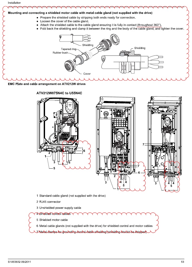
Figure 3. Manufacturer’s Installation Guide p.53.
Why was it installed incorrectly?
My view is that Electromaster have installed the VSD cables based on a combination of factors in order to save both installation time, which equals a labour cost saving, and capital costs. These are:
- Carrying out installations as per what they have previously done on other projects;
- Using standard plastic glands as these are significantly cheaper than metal EMC glands;
- Saving on labour time (approx. half) and thus reducing cost, by installing plastic glands over EMC glands, and;
- Possibly not having even read the design specification.
What is missing from their technical explanation of what they have installed is the actual termination of the motor cable into the VSD. An on-site inspection proved that they had indeed connected to the metal back plate in the VSD housing which is separately earthed, but the connection to the earth bolt was achieved by pulling the wire braided shielding round to one side and twisting it together to form what is referred to as a ‘pig-tail’ (bunched-up strands) and attached to the earth bolt (see fig 4).
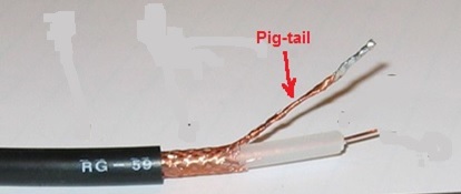
Figure 4. Cable Shielding Pig-tail – Bad Practice.
Figures 5 and 6 show the actual VSD installed by Schneider but wired by Electromaster. It can be seen in figure 6 the use of a standard plastic gland opposed to a metal EMC gland and also the shielding twisted into a pig-tail (heat shrinked in a green sheath) and connected to the ECM plate (earth). If the installation was left as it is then the pig-tail termination of the screening would mean that RF leakage could potentially escape through all the plastic glands seen in the bottom of the drive.
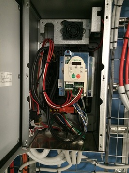
Figure 5. Schneider’s Installed VSD.
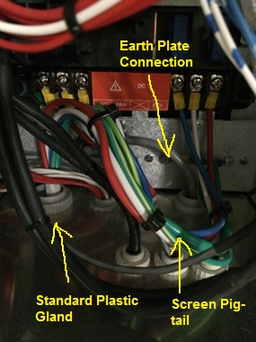
Figure 6. Electromaster’s Wiring of VSD Motor Cable.
The issue with what Electromaster has done is they haven’t completely screened the cable through 360 º, like the examples in figures 7 and 8 show.
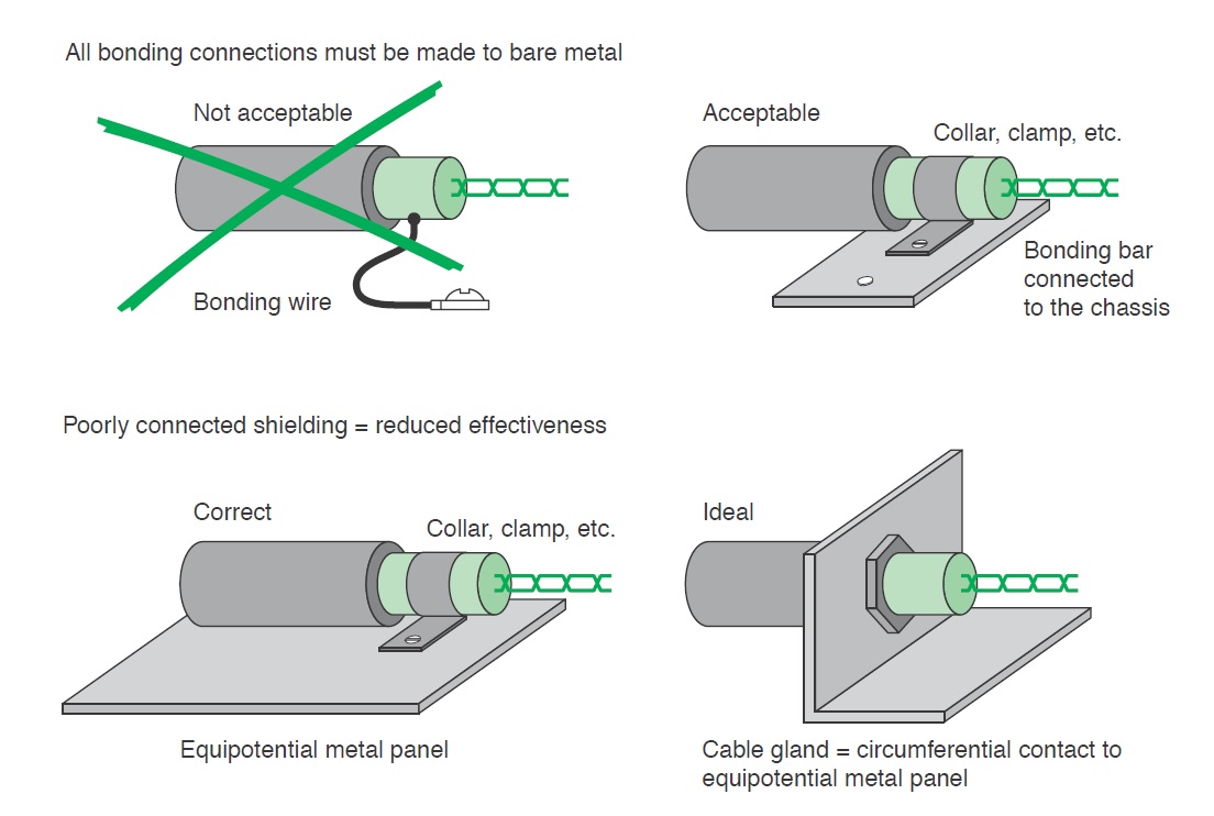
Figure 7. Schneider Electric Earth Connection of Shielding.
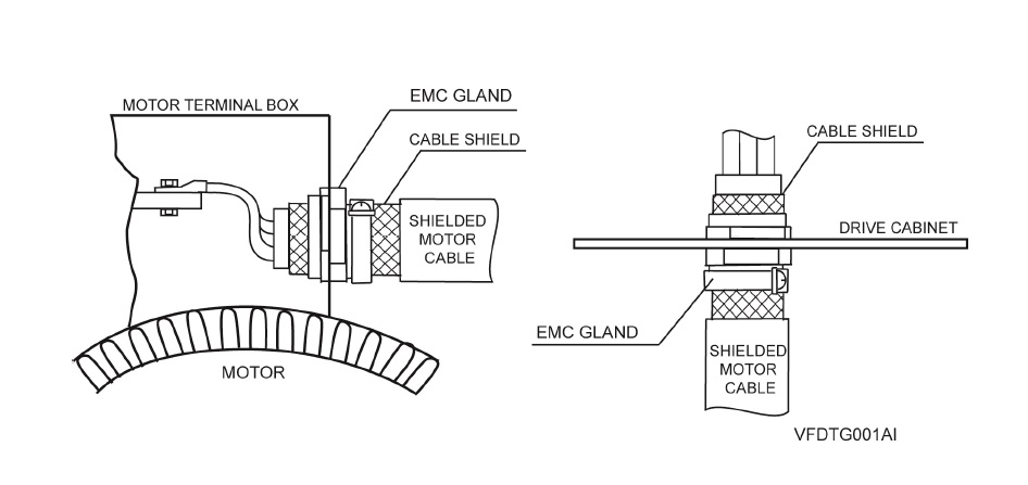
Figure 8. Power Electronics Earth Connection of Shielding.
The reason the lack of 360 º screening is such an issue is that when dealing with high-frequency electromagnetic radiation from an Alternating Current (AC) source it becomes distributed within the conductor where the current density is largest, near the surface of the conductor, and is known as the ‘skin effect’. The electric current flows mainly at the skin of the conductor which causes the effective resistance of the conductor to increase at higher frequencies. Therefore, RF leakage from any unshielded portion of cable can be quite high.
A quick Google search also reveals that pig-tail terminations for cable shielding is a big ‘no-no’. Even if the pig-tailed termination is inside a metal housed VSD (mini faraday cage) then technically the RF can’t escape as long as a metal gland is used. However, Electromaster used plastic glands and so this presents a clear path for any RF leakage.
The Design Specification Intent
The method behind using a metal EMC gland with a metal plate/VSD housing is that the VSD housing acts like a mini faraday cage with a separate earth cable running to ground. Where the cable enters the VSD it is secured in place by the EMC gland with the cable shielding pulled back on itself and the gland clamped around it making a 360º connection to both the shielding and the VSD housing.
The design specification explicitly says that:
Terminate screened power cables at each end in EMC glands to ensure circumferential connection of the screen to earth. Earth the screens of thermistor sensor and motor lockout cables at the converter cabinet utilising metal cable clamps for each cable fastened to an earth bar installed within the cabinet for the purpose or with EMC glands secured to an earthed gland plate externally to the cabinet, as specified by the manufacturer.
Motor isolators shall be 4-pole, key lockable mounted in a die cast alloy enclosure. The isolators shall switch the motor power and control circuits simultaneously. Cable entries shall be fitted with EMC cable glands and earth bushes suitable for the cable types connected. The earth bushes for each circuit shall be connected together with 6 mm2 cable to maintain continuity of screening of the power and control cables.
Resolution and Possible Fixes
One possible solution could have been to swap the plastic glands for metal ones as this could theoretically be adequate. However, Electromaster and Fredon would need to back-up this installation with technical proof of this which may be difficult as all reports on ‘best EMC installation practice for VSD’ state that the use of pig-tails is prohibited.
“A screened cable gland suitably designed and sized for the screened cable type used should be fitted at the motor end. Do not wind the screen into a “pigtail” and terminate under the earth terminal within the motor terminal box. Terminate the earth conductor(s) to the motor earth terminal(s) located inside the motor terminal box. When installing the SD700 directly on the wall (no additional enclosure) a screened cable gland suitably designed and sized for the screened cable type used should be fitted at the SD700 gland plate. Do not wind the screen into a “pigtail” and terminate under the earth terminal within the SD700 terminal box. Terminate the earth conductor(s) to theSD700 earth terminal(s) located inside the terminal box” (Power Electronics 2013).
Therefore, they need to comply with the design specification which is to use specific EMC glands.
So What?
There are approximately 400 VSDs site-wide with motor cables terminated incorrectly. These therefore must be re-worked as JHG have alluded to in their NCR. This has been confirmed by NDY and so Electromaster, via Fredon, must now conduct the re-work.
Costs
Based on the RS catalogue and list price, which clearly a subcontractor will get at trade but fine for comparison reasons.
Capital Costs
The capital costs of switching the glands alone would be in the region of $20k (£10k).
$25 per EMC gland x 800 (2 glands per VSD) = $20k
$1 per plastic gland x 800 (2 glands per VSD) = $800
A difference of $19,200.
Labour Costs
2 hrs per VSD at $65 – $80 per hour = $130 – $160 per VSD x 400 VSDs = $52k – $64k (£26k – £32k).
Total Costs
$72k – $84k (£36k – £42k).
Conclusion
From this example I have learnt a number of points:
- Subcontractors will, unless very diligent, usually default to conducting works how they have always done so on past projects.
- Due to point 1, subcontractor’s work must always be quality checked.
- Subcontractors will try and convince you that what they have done is in accordance with the specification. In providing technical evidence to back-up their installation, if an alternate method had been used, they will may well be proving only half the truth and purposefully omit defective practices.
- Due to point 3, subcontractor’s evidential explanations should always be scrutinised for accuracy.
- In an office block the leakage seen could probably be tolerated but the key issue in this project is that the building is a hospital and if there’s ever a place you don’t want to cause RF interference it’s in a hospital.
In Other News
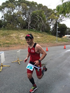
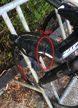
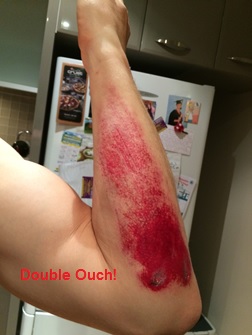
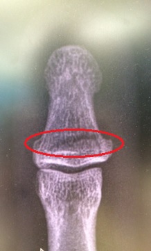
My Ironman (IM) trg has taken a bit of a hit. In a build-up half IM race I decided to trow myself off my bike but not forgetting to do my best superman impression before hitting the deck pretty hard. My initial annoyance was the damage to my bike; carbon fibre is costly! Although pretty battered, bruised and scratched (mainly to my pride), in good old Army fashion, I soldiered on finishing the remaining 20km of the bike leg and the 21km run. Post-race clean-up and a trip to A&E the next day confirmed I had actually broken my thumb; I did feel a fair amount of pain whilst trying to change gear – now I know why.
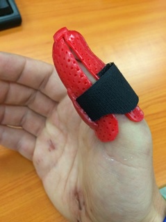
What impressed me most during my treatment was the thermoplastic thumb splint (available in a choice of colours) complete with water friendly Velcro securing strap, although I’ve already got some design mods in mind for version two. It means I can still compete in my next half IM trg race in 2 weeks’ time before the thumb is estimated to be fully healed 6 weeks from now.
Below are some pics…

Changing Seasons
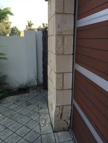
An interesting Chemical Anchor letter in the NCE, link below:
What is interesting about this is the warning which the author gives and the prevalence of these anchor systems on my site. In one case design starter bars were ‘RFI’d out’ of the design in preference for a drilled and epoxied system to be installed at a later time. The rationale being that leaving the starter bars out of the floor room my subsequent work, and was less of a safety issue.
Epoxied rebar to replace CMU starter bars
I had HILTI delivered training which supports the letter; there can be a huge loss of design strength in these systems if they are not installed properly and, by HILTI reckoning only 20% of anchors are properly installed. HOWEVER, these systems can be very effective. So what? If these are specified on your site, or indeed if you end up specifying them as a part of your design phase then just make sure that the tradesmen installing the systems have the correct qualifications and equipment otherwise, as the letter highlights, especially in safety critical applications you may ‘have dramas.’
Changing Seasons affecting Work
The cold weather is encroaching slowly but surely (a bit like my progress towards the finish line of a recent ten miler). This has highlighted a slight lapse in the PC’s QC process in-so-far as there is a cold weather plan for the placement of CMU at my central utility plant, but it is not being stuck to. On a recent cold snap the block had become too cold and the grout samples were not being taken by the specialised testing sub contractor at a representative time. Nor was there a QC rep on site to remediate the issue. As QA acting on behalf of the client I was required to step in; the simple fix being to stick the blocks in the sun for a while to heat gradually and use warm water in the cement mix to maintain the correct temperature (per the plan). I engaged with the QC manager to ensure that as the cold weather becomes more frequent there will be a QC rep on site at time of the key risk, in this case first thing in the morning when the very first blocks are being laid.
False Reporting
I conducted the latest pencil walk last week in conjunction with some of the other area representatives (M&E, architectural). There have been some discrepancies in the PC reporting, including the reporting of percentage completion of a scheduled activity which doesn’t tally with the expected remaining duration. It seems that it is easier to project the cost of an activity rather than its expected duration. At present activity percent complete is reported and agreed, and the remaining duration and accrued cost of the activity is calculated. For payment this is fine, because the payment estimates are fairly accurate but for remaining durations it is not working. This is leading to a false representation of the project completion, which is what the client, hence USACE is interested in. In some cases (my CMU for example) the original duration was estimated at 15 days, based on a 5 day calendar. It has been going on for almost 2 months now. It is around 65% complete, which means that the computer thinks it has around 5 days left to complete before the successor activity can proceed… In actual fact the successor activity can’t proceed for, in my opinion, another 15 days. This will eat into the activity float. Not a problem for my CMU, which has oodles of it, however if an activity with less, or no float has this issues then the critical path might be affected. The PC now has to walk through and agree actual remaining durations with USACE on future pencil walks to ensure the accuracy of reporting. This will help more accurately reflect the contract completion date. Below is an example of the issue – the overhead HVAC has an original duration of 40 days, is 25% complete yet has an anticipated actual remaining duration of 60 days.
Example from pencil walk
Note for Phase 1s
As you’ll know from visiting my site yesterday I have just one week left on site. Damo and Olly a little more, Dan and Daz a little more again. So if you want examples of things we’ve seen to put what you’re learning into real life context, photos of stuff we’re doing, or even just to ask about how we find our attachment locations, now is the time to ask. I am very happy to provide photos and answers and I’m sure the other lads are too. But get in fast as time is short!
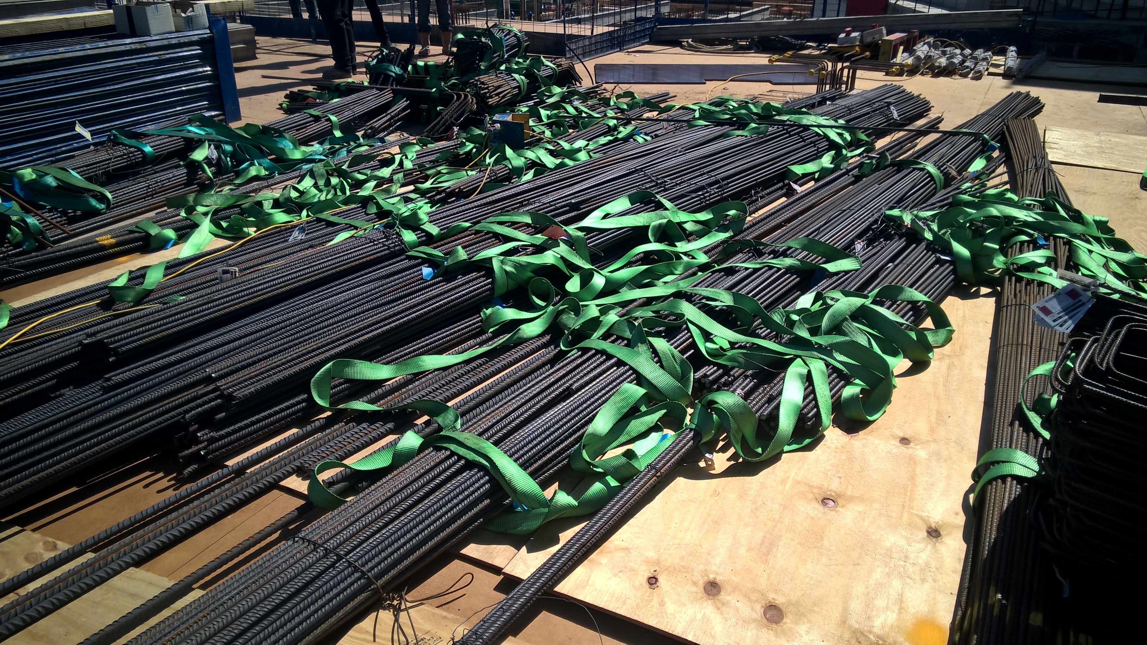
Here is a picture of the steel as it gets delivered as a starter (requested by Richard):