Archive
Two Fifty One – Curing Methods
Two Fifty One – Curing Methods
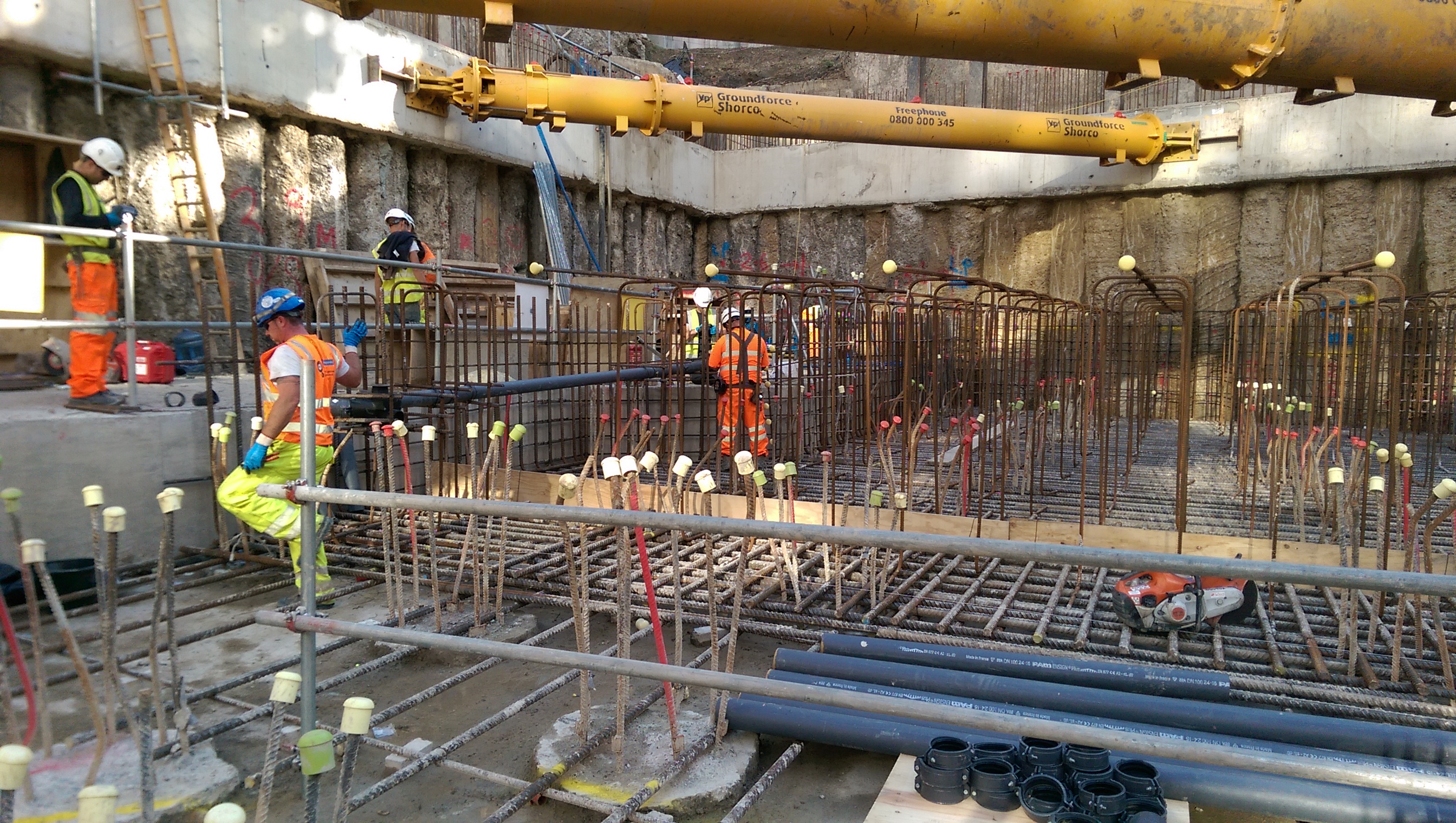
On Wednesday we did our first large(ish) concrete pour (225m3). This was for the basement raft and 2 pile caps. The aim was to fill the 2.1m deep raft (large pile cap) to underside of slab which will be formed across the entire site (450mm thick, to be cast in waterproof concrete). The setup was a mobile pump at the end of our pit lane which involved having concrete wagons back onto the pump. Luckily the front of the vehicle was far enough away from the road to avoid any road traffic accidents.
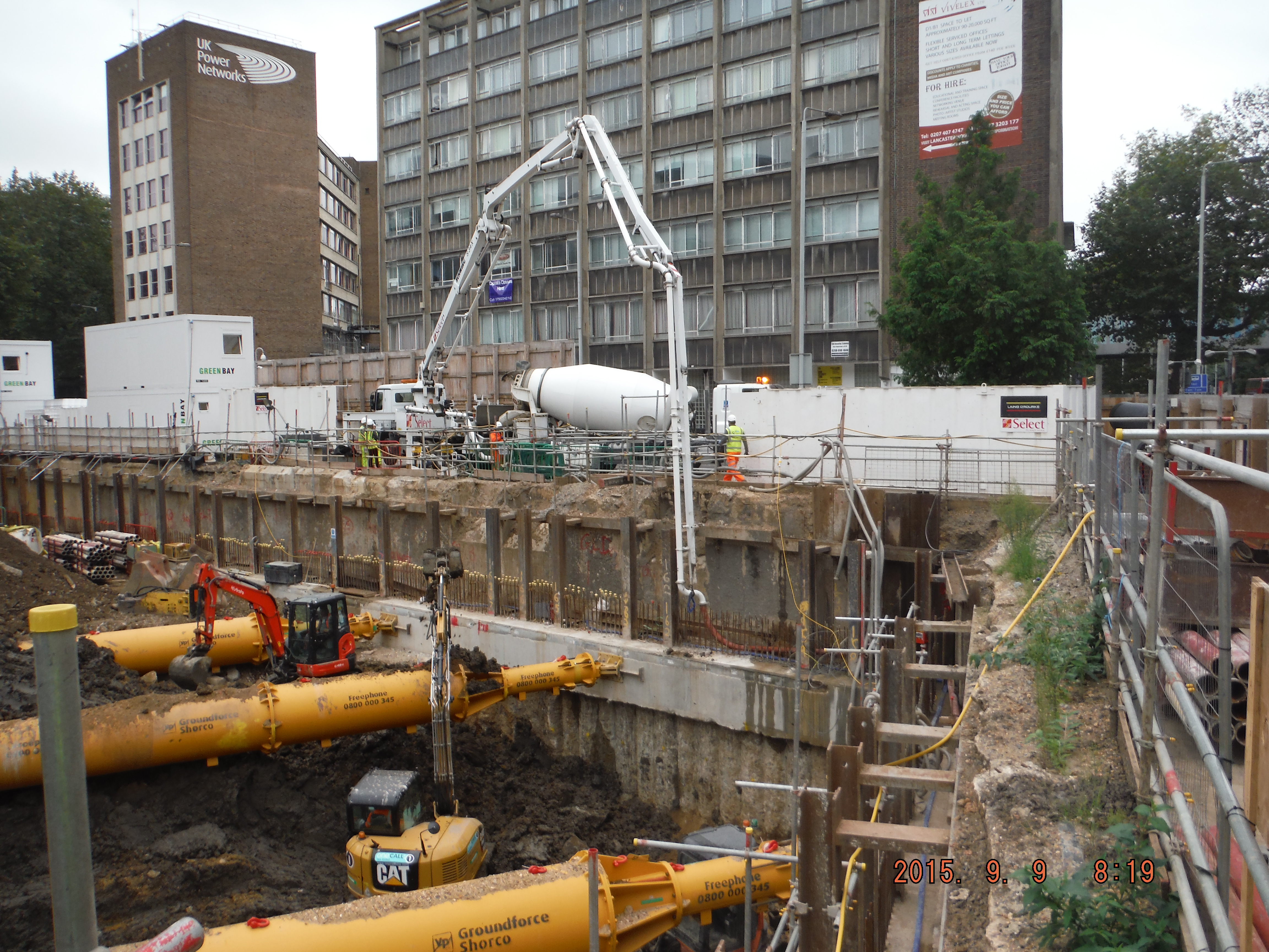
Pump positioned within the site, concrete wagons backing onto it, just into site. The pipe line then ran around along the capping beam and down to the pour location.
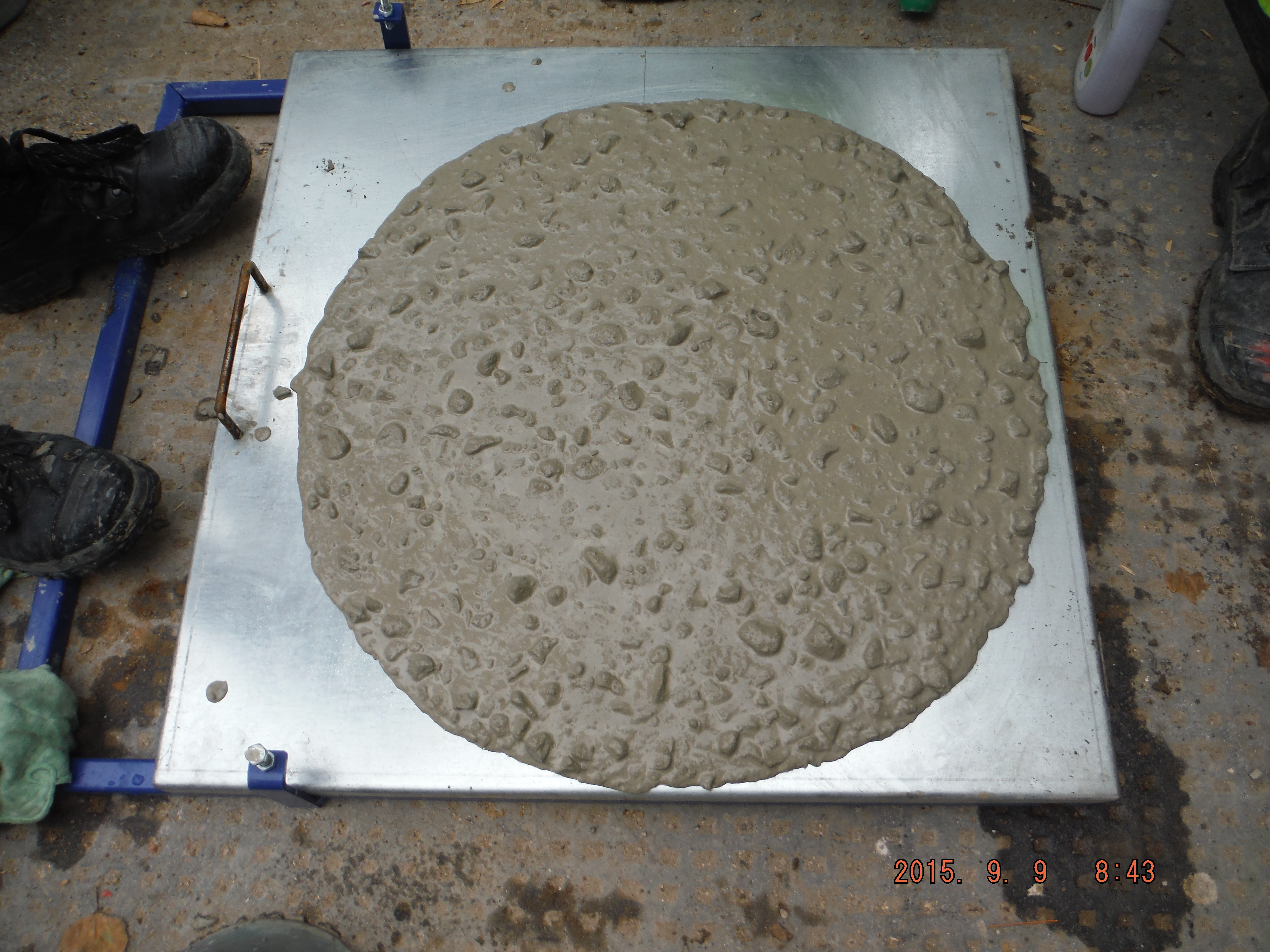
F5 consistence – therefore flow table tests. Interestingly the test was repeated after 4hours and it achieved just a 20mm lower radius.
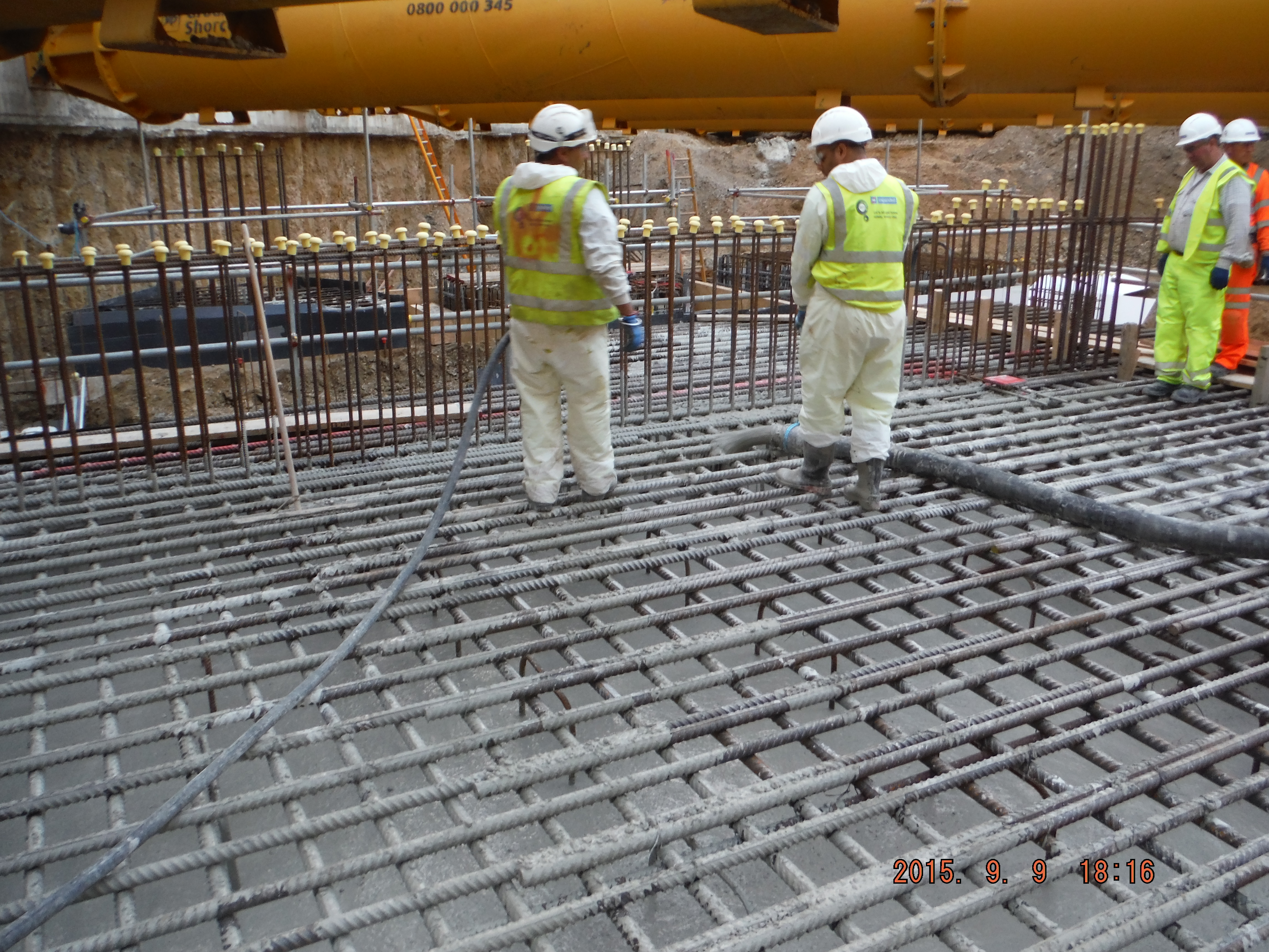
Pour was to underside of slab level, which is about 400mm below the height of the reinforcement shown. Before the concrete is fully cured it will need to be removed from the rebar.
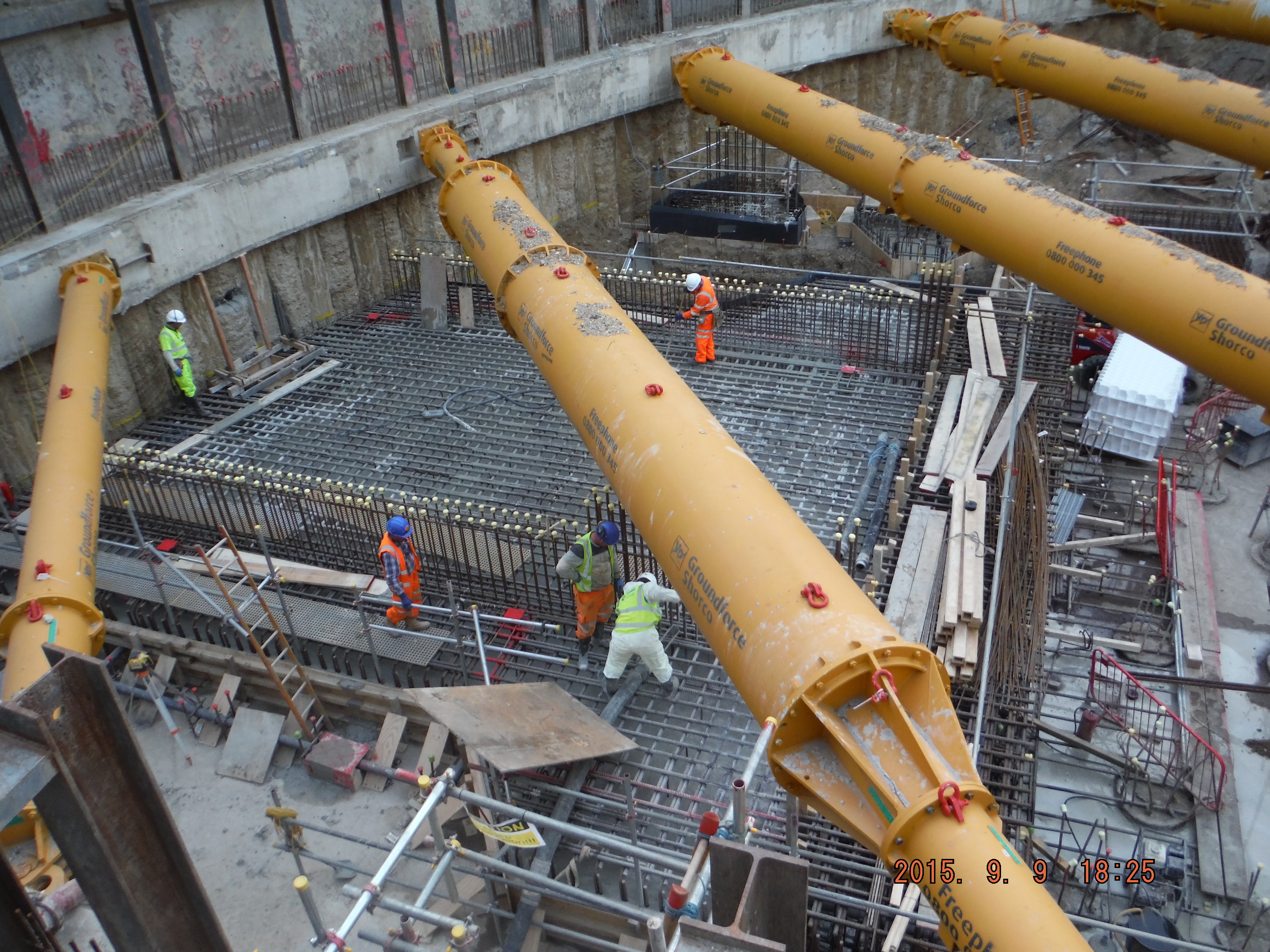
Overview of raft pour – see wall starters to negotiate when curing.
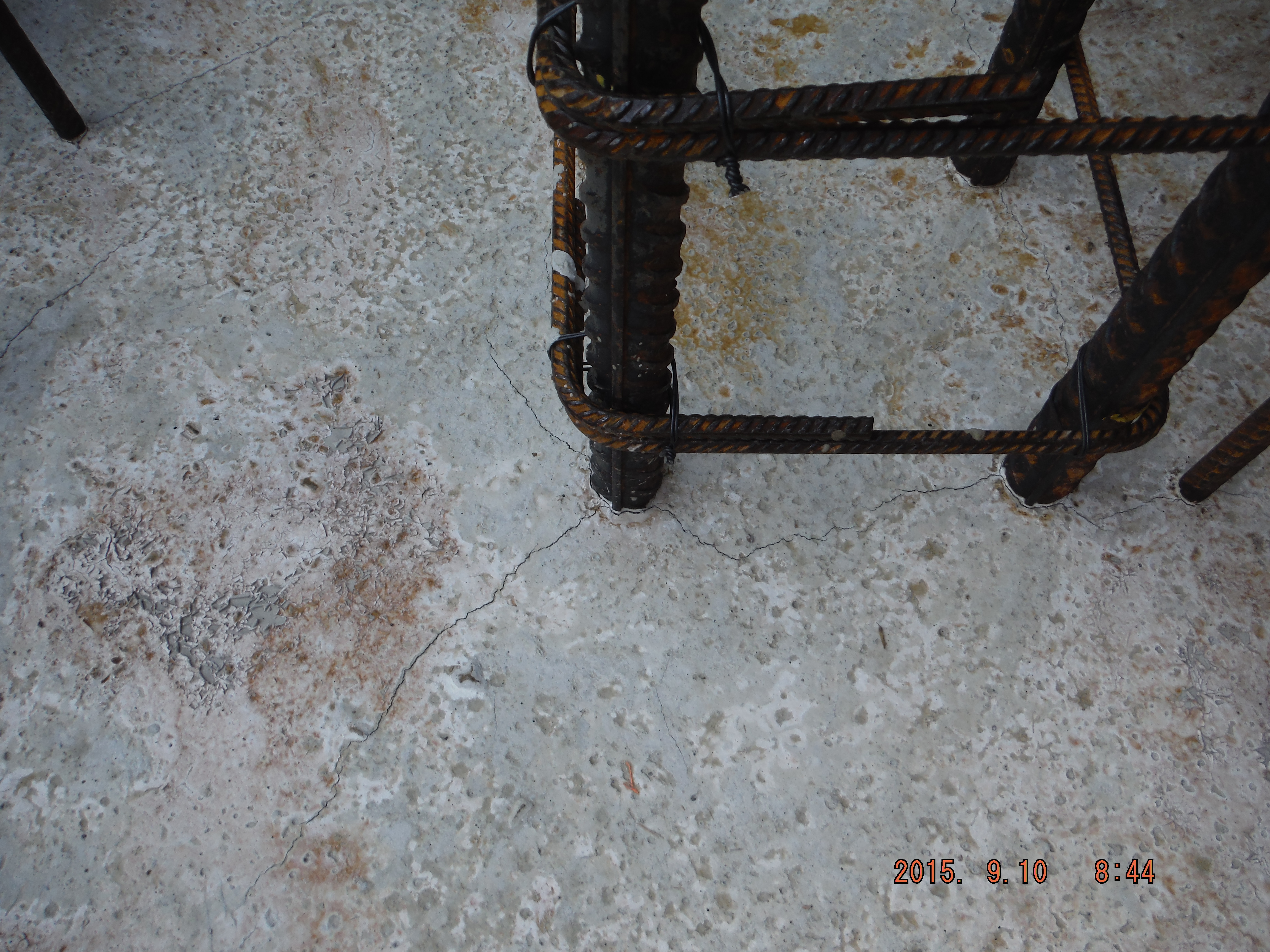
Next day thermal shrinkage cracks. The hope is that when the slab is cast on top it will have fewer cracks because it is only 450mm. Additionally, it will contain a waterproofing additive to prevent water ingress.
Quality Assurance
The quality assurance process involved taking flow tests of the wagons every 5 vehicles and cubes every 50m3. Each delivery was checked for the mix and the details recorded on the pour history sheet (mix, batch times, location of where the concrete ended up). The idea being that should a random concrete wagon arrive at our site we would spot it. Amusingly, one of our wagons ended up somewhere else who were not using quite such a stringent checking process!
There was a drained cavity sump within the pour which had to be in waterproof concrete and so this was poured using a hyrib stop end with the last pour of the day/night.
When we come to do the slab the final finish will be an epoxy floor coating, the concrete slab will be shot blasted to give it grip because it is a car park. Coming to our part in this plan, the slab will need to be cured. There are two common methods:
Polythene and spray on.
Polythene
Advantages: Quick to apply, logistically not too difficult to put in place (polythene rolls are not heavy), 100% moisture barrier (assuming all sides are fastened down),
Disadvantages: Protrusions such as wall starters, polythene marking the slab, mitigated by keeping the polythene sheets as flat as possible, and tearing is likely.
Curing agent
Advantages: Pretty cheap and not difficult to apply.
Disadvantages: It is time consuming to apply, a sprayer is needed, ensuring complete coverage is difficult because it is not easy to see where it is applied. It is not an impermeable membrane so there will be some evaporation.
Recommendations
Polythene, if applied correctly is likely to give a better method of curing because of the 100% moisture barrier. The difficulties in our case of fitting it around wall starter bars can probably be overcome by fastening it either side of the protrusion.
Anyone any experience/views on the matter? What do they do in the US/ Australia for curing slabs?
The Lost Thome
Apologies its been so long since I lost posted, you poor people! I found this post drafted and ready, from before I went on summer leave. I must have neglected to actually put it on the site in the rush to get out of the door.
The Chiller Plant is nearing completion (structurally) and the steel sub contractor building it is starting to prepare for its next large steel erection task on site. Construction of the Chiller plant has been somewhat of a rehearsal for the construction of a large steel truss roof, architecturally designed to be the crown jewel of not just the JOC project but also an icon of the campus. Colloquially known as the ‘Bridge of the Enterprise’ because of its elliptical shape, it will be more of a challenge than the chiller plant. So far it has been high on peoples agenda because of the proximity to an adjacent site which will make de-confliction of crane picks impossible. Cue the start of night work. This is an interesting issue in itself because the adjacent project is c. 1 year behind schedule and so the impossible deconfliction issue is not of our making. In the ‘real world’ I am sure that there would be much less accommodation made for the late contractor and numerous claims for LDs and delays etc. However USACE is required to manage the programme and so the success of both projects must be considered.
We also had to throw the erection plan back to the PC this week. I was part of the team reviewing it and gave general input about compliance to the USACE health and safety manual (EM-385) as well as being the ‘Structural Lead’ for the JOC, whose real Structural Lead was in Hospital with his wife who had broken her fingers playing American Football. The plan seemed OK on the face of it; containing all elements required by EM-385 (the USACE H&S document). These include details of site location, material deliveries, staging and storage, co-ordination with other construction, crane type and capacity, lifting methods, pick path, site preparation descriptions, stability of the erection, certifications …etc. The main bit of concern to me was the actual description of the steel erection activities. Fairly key then.
The subbie had done a brilliant job of communicating the first stages of the job on a simple on pager with different colours corresponding to different stages of the phase. It highlighted what the safe ‘walk away’ point was, was easy to read and clear (PSB)
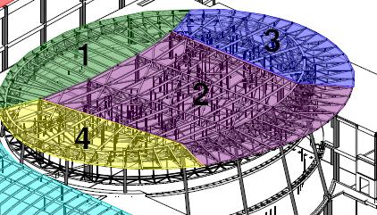
Colour Coded – showing sequences
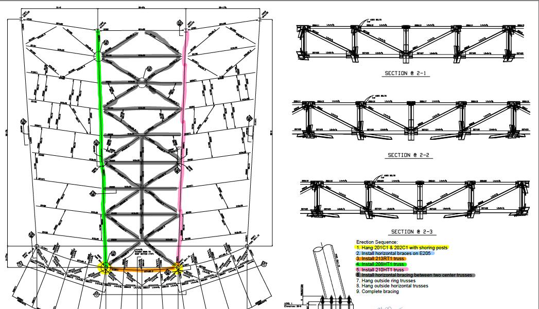
One of the sequences in detail
Unfortunately –
that’s where it stopped. I looked to the narrative for help, but it kept referencing other pages of the document, which was not paginated. It left me filling in the next stages based on assumptions and wooly assertions based on my knowledge of the project and a narrative that said ‘repeat steps 3 – 7’. To my mind totally inadequate. The erection plan itself should be a simple document that you could give to pretty much anybody who should then be able to look through and clearly identify at what stage the construction is at, what’s coming next and at what stage it is safe to terminate construction such that what’s already been built won’t fall down. If the subbie had simply done away with the narrative and continued with ten one-pagers I think the plan would have been much better.
So what’s the point of this bit of the post? 2 things: In the army we are gently encouraged to communicate on paper in set formats. This helps, and it’s a skill/requirement we perhaps take for granted. We can add a lot of value to a site / task / project through non-technical skills like these. But secondly the most complex of tasks can be communicated through the use of some simple, well thought out sketches. In this case, it would have been a lot better to have done so.
The Oil & Gas Industry
Following an amount of chat on whatsapp regarding shares and in particular oil & gas shares (and following Jim’s comment on my last blog) I thought it might be worth writing a small blog to let you know where the industry is at the moment, as it seems like the construction industry is ‘steady away’ while the oil & gas industry is on its arse!
The oil & Gas Industry – Where are we?
The industry is not in a good place right now and of course it all relates to the price of oil. Demand has decreased whilst supply has increased leading to significant problems for all involved, especially for those who have the highest extraction costs. Different people will have different views as to the cause of the current trough, but can be summarised as follows;
- Increase in production in the USA due to onshore fracking.
- Canada & Iraqi oil production and exports are rising year after year.
- OPEC declined to cut production.
- Decrease in demand from the far east.
- Conspiracy theory that the Saudis & USA want to hurt Russia & Iran.
- Conspiracy theory that OPEC want to drive the new USA fracking market into the ground (excused the pun).
To make matters worse, in order counter the fall, many producers have increased production.
The following is a history of Crude Oil prices since 2000 showing a significant drop in 2008, due to a combination of an oil drilling ban being lifted by the USA, easing of tensions between the US and Iran, a stronger US dollar and the likely decline in European demand. It also shows the most recent drop which is struggling to recover in the same way the 2008 drop did.

Price of Crude since 2000
So what?
So, unless it costs you less that the price of crude to extract the hydrocarbons, you are making a loss. Let me put it into context. The cost to extract from the North Sea is somewhere between $20 and $60 /bbl depending on the operator, type and location of reservoir etc. Each producer would typically assume an extra amount per bbl of say $10-20/ bbl as an investment cost for future improvements/developments etc. So unless you are at the far left of this scale then you are going to make minimal profit, if at all. Currently BP (North Sea) is in the bottom third.
What is BP North Sea doing?
For the last 12 months or so, BP have been on a big drive to reduce operating costs and try to get out of the ‘bottom third’. BP expect oil prices to remain low for some time to come and are taking quite a pessimistic view on this. In order to make the North Sea more profitable, BP have been looking at the following;
– Cutting staffing costs, circa 200 in the last year (circa 10%)
– Cutting back on OPEX & CAPEX budgets
– Prioritising projects that add the most valve for the business
– Delaying projects or extending projects to share cost with following year’s budget
– Increasing production to lower average cost of production
– Simplification across the business in order to reduce costs
To answer Jim’s question – Yes there is a reduction in our projects, but also a drop in manning, so still busy! The less important projects have been pushed to the right with the big ‘increase in production’ projects still moving forward.
The future
The price of oil is expected to remain low for some time, unless something significant happens that reduces global production. BP is continuing its drive to improve efficiency and simplicity and increase production, and is continuing to invest in existing plant and future developments. It has been working and BP is creeping towards the middle third.
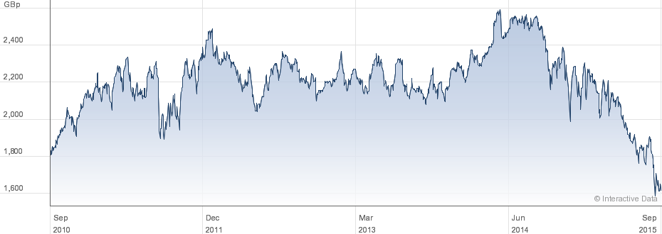
The above information is not a recommendation to buy/sell shares, and is just the view, in part, of the author. The value of investments can go down in value as well as up, so you may get back less than what you invest. I certainly would listen to me since the BP shares I bought in Jun have dropped 30%!!

BP share price over the last 5 years
Shell share price over the last 5 years
Oz PCH – Ductwork Leakage Pressure Testing.
Introduction
As part of the commissioning of the Air-Handling Units (AHUs) one test is to ensure any air leakage, which results in loss of pressure, is kept to within allowable maximums. This blog briefly discusses a leakage test I witnessed for one of the High-Efficiency Particulate Arrestance/Air (HEPA) filters in the operating theatre department.
In the application of theatres the HEPA filter is part of the laminar flow hood situated directly over an operating table. Here the filter’s minimum resistance (pressure drop) to airflow is specified at around 300 – 400 Pa at 370 l/s flow rate. The effect felt by the patient undergoing an operation is one of a soft blanket of very clean air.
HEPA Filter Function
HEPA is a standard and not a type per se, set by the United States Department of Energy (DOE) and is only awarded to filters that satisfy certain standards of efficiency. To qualify as HEPA an air filter must remove 99.97% of particles that are of 0.3 micrometers (µm) in diameter.
HEPA standard filters are composed of a thin mat of randomly arranged fibres. Fibres are typically between 0.5 to 2.0 µm and made of fiberglass. The air space between fibres is typically > 0.3 µm and the common assumption that fibres smaller in diameter can pass through (like a sieve) is not true. HEPA filters are designed to target much smaller particles which get trapped, by sticking to the fibres, through the following mechanisms:
- Interception. Where particles following a line of flow in the air stream come within one radius of a fibre and adhere to it.
- Impaction. Where larger particles are unable to avoid fibres by following the curving contours of the air stream and are forced to embed in one of them directly; this effect increases with diminishing fibre separation and higher air flow velocity.
- Diffusion. An enhancing mechanism that is a result of the collision with gas molecules by the smallest particles, especially those < 0.1 µm in diameter, which are thereby impeded and delayed in their path through the filter and raises the probability that a particle will be stopped by either of the two mechanisms above; this mechanism becomes dominant at lower air flow velocities.
Figure 1 shows a typical filter layout/construction with pictorial explanation of the three types of filtration; interception, impact and diffusion.
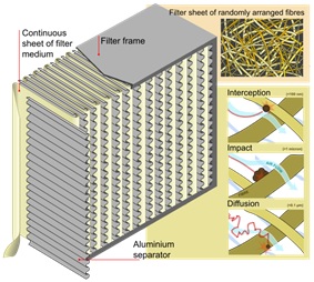
Figure 1. HEPA Filter Layout/Construction.
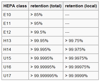
Figure 2. HEPA Filter Classification.
Figure 3 shows the laminar hood above the operating table in the operating theatre.
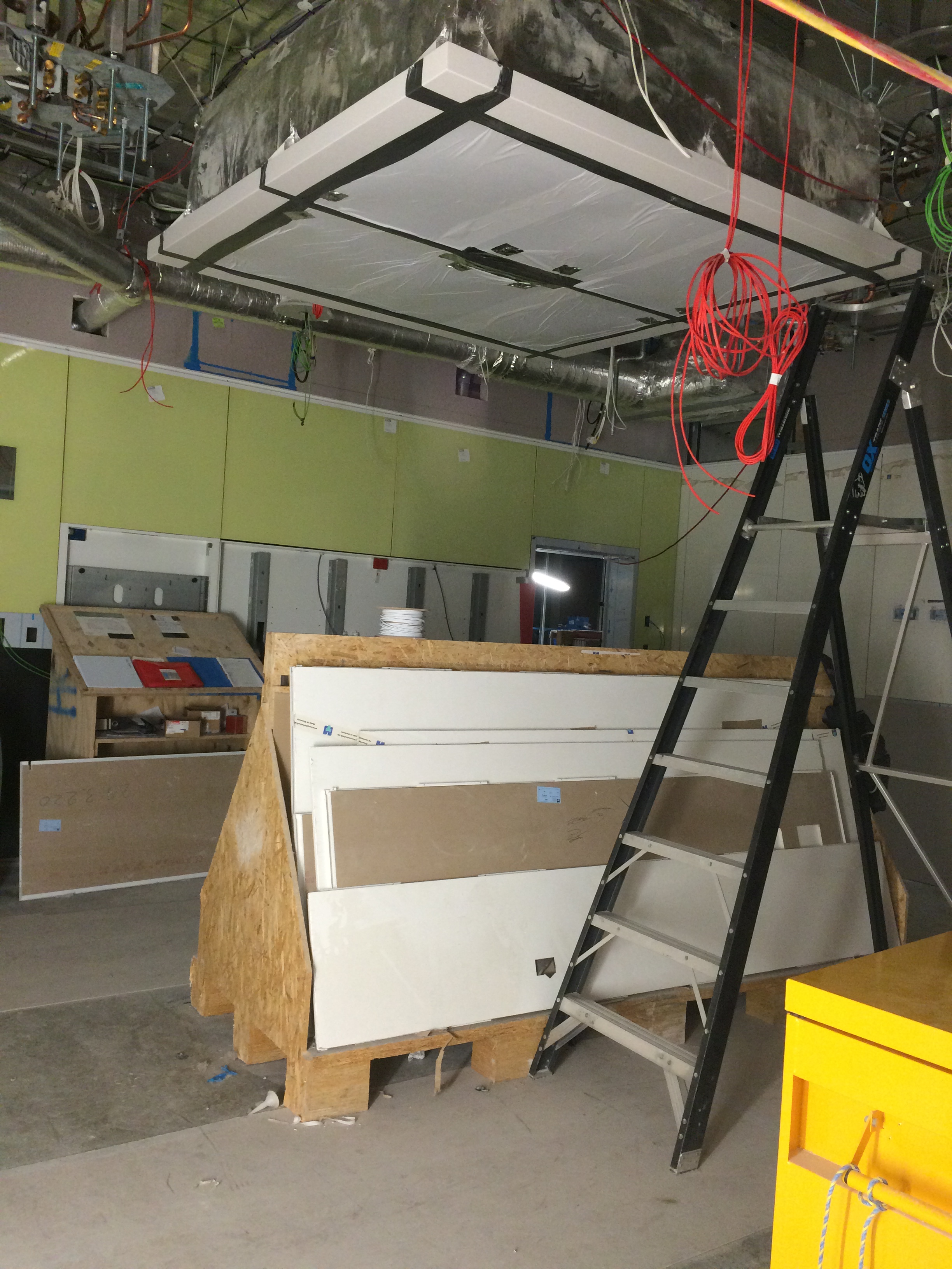
Figure 3. Laminar Flow Hood in Operating Theatre.
Fredon test to AS 4254 – Ductwork for Air-Handling in Buildings, which stipulates:
2.2.4 Air leakage
Duct systems with a capacity of 3000 L/s or greater shall be tested for air leakage at a static pressure of a minimum of 1.25 times the calculated design operating pressure in the tested duct section. Leakage shall not exceed 5% of the design air quantity for the duct system.
The systems in theatres are not greater than 3000 l/s of air so there was no actual requirement to test but Fredon conducted them regardless.
Leakage Test
As per the AS, 1.25 x our design pressure gives just below 750 Pa. The design pressure being the pressure produced by the fan plus any losses created by the Fan Coil Units/filters in the AHU (about 150 – 200 Pa) totalling around 600 Pa. The test achieved this and further more we were assured by Fredon that under normal operating conditions the duct would not reach this pressure.
The ductwork in question was one of four terminals branching off a single AHU (see fig 4). Each terminal has a flow rate of 370 l/s x 4 = 1480 l/s. Testing for a maximum of 5% leakage at a pressure of 750 Pa gives 5% of 1480 l/s = 74 l/s.
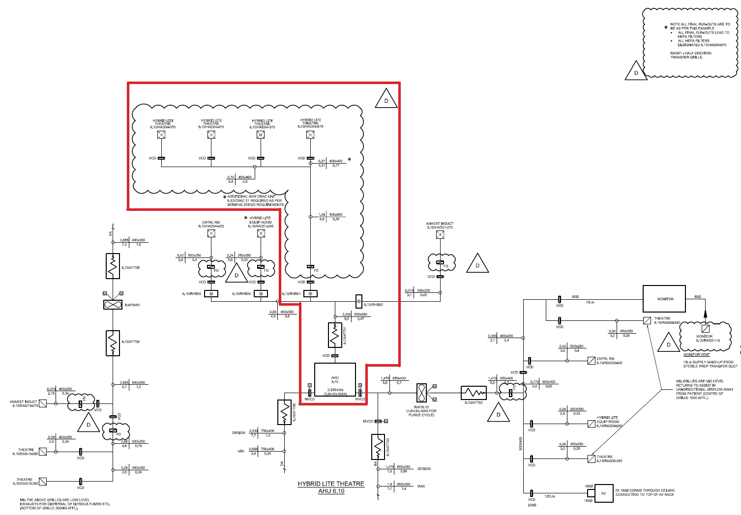
Figure 4. Schematic of AHU 6.10 showing 4 x Theatre Laminar Flow Hoods.

Figure 5. Leakage Test Sealing Plate and Hose.
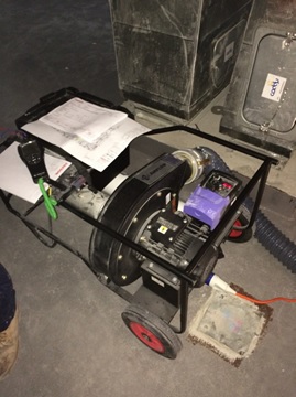
Figure 6. Leakage Test Rig.
Potential Issue
There was a potential issue raised as NDY, design consultant, stipulated in their design specification that ductwork should be tested to CIBSE standards – which refers to Heating and Ventilating Contractors’ Association (HVCA) DW/143 Ductwork Leakage Testing. Here it states that the system leakage loss for Class B medium pressure ductwork, under operating conditions, should not exceed 3% of the operating pressure.
Therefore, 3 % of 1480 l/s = 44.4 l/s.
So, 13 l/s is still well within the CIBSE/HVCA limits.
There was also a further potential issue in that the client may have wanted the test pressure to be the maximum for that class of ductwork, which is 1000 Pa operating pressure. As Fredon were adamant that the system would never operate above 750 Pa they were reluctant to test to this higher pressure.
In order to ascertain if the leakage would still be within the maximum limits due to the increased pressure a calculation could be conducted. There is no precise formula but it is generally accepted that leakage will increase in proportion to pressure to the power of 0.65 (HVCA 2000). This is due to leakage from ductwork occurring at the joints and seams and is therefore proportional to the total surface area of the ductwork in the system.
Therefore:
(1000/750)^0.65 = 1.2056.
1.2056 x 13 l/s = 15.76 l/s (for 1000 Pa). So, 15.76 l/s of 1480 l/s = 1.06% – still well within the 3% limit.
As it turned out the client did not request the 1000 Pa test pressure and so the calculation was not needed but at least it enabled me to investigate the issue.
Remaining Leakage Testing
Once all HEPA filters have been tested, from the plantroom through the slab to the hoods, and passed the ceilings can be closed and then the remaining ductwork from the plantroom slab back to the AHUs can be tested. This approach ensure concurrent activity for other trade contractors and by splitting up the ductwork Fredon can more easily identify and locate if an area of ductwork fails testing.
In Other News
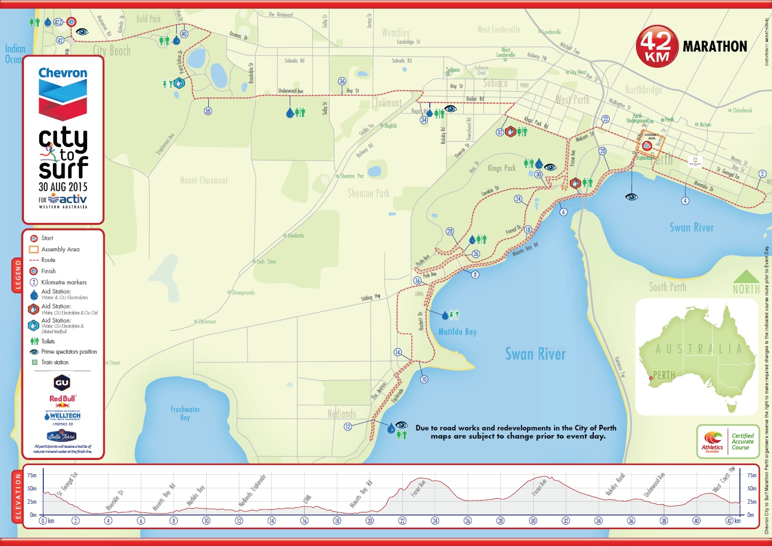
I completed the annual City 2 Surf Marathon at the weekend, my first standalone marathon, in 3hrs 30mins; pretty chuffed and it took till mid-week before I could properly walk, pain-free, up and down stairs!


Site Two Fifty One – Environmental Problems
Site Two Fifty One – Environmental Problems
During the removal of spoil from Two Fifty One to enable the installation the Groundforce props some of the lorries of muck were rejected from the tip because they smelt of diesel. I had no record of a diesel spillage on site so it all seemed strange. The loads had to be returned to site because the tip was refusing to take them and the carrier (Erith) were not able to dispose of them. Typically as the excavation progresses it becomes harder to separate/segregate anything. Therefore having excavated material returned to site is somewhat of a problem.
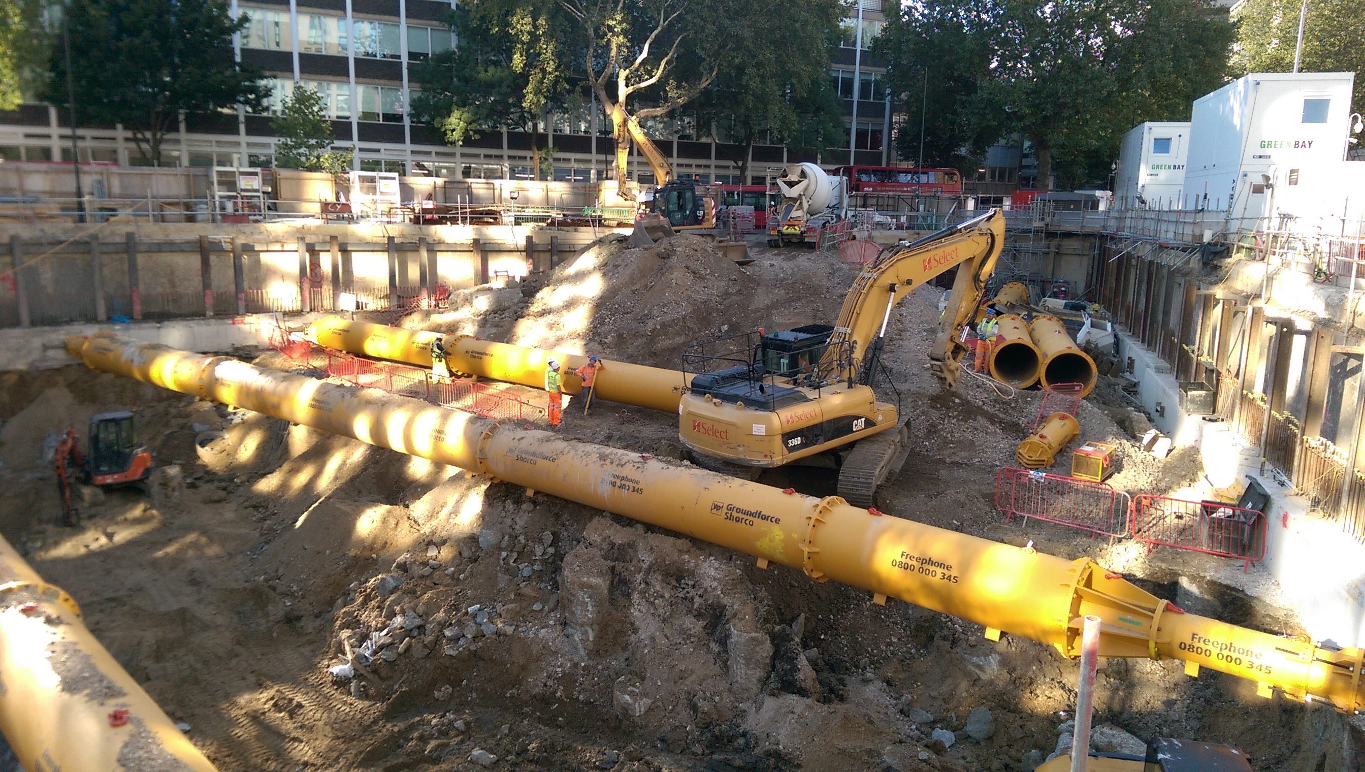
Contaminated material being stored left of the ramp access into site.
On further inspection of the area the muck was being excavated from it was identified that some of the sand and gravels had turned grey. I.e. it contains diesel.

The photos show the grey streak in the sand and gravel showing the diesel contaminated ground.
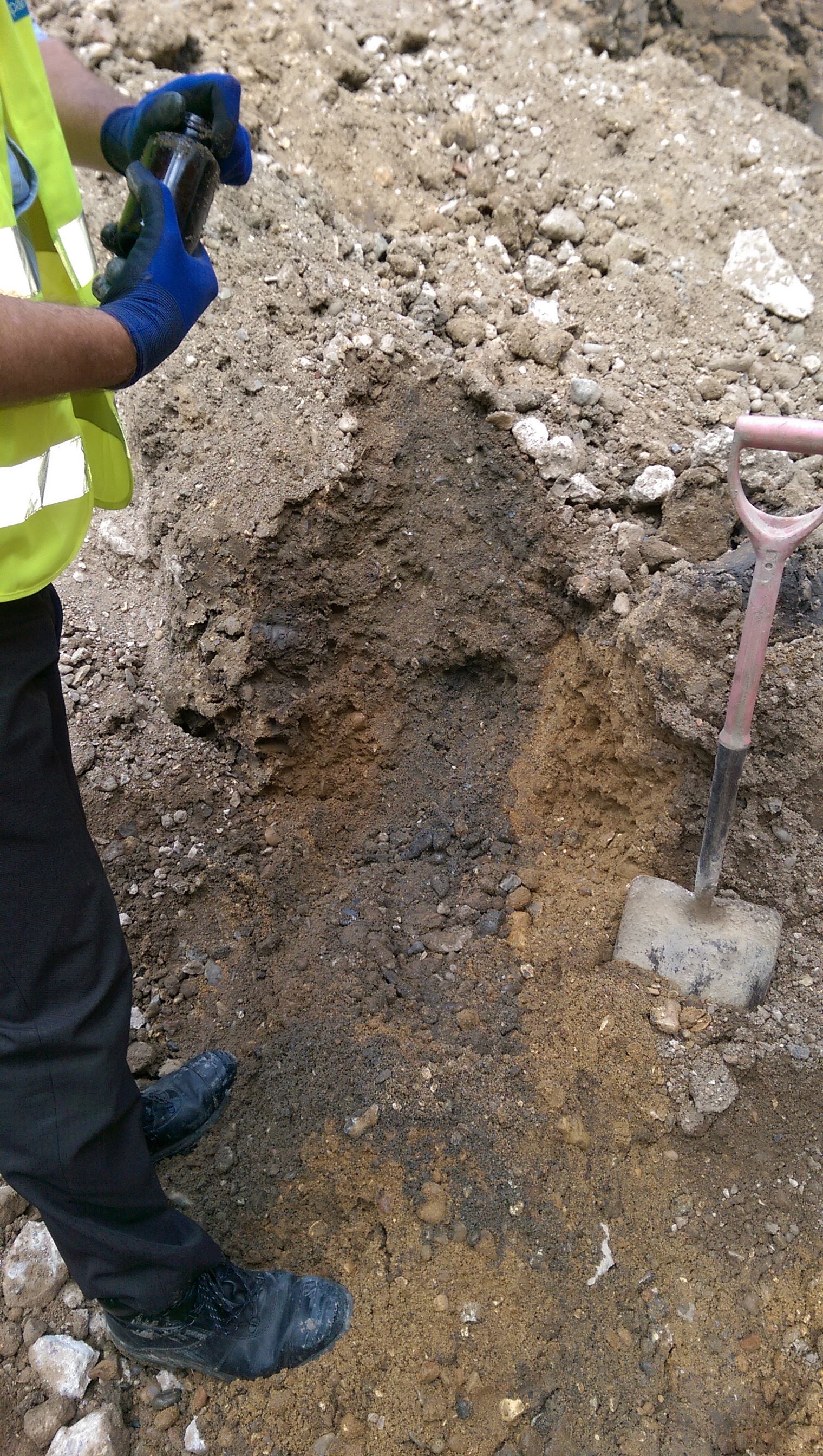
Aside from the fact that the majority of the area had been excavated and loaded onto tippers (albeit to then be returned to site) it was clear where some of the more affected areas were which should help reduce the spread of contamination.
So what?
The extent of the problem is just getting started (no environmental agency involvement yet) and as it has happened and now stopped, typical actions – such as using a spill kit/isolating the source are redundant. Therefore I have highlighted some of the post incident considerations we are currently going through.
- Stop sending muck away from the site (significant impact on programme as the key task is to remove muck at this stage).
- Identify what the contamination is. Initially, this will be done by using a Photo Ionization Device – this gives a rough and ready level of volatile organic compounds in the sample. Below 50 parts per million is apparently acceptable. You don’t need much diesel to make things smell of diesel so I am hoping that is the case…
- Record/report the incident, brief the site team on the importance of reporting spillages.
- Once we know the extent and type of the contamination the loads can be removed. Worst case the muck will be removed as hazardous waste at £1700 per load which comes with permits to move hazardous material. We are paying about £200 at present so that would have significant commercial implications!
- Attempt to keep to schedule with a mini-mount Everest forming in the corner of the site!
More widely here is a brief update on drainage and reinforcement installation.
Drainage.
We have just started to install below ground drainage in the Basement Level 2 raft slab. We are using the Saint Gobain timesaver inspection chambers and Ensign pipes. For future reference, Ensign is a significantly lighter product, more easily moved/handled and costs much less (we have made a circa £30K saving by requesting to use the lighter system).
The drainage is being installed within the area between the bottom and top mats of reinforcement.
What I wish I’d known:
- Testing methods – something about bungs, and air bags. More to follow when I understand what that is.
- That a foul gully run cannot rapidly change gradient in a run because the solids will separate out.
Basement Raft.
The 2.1m deep raft foundation is currently being constructed. It is quite an impressive site seeing 40mm, 12m long bars being positioned by hand.
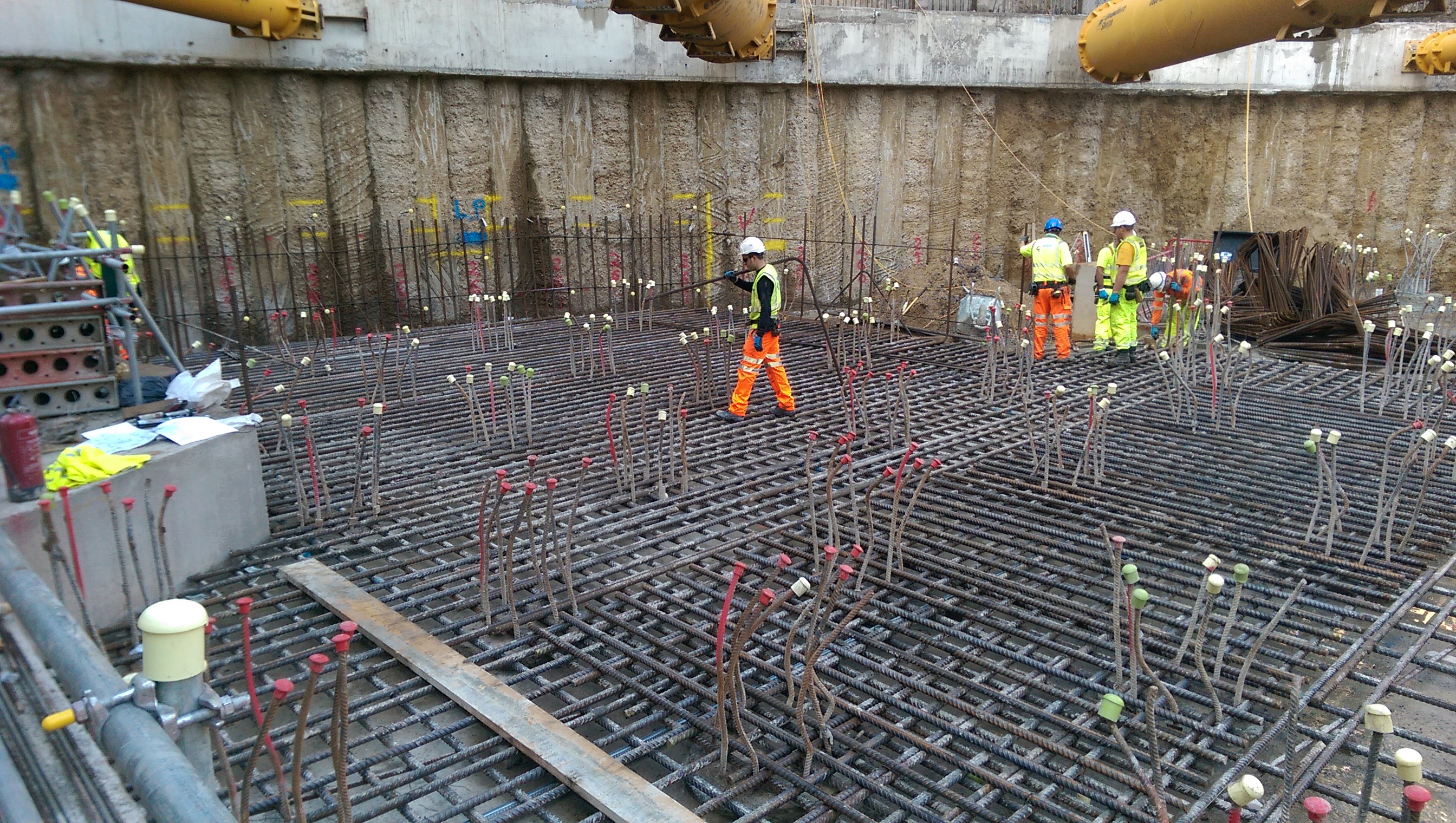
Raft bottom mat reinforcement being installed.
The original aim was to use Pecafil formwork (permanent sheeting) for the concrete pour. Due to the number of piles this is proving a little more complex. As the ground is excavated, pile reinforcement acts a bit like dragons teeth preventing easy access to return to backfill around the raft. The plan is continuing with the idea to use a small dumper to move material back into position, rather than switching to the use of shuttering. Again, more to follow on the success of this plan!
A final thought:
There is a slab (450mm) which will be poured across the site, including on top of the raft making a total of a 2.1m deep foundation.
There is a bottom mat to fix in the raft and a top mat to fix in the slab.
Would you, a) fix the bottom mat, pour the concrete raft then fix the top mat and pour the slab? Or, b) fix bottom and top mat, then pour raft, then pour slab (i.e. do pours with all steel fixed)?
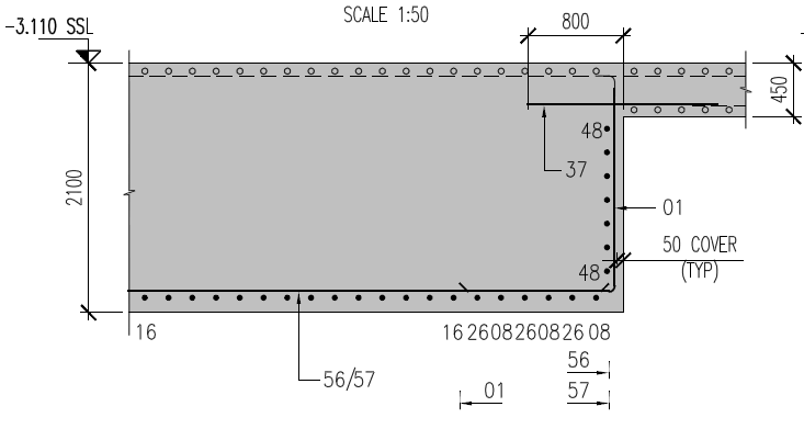
Raft foundation comprised of 450mm slab and 1650mm raft.
The Seven P’s.
In should come as no shock to anybody that water in is pretty expensive in South Australia, costing in the region of $3.32 per kl. The project received its first bill this month (don’t ask me why it has taken this long to get here) that covered the start of the project Dec – Apr which was quickly followed by a second covering May – Jul, with the total over $350,000. The cost arose from the fact that water was required almost 24hrs during the summer months for dust suppression during the bulk earth works. Surprisingly this cost was not captured in the budget for the project and was excluded from contract with the subcontractor responsible for the earth works, so it will eat in to the profit for the job.
From this episode the project team were tasked with carrying out a review of the budget to identify any other holes and quite a few were identified. The main one sticks with the water theme as it became apparent that the cost of filling the various systems on the site (in the region of 30Ml) with demineralised water had not been accounted for. The options for supplying this were limited, using the reverse osmosis plant at the local power station or getting in portable reverse osmosis plant to site to produce our own. The power station was discounted because in order to fill the tanks on site we would need to fill the 5km worth of pipe to get it here and find a method of pumping it. The current plan is to use a subcontractor to bring in temporary plant to produce it on site. This is producing a number of issues in itself, the main one is trying to find a subcontractor with the capability to do this, we are currently looking at GE supplying the equipment and another subcontractor to install and operate. Further issues we will need to work out on site include finding space for the plant, power and water to operate the plant and a method of discharging the brine, all of which the project will have in the future but not necessarily in time.
No one is sure what this is going to cost but best estimates coming from our procurement team at the moment are around $500,000, plus the cost of the feedwater approximately $100,000. This is likely to fall to John Holland, as the head contractor we are ultimately responsible for commissioning the plant (although no doubt we will try and push some of the cost back to the client).
Looking for causes as to how this could have been missed I think it’s quite simple, in the rush to get shovels into the ground after signing the contract a draft program was produced, with no product or work breakdown conducted to back it up. As the project progressed no one has had the time revisit the program so it has just been updated where necessary, which is fine for sequencing works, but doesn’t identify items that are missing altogether. In their defence I know at the time the project team was pretty limited and they were under immense pressure to get the project started.
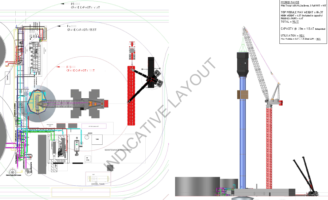
The picture below is just to attract some attention to this blog, it shows the planned lifting strategy for the 115m high tower, hopefully before I leave site in November.
Defence Reporter
I am not sure of how others come by their Thesis ideas, however I certainly didn’t find one drop in my lap from working on site and so had to go looking. I would encourage those in Phase 1 to start thinking about it before leaving Chatham. A resource I have found for contemporary research from DSTL is Defence Reporter:
https://www.gov.uk/government/publications/defence-reporter-mod-research-reports-on-athena
The periodical only gives the abstract and you have to apply for the reports which appear to get posted. Mark said he has used it before but the system appears to have been formalised more since. Some of the reports may be worth applying for, most certainly aren’t. The above link gives the back copies and you can subscribe, the issues are irregular but at worst it is four extra emails a year to delete from your junk mail!
Gut Feeling
Pre-amble
First I must apologise for not blogging for so long, as I’m sure you’re all on the edge of your seats waiting for my next instalment; I should have listened to those who warned me about parenthood!
This blog is regarding the design of a previously discussed project and conveniently reinforces what both Damo and Guz have just blogged about.
The Project – ETAP Lifeboat Maintenance Padeyes
Each of the 3 lifeboats on ETAP are lowered using a pair of winch cables attached forward and aft. The cable release mechanisms are sufficiently delicate that carrying out maintenance on the lifeboats requires maintenance strops to be used in order to provide a secure fixing to the structure in case of a release mechanism failure (size 10 boot). Due to new lifeboats being installed a couple of years ago, the maintenance padeyes are now considered under sized and out of alignment to the boat fixing locations. See figs 1 & 2.
Fig 1 – Existing South padeye

Fig 2 – Existing North padeye
The original solution
The solution was simple. Cut off the existing padeyes and weld new, uprated padeyes in new locations. See fig 3 & 4.

Fig 3 – Proposed South padeye

Fig 4 – Proposed North padeye
So what’s the problem?
This project has been ‘hanging around’ for some time and hasn’t really moved forward, not helped by the ever changing personalities (see future blog). Following a couple of meetings back in June, the BP Offshore Execution Lead expressed concern that ‘it just doesn’t feel right’ and although I agreed with him, I just put it down to being new, as well as accepting that circa £100k had already been spent getting this project through the design phase so far, surely it must be right?
The following were highlighted as being a concern;
- It was understood from handover that the lifeboats would remain in service. The plan requires a significant amount of scaffolding around each lifeboat which by virtue of the restrictions, takes the lifeboat out of service.
- The plan had all 3 lifeboats being worked on at the same time. This just wouldn’t happen due to the obvious sensitive nature of the lifeboats.
- The plan required an amount of hot works (grinding/cutting & welding). Although the lifeboats were not in an area which required additional measures to be taken (use of a habitat, for example), there was still a risk to the lifeboats themselves and layers of protection would be required; reinforcing point 1 above.
- The padeyes would require testing once welded in position. The plan used a jig that wrapped around the davit structure see fig 5, so that the forces would be self-contained and not add to the davit arms themselves. This required both heavy and awkward lifting above a lifeboat and inches from the edge of the platform.

Fig 5 – Test rig
The solution
Following a ‘deep dive’ an alternative idea was suggested which was solely a bolted design, see figs 6 & 7.

Fig 6 – New North padeye design
Fig 7 – New South padeye design
This design had the following benefits
1. No hot works are required which means less protection and less scaffolding reqd, which leads to a quicker install and a shorter time to get the lifeboat back into service.
2. Potential to construct using rope access only from the platform above. This would mean no scaffolding reqd and potentially reduce costs.
3. The entire frame could be proof tested onshore using a mock up davit arm/frame, and then re-assembled offshore.
So why wasn’t this option considered in the first place during the Appraise/Select phases?
It was, but as I understand it, was not selected because it did not look aesthetically pleasing!
Now what?
I am expecting a Project Change Notification (PCN) of between £50-100k to get this re-designed and ready for offshore construction, and potentially a delay to the ‘ready for construction’ date.
Conclusion
Even though a significant amount of time and resources had been spent on designing the solution, it does not mean it’s necessarily the right one. If it doesn’t feel right, it’s worth doing a ‘down, test and adjust’ to make sure the direction of travel is the right one, especially if the project has sat idle for some time and/or the entire team had changed.
This project is, technically, as simple as it gets. But from this blog and my previous, you will see that it is not straight forward and often it is the ‘so whats’ surrounding the project which add most of the complexities and frustrations.
In other news
Currently planning for phase 2 of the Grand Design, which incorporates replacing the boiler (expect a separate blog on this), getting drawings done for proposed extension and getting the final 2 rooms ready for move in. Pics to follow.

How big is the bus?
I am not sure whether the client usually gets to see the value of each of the subcontracts but it appears that we do. So for my FtIG project I can see that ‘the bus’ is costing us approximately $110,000 or 27.5% of the contract value. From what I have seen so far this pays for two slippery salesmen and an OAP in a portacabin who is going to run the site. Although we are supposed to get the information it has been accidentally added into the emergency contact submittal, which was clearly part of a larger spreadsheet, but you can get the idea

Contract values
Flippant as I may be this clearly also considers the various overheads that have been incurred not least the cost of tendering for the project and the 4 months of paperwork that has been done prior to getting out onto site. This in cash-flow terms is a significant burden for a small company. Also in there will be the risk for things not going well, something that is quite likely in replacing an old system. I am not sure whether Greg or Steve have any thoughts on the general mark up on something like this.
As far as progress goes, yesterday I met the aforementioned OAP who is to be the superintendent, Quality Control Manager and Site Safety and Health Officer (SSHO) and some materials were delivered. I took the opportunity to get some shots of the interior:
Left: Air conditioning unit not being replaced. Right: Two boilers being replaced.
Left: Three pumps, to be replaced with two pumps.
Right: Domestic Hot Water Heaters to be replaced.
Total Deadlock!!!
Just before my summer leave I attended the most frustrating meeting I think I will ever endure…it made a TFH ISTAR planning co-ord appear proactive!
The background
The embankment that approaches each bridge abutment has a series of piles called CMCs (Continuous Modulus Columns). These piles are placed on a 1m grid over the width of the road for around 50m. They do a number of things but mainly they stiffen the embankment material as they are displacment concrete piles and secondly they transfer some of the load through the constructed embankment to the stiff clay below. They contain no ReBar and are designed to fail if heavily overloaded.
The Problem
Given that the CMCs are not reinforced, they are designed to work in a specific way. Any structural movement will eat in to the tolerance of the CMCs, this means that it would be crazy to install the CMCs whilst our site is still undergoing large amount of settlement we’re still experiencing. Whilst the settlement is starting to slow it has not reduced to the level the Vibro Minard, the subby that is installing them has specified.
The Sticking Point
- Vibro will not give a warranty on the potential for differential settlement of the installation until the ground is at the strength originally specified.
- WSP, the designer, will not check the original spec or conduct any alteration without a FULL check of the whole scheme (big £££). Clearly they can see we’re over a barrel and know something has to give. Their argument is that a reduction in platform strength may have a fundamental impact elsewhere and that requires checking.
- We only have a six week window to get this done before it takes over as the critical path and causes programme delays.
- Kent Council are unlikely to accept the embankment without warranty (we don’t want to ask the question as it will likely open up a huge amount of questions and interest).
- We don’t have the budget to cover the warranty as the project is heavily in debt and this sort of warranty would be for an unknown sum given that no one internally really understands the actual design enough to predict what may happen.
We left the meeting looking at each other saying ‘so what now’.
So What
Quite simply we’re having to wait for the ground to ‘Get A Grip’ and toughen up.
We’ve conducted a number of onsite tests to check the current strength in the ground. The good news is that it’s higher than we expected based on the original model and pizo data however it’s not quite as high as we need.
We have asked the designer look over the findings a predict what the ground strength will be by the time Vibro mobilise if we give them the thumbs up now. It’s looking good, so fingers crossed.
The Disappointment
The sad thing was, everyone sat around that table knew how to solve the problem but hid behind lines like ‘this is what my design manager has said…’! Whilst I understand the requirement to make money, I will never understand the mentality that it is ok to do so whilst others fail, sink and lose out. What made it worse was the lack of spine demonstrated, if you’re going to represent your company then embrace the policies they set, don’t hide behind people who are not present in an attempt to deflect the criticism away from yourself.
The Good News
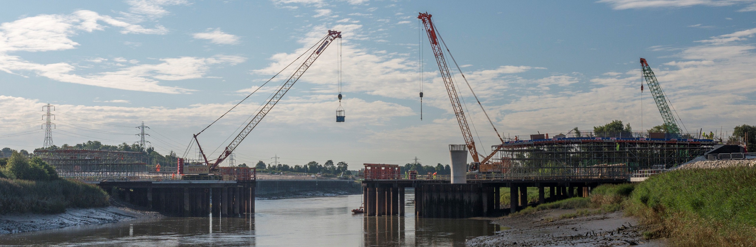
We have a structure that is starting to look like a bridge, peirs and all!
