The Rising Factory
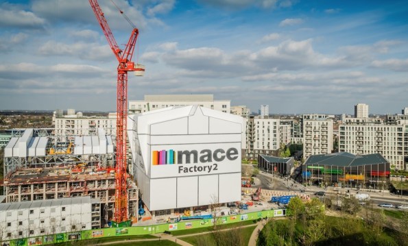
Figure 1. East Village, Stratford.
Summary
As part of the handover between Skanska and Mace, all Battersea phase 2 staff are getting various presentations from Mace to tempt us to join them. Yesterday we had a presentation which featured a different Mace project, East Village in London, which is being constructed in a really innovative way, and I thought I would share. I must stress that I have not worked on, visited (I am trying to arrange this) or even seen this site, and that my knowledge is restricted to what is contained in here. They are using jump forming of sorts, but instead of just producing a concrete core, they are raising the ‘rising factory’ to reveal a completed floor of the building. Interestingly, all lifting is done via gantry cranes inside the rising factory, utilising the riser shafts within the building. This negates the need for tower cranes (NB the tower crane in Figure 1 is for the surrounding construction) and eliminates down time due to high wind. The weatherproof factory environment also allows for safer construction year round.
Background
The jump form and slip form systems are well established, but what emerges is the raw core of a building with all the remaining elements still to be constructed, with all the associated programme disadvantages. The ‘rising factory’ is a 10 storey high enclosure inside which the construction of a complete multi-storey building takes place over 5 construction levels. What emerges as the factory is jacked up on its weekly cycle is a level of newly constructed building which from the outside is complete and just requires finishes to be applied internally. Cranes (including vehicle container offloading), storage and welfare facilities needed for the construction activities are all within the enclosure and varying types of activities happen at each level from construction of the structural columns and slabs at the top to completion and sealing of the cladding at the lowest level. A jacking system is permanently attached to the factory columns and the jacks engage with the support brackets when the factory makes its weekly lift. The factory facilitates the construction of a 30-storey building with a cycle of a week per floor, giving large programme and site health and safety benefits. These benefits are significant for all parties.
Operation
In 2016 Dorman Long Technology (DLT) were awarded the contract by Mace to supply two pinned climbing jack systems for the construction of twin residential towers at their East Village Development. The project aims to construct two high-rise residential towers using pre-cast concrete construction. The ‘rising factory’ concept is used to create a waterproof factory environment for construction and fit out of each floor. The scheme uses a temporary steel rising factory building erected over the top of each residential tower during construction, which contains two 15t gantry cranes. After each floor has been constructed the temporary steel rising factory is lifted by 3.3m by the 4 x DL-CP250 pinned climbing jacks which remain static, but lifts the climbing bar connected to the rising factory, allowing the next floor to be built.
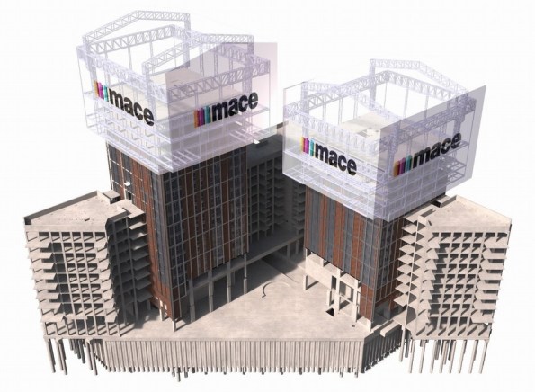
Figure 2. Image from 4D modelling.
The first jump of the rising factory was completed successfully in Feb 2017. During this jump the factory was raised 6.6m – twice the intended standard jump distance of 3.3m. This was to allow completion of assembly & cladding of the factory structure and construction of the next two floors of the 30 storey tower. Figure 3 and Figure 4 show the factory before and after the jump. The factory, which in this partial completed state weighed 565t, was lifted using four 250t DL-CP250 pinned climbing jacks controlled by DL-P40 computer control system, as shown in Figure 5.

Figure 3. Tower before jump.

Figure 4. Tower after jump.
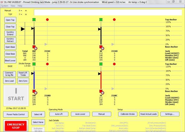
Figure 5. DL-P40 computer control system during jump
During construction of towers, the weight of the rising factory is supported by four hydraulically operated pins (Figure 7) which connect it to the high-rise building via four jump brackets, one fitted to each corner column of the building. All vertical and horizontal loads from the rising factory are transferred to the building via these pins. During factory operation the pinned climbing jacks (Figure 6) and climbing bars are not subjected to any imposed loads. During the jacking of the factory the pins are hydraulically withdrawn and the pinned climbing jacks lift the climbing bars which are fitted to the rising factory. The pinned climbing jacks are each mounted on top of a jump bracket via a pair of link plates.

Figure 6. DL-CP250 Pinned Climbing Jack.

Figure 7. Hydraulically operated pin.
Conclusions
This method appears to offer huge benefits to construction, but like many innovative techniques, it must be chosen early in the design stage. The footprint of the building must not be too big, and the risers must be sufficiently large and appropriately placed to allow all of the required materials to be lifted through them. Although this case study uses pre-cast concrete elements (saving further time) I cannot see why it could not be adapted to contain a concrete pump and use cast-in-situ construction if desired. The benefits are obvious, and although there are numerous projects where this construction method will not be suitable, I expect to see an increase in the use of rising factories.
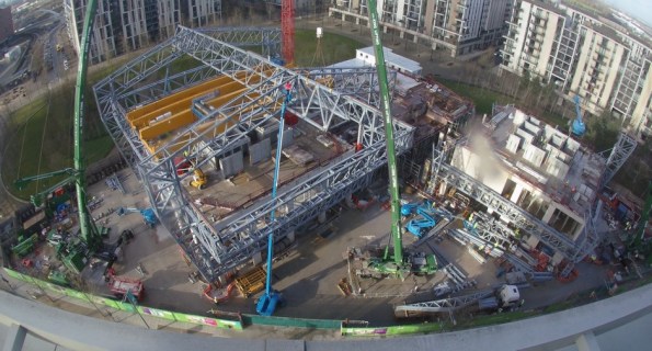
Figure 8. The rising factory from above.
A Forgotten Post: Almost a Civil Engineer…?
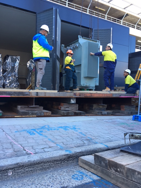
Task Overview. Part of the Substation Scope of Works was the installation of two 1500 kVA transformers, both weighing 5000 kg.
Expedient Engineering Opportunity. Initially functioning as a supervisor to the wider-Substation construction, it was during a routine meeting that I noticed no detailed plan existed to safely install the transformers. The original idea to lower transformers into the Substation had overlooked that the roof and doors to the structure were installed early. (At the time, the Project Manager thought this was a “quick win”.)
I resolved this issue by devising a plan to design and construct a temporary platform in order to safely install the transformers. Realising my very limited Civil Engineering competency, I engaged with an approved subcontractor – Shore Hire – to develop my concept into a legally recognisable design, should something go wrong; I achieved assurance by requesting a design certification from Shore Hire’s engineers.
Pictures: (Top to Bottom) Initial proposal; detailed design from Subcontractor; design constructed; and, transformer being released from the crane and wheeled into position.


Until next time…
BP – pipe support loads
Alongside project delivery I am currently working as part of the mechanical discipline engineering team. The work I am doing for them is answering Design Technical Queries (DTQ) and Engineering Queries. I started trying to explain both but it became too wordy, the DTQ is explained below:
A DTQ was submitted in relation to the pipe support loads experienced during a blast event along new production flowlines that are due to be installed (some have actually already been installed). The Clair platform has legacy issues relating to blast whereby the original platform design was never designed for blast. As such, all current in-use flowlines and pre-invested (installed but not hooked up) are supported using standard U-bolt pipe supports. The U-bolts are not designed to be able to withstand a blast event since the primary load path for the bolts is vertical. The U-bolt manufacturer only specifies a max vertical load therefore a max lateral load must be assumed.
Wood Group are the contractor designing the new flowlines (to be tied into pre-invested) and are concerned that in the event of a blast a number of the pipe supports will fail due to excessive lateral loads. Their basis for this statement is a rule of thumb that the max lateral load is a nominal 30% of the max vertical load. The manufacturer stated max vertical load is based upon the yield stress of the material. They have asked if they are to replace all the pipe supports since they all fail.
Recognising there are platform wide issues relating to blast, Fraser-Nash Consultants (F-N) were contracted to conduct targeted blast analysis on a complete flowline (one designed IAW original platform design). By modelling the U-bolt failure load using a similar method as Wood Group, F-N came to the same conclusion that the lateral loads are excessive. In order to understand the actual post-yield material characteristics (ie strain hardening etc.), a nonlinear analysis was conducted based upon the U-bolt geometry and material. From this they were able to establish a plastic collapse load. When modelled in this manner all the U-bolts were found to remain within the plastic collapse load. The picture I’ve attached kind of explains this problem through the stress-strain graph.


My response to the DTQ was initially to accept the F-N analysis since the U-bolts do not collapse fully, maintaining some structural integrity. My justification for this was that the design event is blast, a one-off whereby the performance criteria is to maintain primary containment. No-one seems content with this response and I am now stuck trying to provide more justification, any ideas?
One Nine Elms
Hi All, It’s a long one with few pictures, but interesting……. I think.
A recent series of events on One Nine Elms has left me wondering why project managers get paid ‘the big bucks’.
A new project manager has recently started in the project team, he previously worked on the project for McGees before joining Multiplex about 2 years ago. As such he has a good understanding of the project with exception of the sewer complications. Anyway he has arrived to impress the two project directors, with his current mantra being progress at all costs, which has potentially had some significant cost implications for Multiplex.
The diaphragm wall has been constructed under a design and build contract by Balfour Beatty Ground Engineer (BBGE), who Is contracted directly to the client. The first main contractor, CI- ONE, had a traditional bottom up sequence with props below or above the permanent basement slabs. This is what the wall was originally designed and partly constructed for. Balfour Beatty then became the main contractor (on a PCSA), and they changed the methodology to top down. This different sequence was re-checked against the as built wall, with BBGE confirming the design was sufficient. When Balfour Beatty and the client were unable to agree on cost and programme, Multiplex won the subsequent re-tender on a semi-top methodology which I have mentioned in a previous blog. Crucially as MPX did not signed the head contract until July and potentially not doing an in depth review of the project risks, they recommended to the client that the new sequence be checked again, instead of spending the c£40k themselves. As a result this check only started about 6 weeks ago despite Multiplex starting on site in January.
In the meantime, Multiplex have tendered, appointed and started on site the basement box subcontractor. As a result there is significant pressure to justify the subcontractors preliminaries and see some progress, i.e. Excavation to B1 formation. Armed with the fact that AKT (structural designers) had conducted a study confirming the D Wall could cantilever from B1, the new project manager actively encouraged the basement package manager to commence excavation. At this point both the project engineer and I advised that this was unwise, BBGE had not yet ‘approved’ the new sequence and there was no deflection monitoring in place. The Project and Package Manager came back with AKT have approved the sequence and an interim monitoring package has been signed with ITM. When I said that BBGE will not give warranty on their work (c£35M) if excavation commences without the approval of the sequence, I was told not to worry about the contractual stuff.
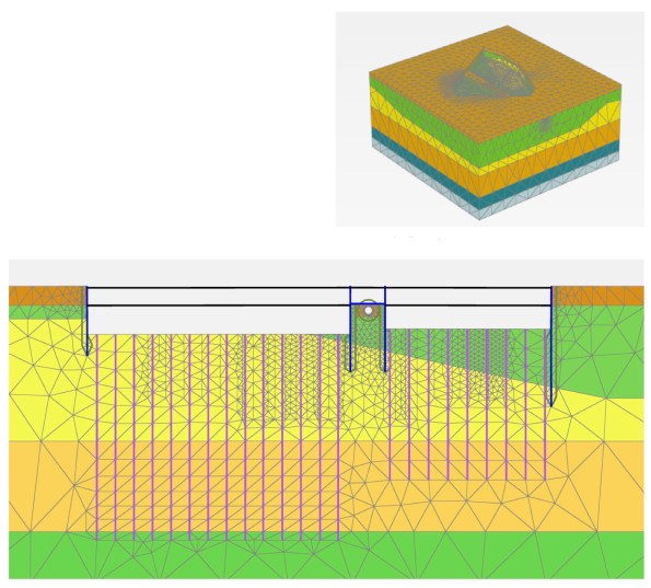
The week before the excavation started, BBGE returned the calculations for section of Wall where excavation was planned to start. The calculations showed the wall was acceptable under ULS but not SLS. The retained soil has high sulphate content, therefore the concrete exposure class is XC3, which has a. crack width limit of 0.3mm. The new sequence SLS moments cause cracks which exceeded this (theoretically), therefore the new sequence is not acceptable to BBGE. This was known before excavation and a number of things are currently being looked at to get this cracking issue to be acceptable. Interestingly during the first sequence change, BBGE could not get the deflections within limits in their WALLAP calculations. As a result AKT modelled the basement in 3D FE and have taken responsibility for deflections, slightly worryingly BBGE deflections are an order of magnitude higher.
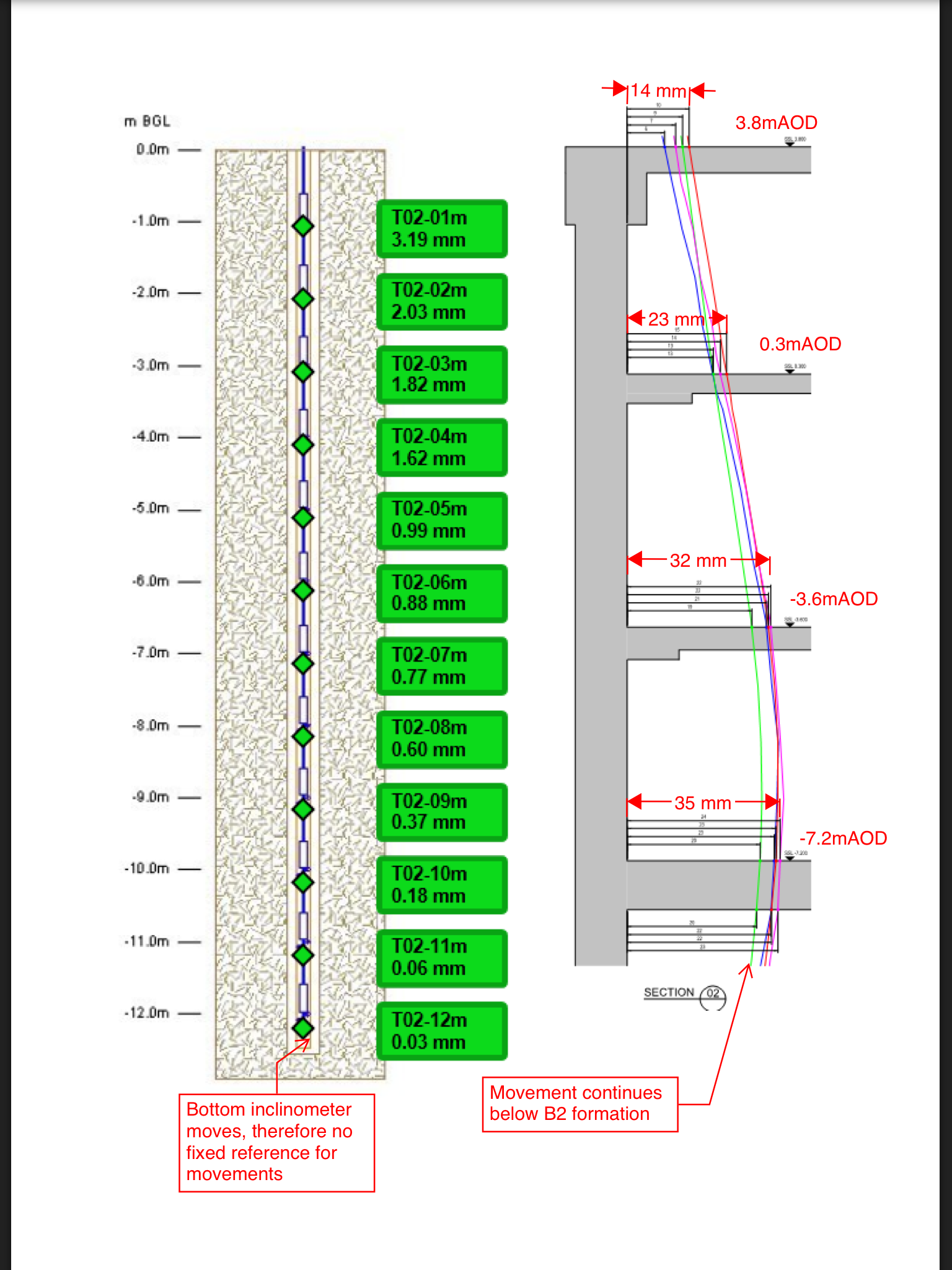
Despite this excavation commenced, with active encouragement from the project manager and construction director. With this in mind, the last thing you would want is a poor monitoring package. By chance I was asked to chair ITMs (monitoring company) pre-start meeting on behalf of the package manager, who had effectively tendered the package. It quickly became apparent that the inclinometers are not fit for purpose. They only went to B2 formation level where there would still be significant movement. This means the head of the inclinometer would need surveying manually in order to provide a reference point to baseline the inclinometer, not good for an automatic system to rely on the manual input of data to work. Furthermore it would appear that this manual reading had only been bought to be conducted once a week.
So, Multiplex have basically started excavation without approval from the designer and without any deflection monitoring in place. Low and behold, the client receives a letter from BBGE, informing them that they cannot offer warranties on their works because Multiplex have excavated not to the approved sequence and with no monitoring. The project manager and construction direction then hit the roof and basically blame the package manager, conveniently forgetting their encouragement to start excavation.
The result of this is not yet known. The two individuals had been given sound advice which they chose to ignore, they then tried to blame everyone but themselves. Poor management, decision making and leadership from individuals paid a lot to do this well.
Fellow Multiplexers don’t show this to anyone in the company.
Health & Safety: The Journal Continues…
Here you have it sports fans, more snaps from my Health & Safety Journal!
That’ll do there!

Stored High in Transit (SHIT)

Do I really need to conduct a Confined Working Space Assessment?

Much Ado About Nothing?
Situation
When passing by the site offices I noticed the pulley system scaffolders had erected to speed their delivery of materials up a 12m viaduct wall, instead of using the stairs. I didn’t take a second look at first, as it looked like a routine and simple operation that they would carry out on a regular basis and “they must well know what they’re doing” it’s their specialist trade as scaffolders. However, I hadn’t previously checked their RAMS as this had been done by someone else so I was coming at this with a fresh pair of eyes.

Options
- Do nothing – it looks fine and is likely capable of lifting scaffold equipment. They must know what they’re doing.
- Question the scaffolders to get a confirmation that they are using the correct methods and that they know what they’re doing – I know they’ll tell me what I want to hear.
- Stop their works and do some checks. It just doesn’t look right.
I opted for the third one.
Issues
I used a method I recently learnt at a Multiplex 2 day quality training session I attended which included the use of fishbone diagrams for finding the root cause of nonconformities. Dubious as I was to their use, it provided another variation to a mind map. This gave me a number of routes to explore but I’m sure I will have missed elements out.

What appeared to be a simple situation can have a lot more to it as I found out:
- Work not covered in the RAMS. I checked their RAMS which had been filled out for the works to be undertaken on top of the viaduct but had not included delivery method and movements of stores. The RAMS had been checked but were not including the use of the pulley and therefore was not picked up. If it had included the lifting operation then the lifting operations coordinator would have been included in the checking of the RAMS. This means that the works shouldn’t have been carried out because they were not in accordance with the RAMS. The conformity and signing up to the use of RAMS is done by each individual at induction on site. This confirmed it was right to stop the works until the RAMS was amended and resubmitted for approval.
- Scaffold incorrectly constructed/not appropriate. What appeared to be a simple pulley mechanism was lacking moment carrying capacity. Looking at the setup I remembered portal frames and that if the load were to be transferred through 90 degrees, there would likely be a big bit of steel required at the haunch to deal with the induced moment. But surely they know what they’re doing and the scaffold connection is designed to carry the load? No – a diagonal member is required to carry the vertical load. This was not in place.
- Mechanism incorrectly fitted. After googling the pulley brand, it turned out they were using it the wrong way round and the brake wasn’t working – this made me think there was a lack of training somewhere in this mix of issues and that there could be other issues regarding the training.
- Knots. Individuals using knots to secure loads to rope must be level 1 trained. The previous item made me wonder whether this was the case and so I requested proof of their training – handily held on a CSCS card, copies of which are retained during the induction process on site. It turned out the individual was correctly qualified.
- Not valid document for pulley. The pulley itself was not provided with a test certificate. When asked to provide one there was a delay before a certificate was supplied. It came from the scaffolders’ office and is likely to have been put together following that request. However, there was no way of disproving this.

Learning Points
I consulted the HSE website, LOLER and the pulley’s operating and maintenance instructions (links supplied below), and have put together the following key points for the correct set up and use of a scaffold pulley wheel:
- The scaffold gallow bracket must be correctly erected (90 degrees with diagonal brace).
- The horizontal tube from which the pulley wheel is suspended should be fixed with right angled couplers to both the inner and outer standards.
- The Pulley wheel must have a fully functional brake (the braking action is compulsory and shall be automatic when the operating force ceases, whether the motion is lifting or lowering).
- Ropes must be the correct size to suit each type of pulley wheel (usually 18mm).
- If the rope has a hook attached for the purpose of lifting loads then it must be a safety hook, correctly spliced to the rope at point of manufacture.
- The pulley must be tested and examined before use and every 6 months thereafter (certification to this effect must be issued.)
- Weekly LOLER inspection of the wheel and rope must be undertaken by a competent person and the results recorded.
- Materials must only be attached to the rope by an appointed loader handler who is authorized, with evidence provided that they have received the necessary information, instruction and practical experience, particularly in the types of knots used to secure loads (minimum requirement must be COT course, H&S test and CISRS Trainee Part 1 Pass).
Conclusion
The most frequent causes of incidents regarding pulleys relate to the inadequate attachment of the load to the rope, the incorrect attachment of the wheel itself and a non-functioning brake. Specialist trades are assumed to know their methods of work and it is easy to think they have the definitive knowledge of a subject. However, whilst implementing their skills at the lowest level they may be using equipment they haven’t touched for some time or are unfamiliar with.
References:
CAP 609 General Information Booklet
Requirements for all “thorough examination” documents
Scaffold CIRSR training booklet and website “Construction Industry Scaffold Record Scheme”
Moment Capacity For Circular Pile Section! Any Thoughts?
During a routine inspection of pile caps prior to concrete this morning, I identified that one of the piles was offset by 216mm! At first glance it didn’t look that significant. However, the drawings highlighted a tolerance in plan of 75mm and the Mecc in the pile design was 206Knm! A Non-Conformance Report (NCR) was issued to the groundworks subcontractor immediately and they were told to assess the impact.
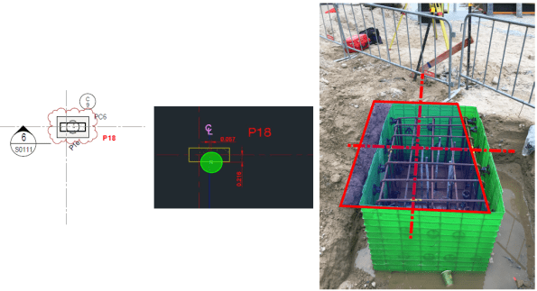
Markup used to highlight problem for NCR. Dashed line shows actual C/L for column.
This would have an impact on the pile and the pile caps, which were procured via 2 different subcontract packages with 2 different design consultants. Because of this I knew that a resolution wasn’t coming anytime soon and I wanted to complete some of my own checks.
I could see 2 potential problems with this:
- You can see in the image above that the steel fixers have just plonked the reo cage for the cap directly over the pile, which leaves the column off centre on the pile cap. This would create some bending stress in the pile cap and tension stresses may develop in the concrete = BAD. (Did quick P/A – M/Z = -0.5 N/mm2! Not sure how significant that is?)
- If the pile cap is moved back into the correct position (outlined in red above); then the pile is offset = Moment created in pile head due to eccentricity.
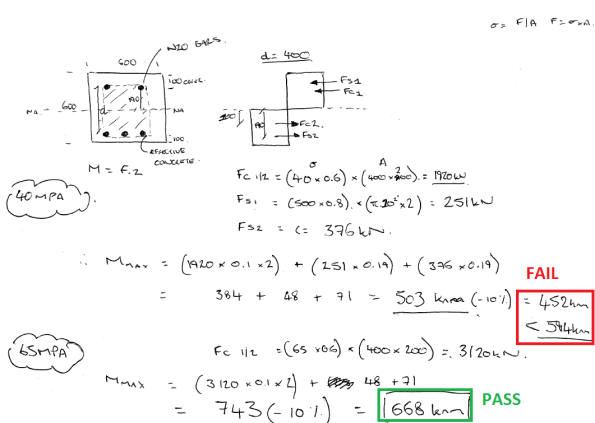
The images below show a section through the problem and some rough calculations. In summary, the moment created by the eccentricity is 594Knm and a quick strut and tie model identified a tensile force of 634KN in the top of the cap, therefore, Ast required = 1585 mm2. The current N16 @250 E.W.T.B was insufficient and I think additional steel ties will be required in the top of the pile cap. Not a showstopper.


I THEN HIT A WALL!! HOW DO YOU CALCULATE THE MOMENT CAPACITY OF A CIRCULAR SECTION?
I’m sure the answer is glaringly obvious, but I couldn’t get my head around it. As an alternative I transformed the circular section into a square section and reduced its capacity by 10%.
Whilst checking the ITPs for the CFA piles, I also identified that the concrete strength used was 65 Mpa, despite the design and construction drawings only calling for 40 Mpa. Nobody on site can recall why 65Mpa mix was used, but my calculations show that this apparent mistake could actually have increased the piles flexural capacity enough to resolve this issue!
Below are my calculations for Mmax. If anyone can provide a solution for a circular section it would be much appreciated.
Blast Analysis in the Urban Environment Lecture
Blast Analysis in the Urban Environment
The Institution of Structural Engineers is running a series of lectures, this one I think is particularly interesting, it is the penultimate one in the series.
| Date | 27 September 2017 |
| Time | 17:30 for 18:00 start |
| Venue | The Institution of Structural Engineers, 47-58 Bastwick Street, London, EC1V 3PS, UK |
| Speaker | Nick Misselbrook – Associate Principal and Office Director, Thornton Tomasetti Defence Ltd. |
Description
Protective building design requires a detailed understanding of blast loads and explosion damage mechanics. Many of the tools available for blast analysis are based upon a combination of empirical data, analytical approximations and scaling rules, which are not always accurate for explosive events in complex urban environments.This lecture will give an overview of the blast analysis tools currently available, demonstrating where and when such tools are valid, and a look at state of the art possibilities.
Speaker
Nick Misselbrook is an Associate Principal and Office Director for Thornton Tomasetti Defence Ltd. Nick has an MSc in Weapons Effects on Structures from the Royal Military College of Science, is a Chartered Engineering and Chartered Physicist and a Member of the Register of Security Engineers and Specialists.
The lecture is free and you can register at the link below.
There is also a webinar and database of previous lectures from the series.
https://www.istructe.org/techlecseries
The final lecture is on the 5 October – ‘The success and potential failure of engineering computational design’. Details can be found at the above links.
Planes, Trains & Automobiles
The Airport East project has displayed the importance of management of stakeholder relations to ensure the smooth running of a site.
Roads and Maritime Services (RMS), Australian Rail Track Corporation (ARTC) & Sydney Airport Corporation Limited (SACL), are the three biggest stakeholders on the Airport East site and known affectionately as the three amigos. The contract is construct only and a number of clarifications are submitted to RMS daily, which in turn do lead sometimes compensation claims. SACL own the land but also impose tight restriction on operations due to the proximity of the E-W runway. ARTC operate the main freight line which runs to Port Botany which dissects the site and is also being upgraded as part of the project to dual lines, they also impose tight restriction and limit access to the rail corridor.
During installation of reinforcement for Span 1 of the Canal Bridge, RMS were still changing their minds right up to 3 hours before the pour of where they wanted to locate conduits for traffic lights and lighting for the bridge. Retrospectively fitting conduits into slab reinforcement is a time consuming process. This is a lesson I will be taking forward for when the ducts are fitted into the Rail Bridge for post tensioning. It is key reinforcement is staged with conduits or ducts being fitted prior to the B layer of reinforcement being placed.

Figure 1 – Conduits for traffic control systems run through the cast-in-situ bridge deck of Span 1 of the Canal Bridge
One of the most exciting yet exhausting tasks I have been package manager for on site has been the installation of sixty precast pretensioned bridge beams for Span 2 of the Canal Bridge. I have taken this process from competitive tender, standard subcontract and award, through to installation. The tasks leading up to their installation involved; authoring the activity method statement, excavation and removal of the temporary piling platform in the canal, checks to stressing calculations for the bridge beams, quality inspections of the prestressing yard, application to SACL for a week long closure of the E-W runway for 220T telescopic crane, design and validation of the crane platform, oversized load permit for delivery to site of the beams, organisation of haulage, medium risk lift plan for installation, and being lead engineer co-ordinating the landing of each beam onto temporary bearings. Choreographing their installation over 4 days, involved 15 being delivered per day, a truly rewarding task once they were all secured in place.
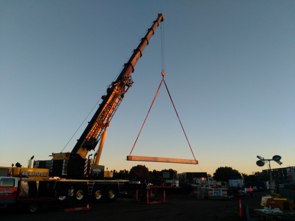
Figure 2 – The one of sixty precast bridge beams is lifted into position for Span 2 of the Canal Bridge
During installation I received a telephone call from SACL, the wind had picked up so for safety reason they needed to reopen the E-W runway. 15 minutes after the crane was lowered, the photo in Figure 3 was taken as an A380 passes over the site, showing the reason for the imposed height restrictions. This delay forced installation operations to cease until that evening when the Airport closed between 2300 – 0455hrs.
 Figure 3 – SACL reopen the E-W runway of Sydney Airport during installation of the beams forcing installation operations to be postponed to the night.
My relationship with ARTC will grow as I move onto Project Engineer for the Rail Bridge and Underpass this month.
Beams with a twist
I would appreciated peoples thoughts on the below issue I have encountered on site.
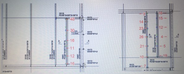
ISSUE: The steel frame erection is generally progressing well on site with approximately 90% of the steel work now erected. Unfortunately a recent site inspection highlighted that some of the secondary steel beams to level 02 had developed a twist in the member (see below). Level 03 above is a cantilevered deck which is currently temporarily supported through diagonal bracing.


The tolerances for the steel work on the project are laid down in the Structural Steel work Specification developed by Ramboll. These are in addition to the requirements of the National Structural Steel work Specification (NSSS). However, establishing the tolerances for the twist has proved more difficult than first thought. The steel contractor is currently attempting to determine a root sum squared answer from the fabrication and erection tolerances. In the meantime the visual distortion has been enough to instigate further investigation.
An as-built survey conducted by the steel work contractor confirmed the following ‘out of tolerances’ for three of the beams highlighted on site.
OPTIONS: The two options as I see it are to either leave it as it is, or to release the members and conduct remedial works as necessary. In both situations an evaluation of the significance of the twist is required to be made.
- Assess the structural significance of the twist. If not significant then do nothing and except the visual impact.
- Assess the structural significance of the twist. If not significant then do nothing, but weld a plate to the bottom flange in order to mitigate the visual impact.
- Assess the structural significance of the twist. If significant, release the connection. Relocate fin plate on primary beam to accommodate altered position of the secondary.
We are currently finding that, possibly due to the consequences, neither the structural engineers nor the steel subcontractor are willing to comment on the structural implications of the twist to the members and subsequently commit to a strategy moving forward. We are due to remove the temporary bracing in the near future. It is hoped that this along with the erection of the cladding will counteract the twist, however it is unlikely to counter it to the extent required.
It would be interesting to hear the thoughts of others with regard to the issue and potential remedial options? I would have thought that this issue must have been encountered previously through the experience of others? Any feedback is appreciated. Cheers, Al.
