Phase 2 Placements
To all C’s,
The time is now upon us students in phase 1 to start looking for our placements. There are at least 7 of us staying in the UK, with the majority looking to work in London.
Do you know of any interesting projects coming up within your companies that would be good for us to jump on in March 17, or will there still be work on your sites which we could take over, and if so can you give us an outline of what that work would involve?
Finally, do you have any tips for finding placements other than scanning through Construction Enquirer which it currently our main point of reference. Any information would be greatly appreciated.
Contract Admin…
Having recently moved into the Contract Admin office for a couple of weeks I have had my eyes opened to a few things.

It appears there are several major subcontractors who have been working on site for the last few weeks without a contract. This issue has raised its head as we are currently processing many of the subbies’ progress claims and the figures aren’t adding up. The differing figures result from conflicting terms and condition. Unfortunately, as much of the works are underway, Multiplex has little leverage as the cost of replacing the subbies almost definitely outweigh the benefits. This means the subbies are in a very powerful position and are almost dictating their terms. It has also caused cash flow issues for some of the leaner companies as their anticipated millionaires’ weekend has been postponed. We are now exercising diplomacy and smoothing over the frictions, whilst also attempting to negotiate reasonable terms and conditions in order to finalise the contracts.
The contracts in question were the responsibility of an administrator who recently left without closing them out. Signed off, switched off…
Whilst on the subject of contracts, below is a link which may be of use to anyone else about to enter the CA world…
Farmyard Acceptance Test
Aiming to broaden my attachment experiences, I volunteered to be the client’s representative for witnessing a Factory Acceptance Test of a Medium / Low Temp Hot Water plate heat exchanger set being installed as part of another project.
Perhaps naively, for a piece of equipment coming in approx. £80-100k I expected the factory to have a roof, floor, some walls and a clean(ish) environment. Instead, I met the fabricators on a dusty farm outside Basildon in Essex. I half expected Del boy and Rodney to come around the corner to take me through it.
It turned out that, despite first impressions, they had done a reasonable job spatially, improving what were very cluttered design drawings into a much better arrangement from a maintenance point of view. Valves and key items such as the distribution pumps and dirt / air separators were much easier to access and remove if required than in the original design. Having said that, all the equipment was stored in the open air (in a working farmyard), almost every pipe viewed was surface corroded inside, and the minimum design separation distance of feed and return pipework connections in the header had not been met.
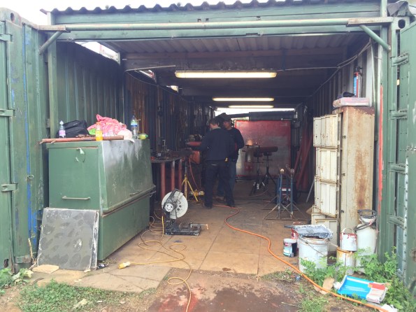
Welding workshop:
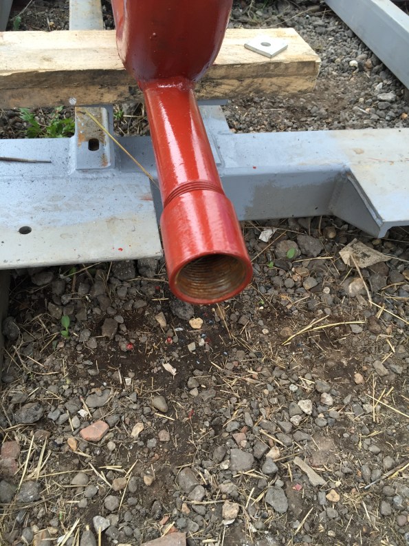
Internal corrosion:
I registered all issues into a report for review by the Contractor and the wider GAL project team and requested confirmation of remediation plan for the internal corrosion of the pipework and protection of the equipment from further weather damage.
I’d be very interested if anyone else has done a FAT on a similar system and what the construction environment was like? Also, any views on the significance of rust inside nearly all the pipes – I haven’t dug into the design calculations of the system but I imagine the pumps were designed to meet certain frictional losses which would have been increased from the corrosion to some extent? Could a decent cleaning flush when installed with subsequent inhibitor application during installation be sufficient to smooth / protect the internal surface?
Plate Heat Exchangers (painted blue):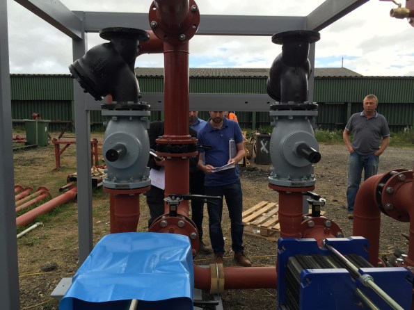
Separately and in an unfortunately similar vein to Kuki’s death on site blog, one of the baggage handlers lost his legs the other week. He was breaking strict protocol by stepping between baggage dolly’s (trailers), when the tug pulled away and he got dragged under one of the dolly’s. A sad reminder of potential catastrophic result of complacency in the work place.
Friday routine
Unfortunately due to the amount of services design development still required on the St George Hospital Project (we had our topping out party this weekend, so the fact we are still designing the services is worrying) I do not get to spend that much time actually on the site. Instead I find myself doing a large amount of work for sub-contractors to get their designs and documentation correct and sitting in user workshops where different sets of users change the decisions that were made the week before. However, every Friday I am set free from the office for the critical job of witnessing the Fire Damper testing – this is not quite as glamorous as you might expect. The picture below shows my typical view for most of the test:

That’s Gary, he’s from the Mechanical sub-contractors and actually does the test. Once the damper has been dropped I then get to check it correctly closed the duct, if I am really lucky he even lets me rest the damper.
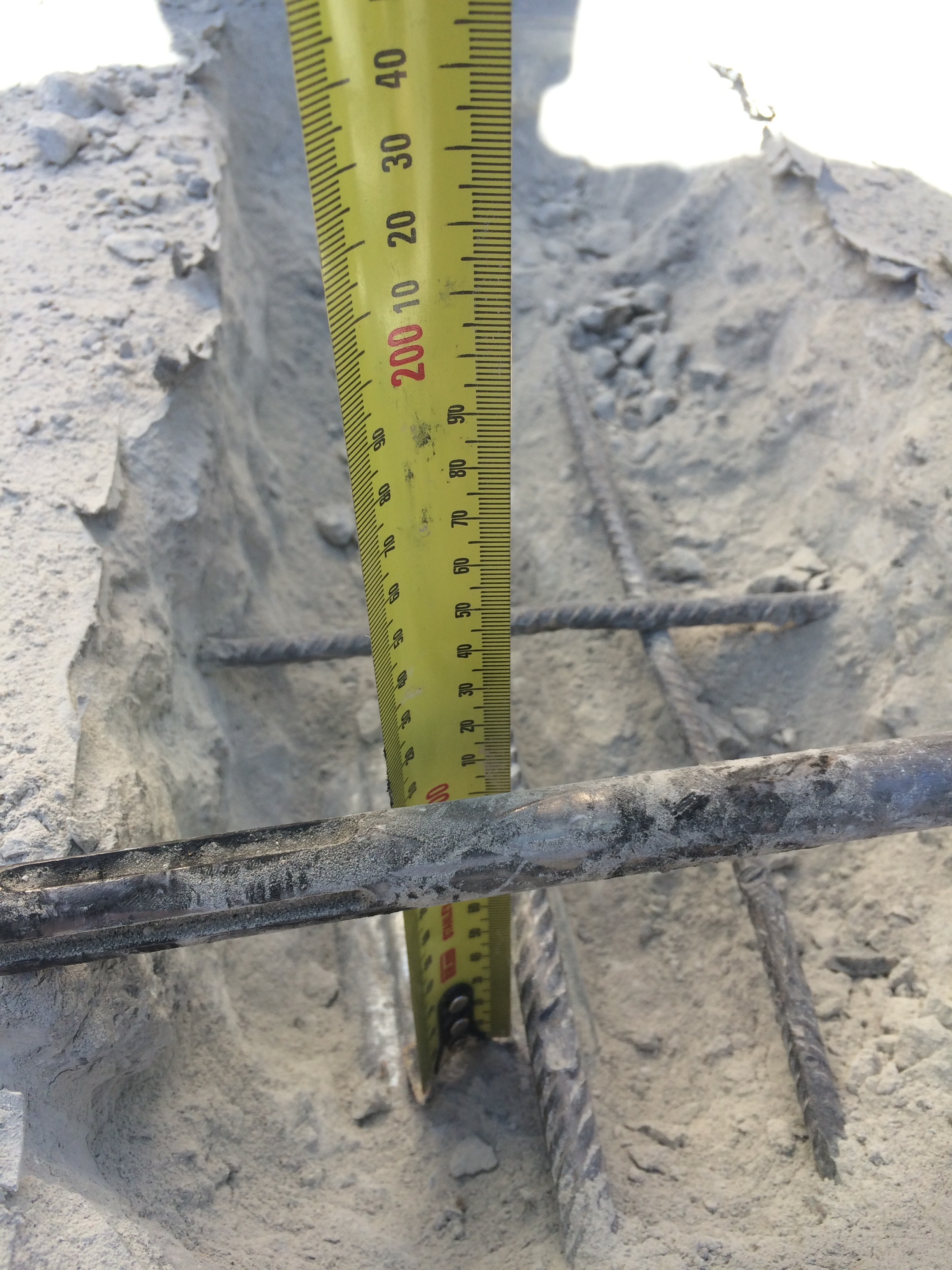
So rather than waste too much time staring at Gary’s bottom, I take the opportunity to look for defects in the installation of the various trades. Usually this is to do with penetrations through fire walls. The top 2 images below show cabling in fire walls that is not spaced at the mandated 200mm (the top left is difficult to see as the offending cables are pink).
The bottom left image shows a fire collar that has been used to attempt to hide a very large gap between hydraulic pipe and fire wall. The final image shows a fire damper penetration that is 7mm too big – and apparently 7mm is a big deal!


In line with Doug’s theme of things that went wrong this week…
When plasterboard meets water.


When there is no space for concrete in the slab because it is full of conduit.


Stay tuned for next week’s exciting episode that will feature Asbestos and a H&S person who expects me to have samples taken for every 25m^2 of a 125,000m^2 hospital: at $200 per sample, that is a nice round $1,000,000!
Oh well, at least it is the weekend…
Core wall modifications
Work has progressed significantly on site now. We have poured the basement slab, got the pre-cast walls to ground level installed, poured the internal core walls to basement level and completed the first pour of the ground floor slab. By the end of this month we should hopefully be well and truly out of the ground.


We have encountered quite a major issue on site during the last 24 hours with the external core walls. The wall was designed very close to its capacity with the strength being increased from 80MPa to 100MPa to make it work. The subcontractor responsible for the core capping beam has installed the starter bars for the walls 100-150mm out of position thereby reducing the effective depth of the wall by close to 10% as well as its capacity. This reduction in effective depth has tipped the wall over the edge and it no longer has the capacity to take the compression forces in the corner – the forces modelled are >150MN.
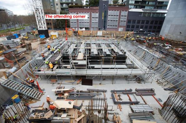
So what? The wall has been modelled and designed as a wall but due to the nature of the forces it must now be designed as a column which means compression ties. This will be fun when your wall currently looks like this….
Top Errors of the week No2
So we have finished digging and have started to build back up. I have moved to the Contract Admin department to focus on getting a bit of commercial experience and prep for the removal of the temporary supports.
In the last week we have finished of Basement 6 and have poured three quarters of Basement 5. The productivity has really got to some people and we have had a number of safety incidents this week. I have had to adjust this as I have just heard of another classic.
In 5th place is the site supervisor who poured 100 MPa concrete into a 50 MPa column, failed to puddle poured a 20 MPa slab, and then continued to pour a 100 MPa column on top. We now have a 20 MPa weak spot in an otherwise overly stiff column.
In 4th place is the guy who electricuted himself while drilling in a puddle. He is ok but, the site was shut down for 2 hrs.
3rd place goes to the guy who brought his own cutter on site which had some of the wires exposed resulting him getting a shock. He too is ok but, another loss of 2 hrs.
2nd place goes to the guy cutting rebar next to a spray can and the sparks caused the spray can to explode – no injuries but site shut down for two hours.
This week’s top pick though has to be the idiot who cut holes in my ground anchor walers to get his falsework in. The designers are after welding steel plate back on but, this will delay our programme. So this is now an issue. When I was inspecting the damage one of the formworkers then told me it was shocking that they hadn’t cut off more! Looks like it is time to bust some calcs.
![IMG_4577[1].jpg](https://pewpetblog.com/wp-content/uploads/2016/09/img_45771.jpg?w=595)
![IMG_4595[1].JPG](https://pewpetblog.com/wp-content/uploads/2016/09/img_45951.jpg?w=595)
![IMG_4591[1].JPG](https://pewpetblog.com/wp-content/uploads/2016/09/img_45911.jpg?w=595)
Modification of post tensioned concrete: update…
In my last blog I explained how I was planning the modification of an existing post tensioned slab, here is a quick reminder…
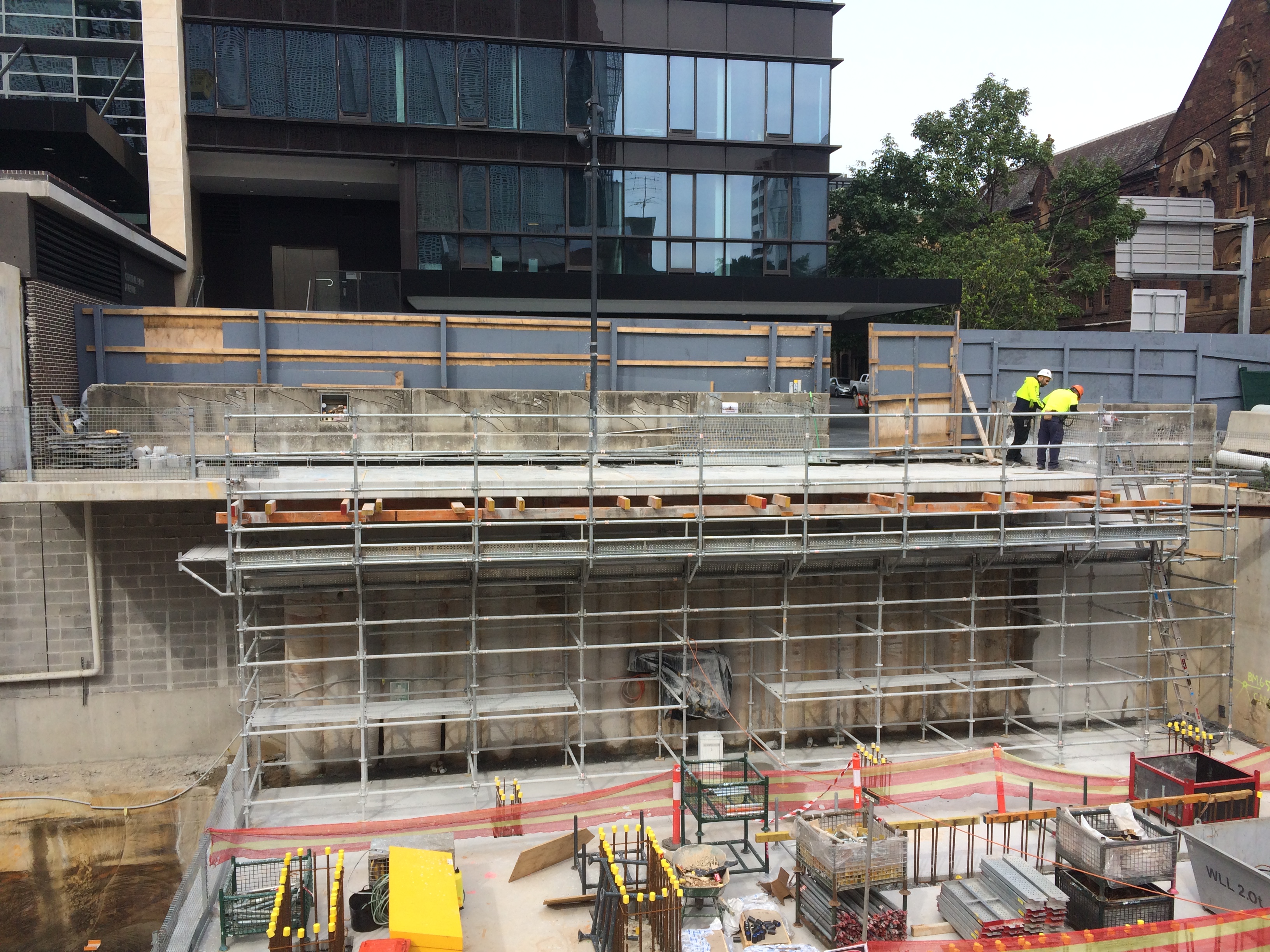
For unknown reasons the ground floor slab of an adjacent building cantilevered into our site by approx 2m. As we are building a bottom-up 4 level basement, this intrusion obstructed progress.
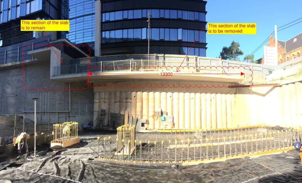
Step 1: In order to remove the offending section (2m x 14m, 250mm thk), we first analysed the likely effect on the remaining slab. This was anticipated to be between 2 and 5mm – acceptable. Step 2: We constructed falsework to the underside of the section being removed to allow the section to be temporarily supported between being cut and lifted out. This falsework also provided access for the crane crew and edge protection during the cutting process.
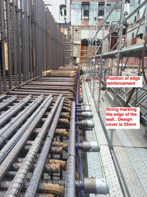
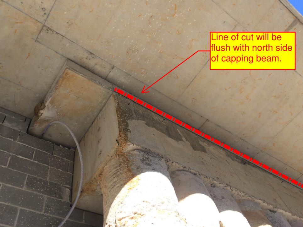
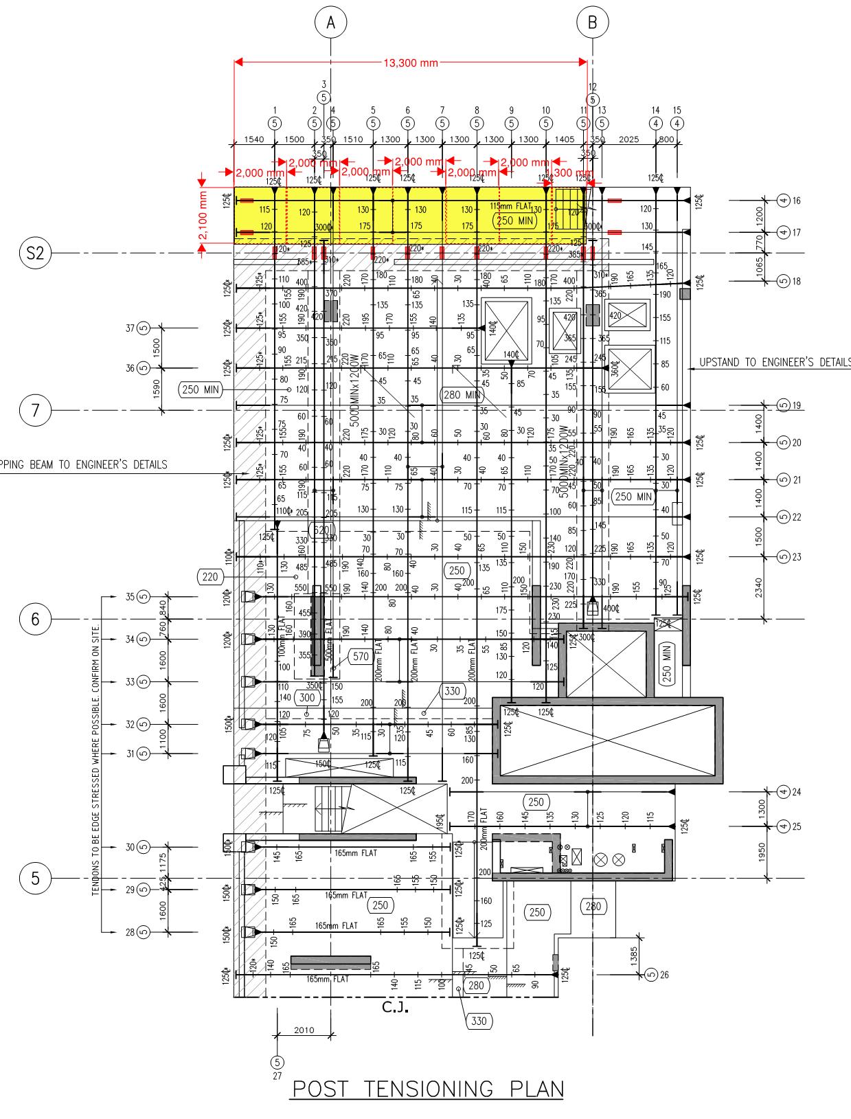
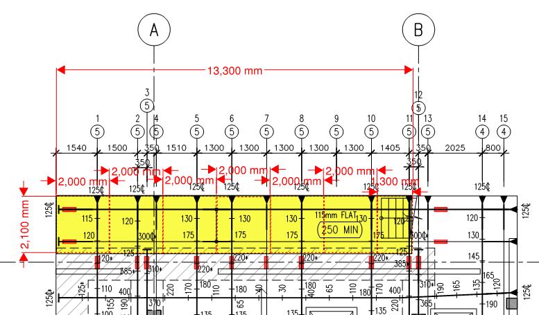
Step 3: We scanned the area to locate services and ensure PT ducts were as per the as-built drawings, they were. Step 4: Truncate the PT tendons 100mm past the line of cut (in the section of the slab remaining) to ensure the tendon remains stressed once the cut. The image below shows the entire slab, the section removed is highlighted yellow, the red rectangles represent areas of the PT duct which were truncated. A more detailed image is below it.
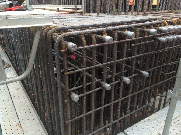
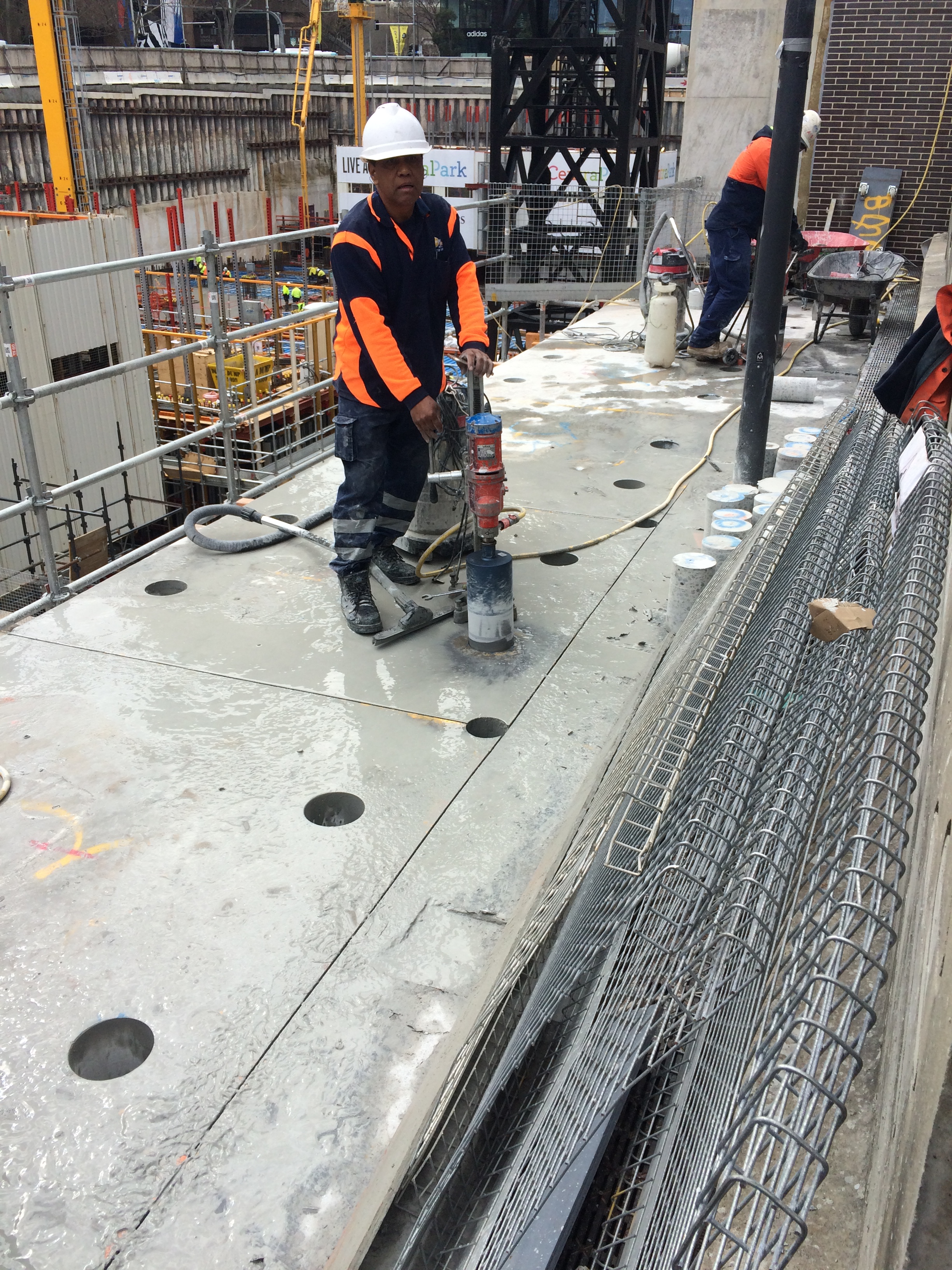
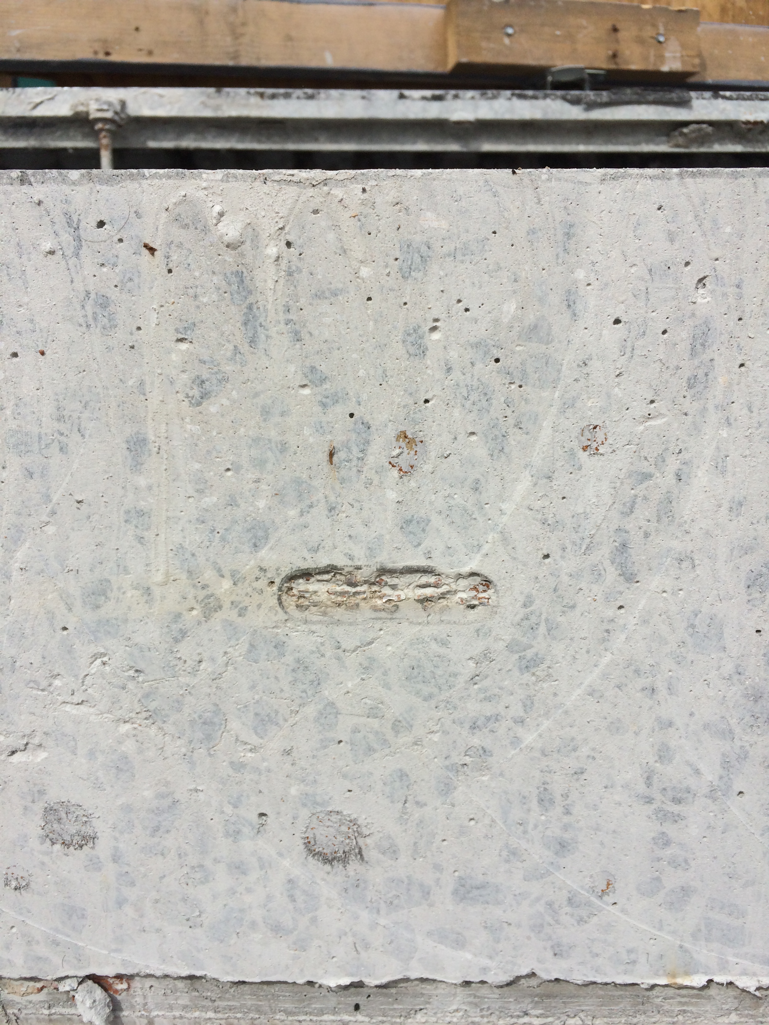
The truncation process involved removing a 500mm x 200mm by 150mm deep section of the slab to expose the PT duct, image below. The duct was then stripped back to allow inspection of the grouting around the tendons. The void was then filled with an epoxy which, once cured, acts as a plug to truncate the remaining tendon.
Step 5: Core holes were then drilled for two reasons… 1. to allow the sections to be slung by the crane crew, 2. to prevent the ‘road saw’ from over cutting at key locations.
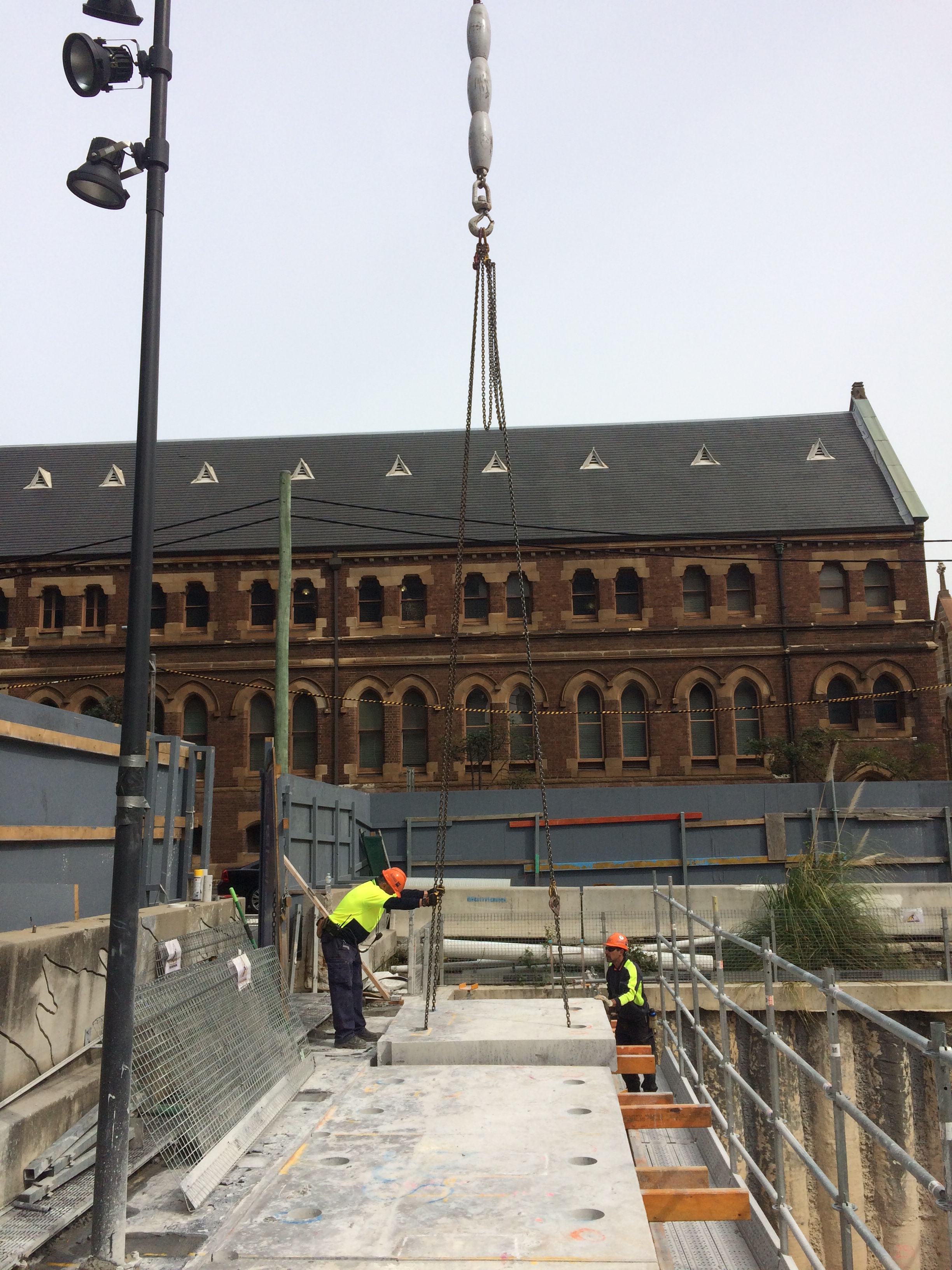
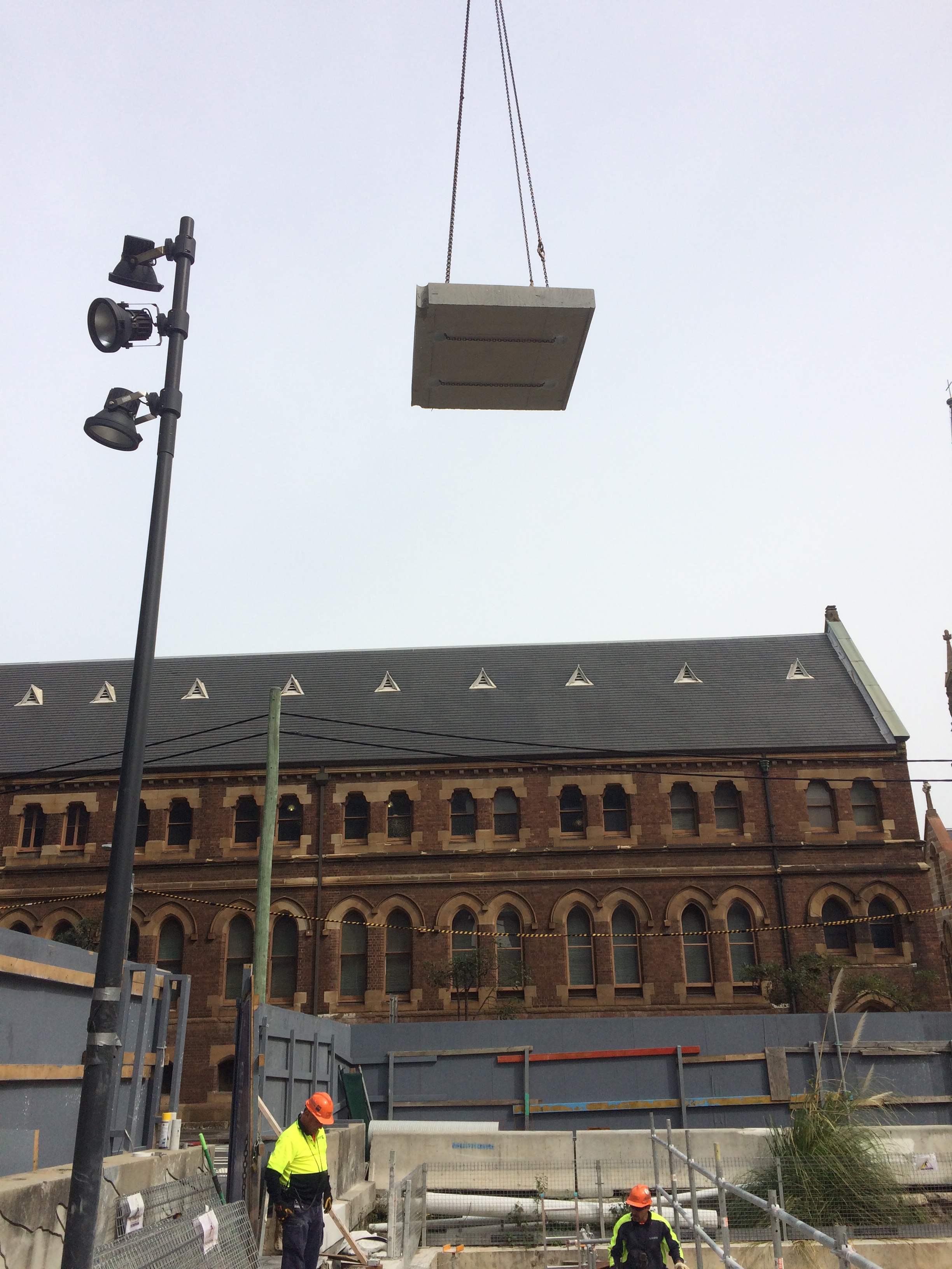
Step 6: The sections were then slung and lifted out for removal from site.
The final step involves treating the newly exposed PT tendons to prevent corrosion. On inspection we noticed that the PT tendons had slipped at 2 of the 12 epoxy plugs, one by 70mm and the other by 180mm. Initial analysis indicates that the slip is acceptable but an investigation is ongoing to work out why the slip occurred. In my opinion, it is worth noting that these two locations lacked grout around the tendons during the grout inspection. More is therefore being asked of the these epoxy plugs. It is also worth noting that the epoxy didn’t appear to be completely cured. In my opinion, these two factors are to blame for the slip, but hindsight is a wonderful thing and time is money apparently…
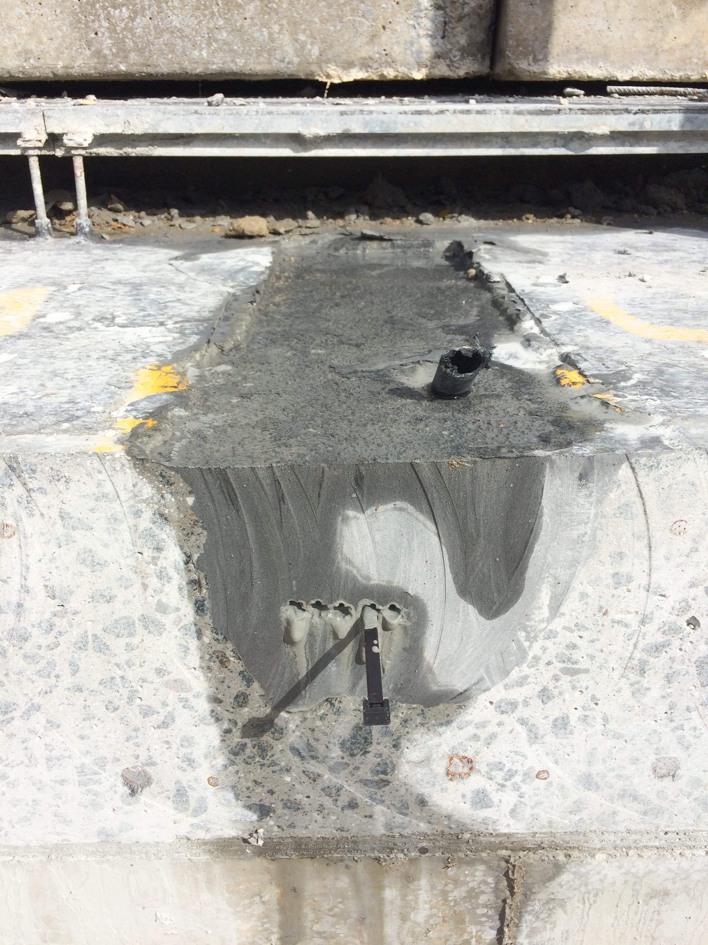
The image below shows the exposed PT tendon at the face of the cut. NB: no slip!
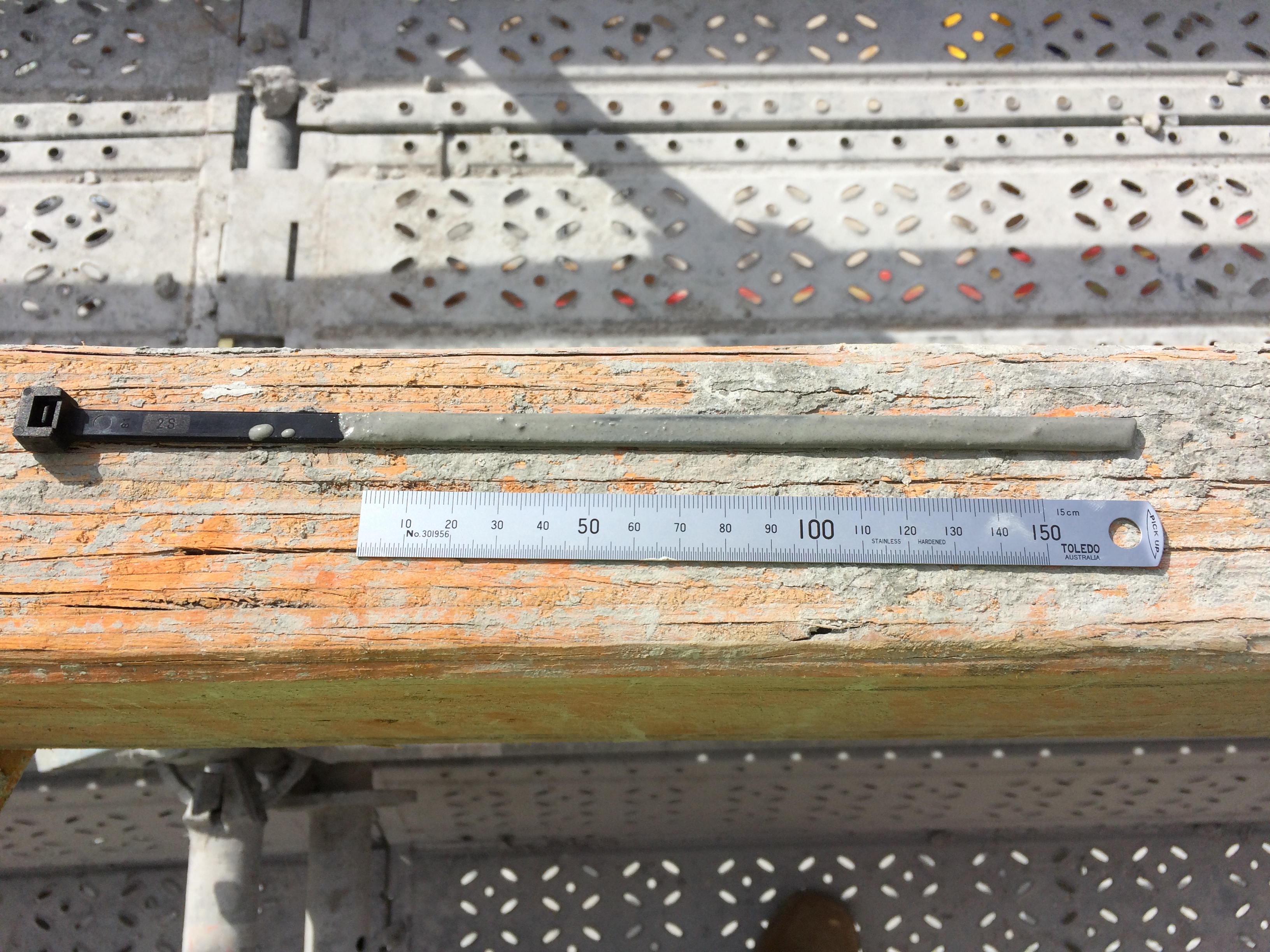
The image below shows slippage of the PT tendon at the face of the cut. NB: my high-tech cable tie measuring device!
More to follow…
Battersea Power Station Phase 3 Update
I realised I have been a blog voyeur and not participated a great deal so I thought I would provide an update.
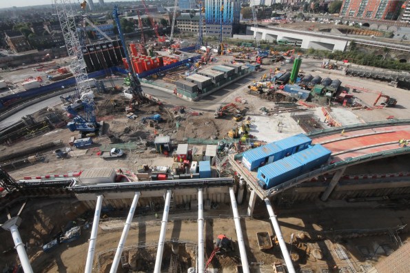
Photo 1 – Site today.
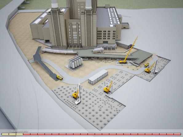
Photo 2 – My task – Bridge 1 CAD image (NB existing ramp visible on left. The existing ramp is visible from the train when travelling into Victoria).
Balfour Beatty Ground Engineering has nearly completed all piles (nearly 300) along the line of the first temporary bridge structure (area A). This has allowed McGee to commence construction of the pile caps that the bridge structure will sit upon. Points of note. Photo 3 shows Dolphins 7, 8 & 9 (the terminology for the RC sway frame that the bridge steel decking sits upon). The pile cap for dolphin 9 has been poured, the rebar for dolphin 8 is being fixed and the blinding has been poured for dolphin 7. There is over 140m^3 of concrete in the pile cap and when the excavation commences this pile cap will sit approximately 13m above formation level.
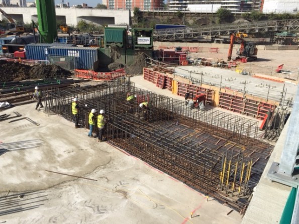
Photo 3 – View of ‘Dolphin’ 7, 8 & 9 with pile cap 9 poured, rebar for pile 8 fixed and over 40m^3 of blinding for Pile cap 7.
In tandem DAM structures have commenced fabrication of the steel deck structure and I have conducted a number of visits to East Yorkshire (‘Brid’ as the locals call it). All of the sections are ‘standard’ road haulage dimensions to avoid wide loads. The bridge deck comprises three 2.4m wide sections plus edge sections – Photo 4 shows a standard bridge deck on its side in order to weld the steel plate that makes up the road surface.
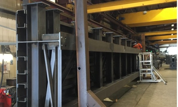
Photo 4 – Steel Deck Sections in the fabrication shop (This is a ‘normal’ deck section 2.4 m wide, 12m long and weighs approx. 13T) .
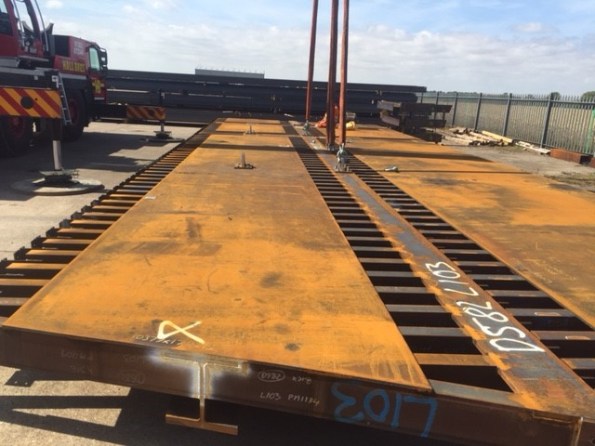
Photo 5 – Practice lift and erection in DAM Structures yard (these are special deck sections that connect to the existing permanent bridge).
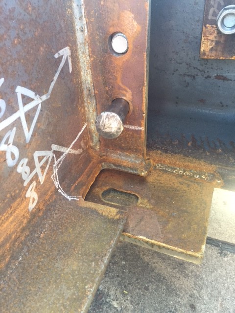
Photo 6 – Connection detail.
Interesting ‘stuff’ going on:
- Contractual wrangling is still on-going.
- Bouygues UK has not signed a contract and is moving toward a construction management role.
- BBGE has not signed either
- McGee has finally signed on the dotted line.
- We had a spate of safety issues but they pale into insignificance compared to Kukie so I will not bore you with them.
- Too many piling issues to mention from pile rig failures through to changing ground conditions and everything in between.
Bit of a long post – apologies James!
Testing & commissioning
After a long delay the Crossrail tunnel vent team have finally completed a project in my patch, all be it only a temporary installation. The temporary tunnel ventilation (TTV) was supposed to complete by the end of Jun, but was finally finished on the 18th Aug; six weeks late on a three month programme. This blog describes the issues that caused the delays and the process of testing and commissioning.
The Bond Street temporary tunnel ventilation will be in continuous operation for over 18 months and is designed to apply fresh air to the running tunnels for construction ventilation at a design rate of 200m3/sec. The four fans are now installed at the -5 level within the Bond Street station construction site. They supply fresh air to ventilate the construction works within the running tunnels.
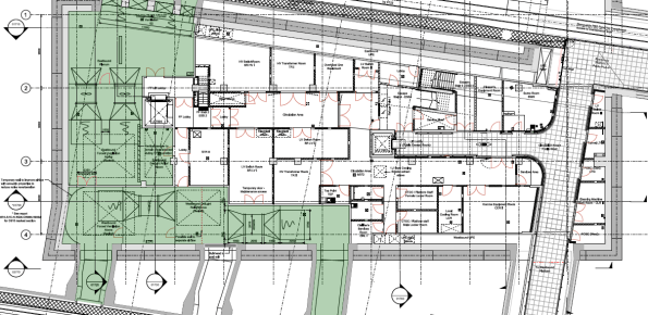
Plan view of the Bond Street Station TTV installation at the -5 level.
Despite some site access issues the mechanical install was completed to schedule. However, the station main contractor (Costain-Skanska JV) was responsible for the temporary power supply to the installation. They encountered the following delays, mostly due to poor planning and co-ordination:
- The main incomer to the site (from the District Network Operator) was installed with a different phase rotation to the rest of the site. The DNO is a law unto itself and would only come back to site to fix the problem on their terms; this relatively simple process caused CSjv a two week delay.
- The main supply cables to the fans were sized on a ‘back of fag packet’ estimate by an untrained installation contractor. The calculations were not checked by the main contractor electrical installation management. The cables ended up being undersized by about 20%; this required another 250mm2 cable to be run through the running tunnels to supply the feeder pillar, resulting in another 2 week delay.
- The temporary supply cables feeding the vent equipment were supported on the site hoarding; the weight of the cables caused the whole edifice to bow inwards towards the site. Once discovered by the site temp works co-ordinator this installation was condemned and a bespoke cable route had to be constructed. Another 4 week delay.
- The site electrical distribution protection was set to 25% of the circuit breaker (CB) rated power of 1600A. Each of the four fan motors draws 350A at full power. As a result the total power drawn was 4 x 350A = 1500A, way more than the CB setting of 400A. As the fans were run up beyond ¼ power during commissioning the CB cut the supply under load (making a sound like a bomb going off). It took another four days to find a specialist who could adjust the incomer CB to the correct setting.

The DNO searching for the phase rotation problem behind the site main transformer.
When the system was finally energised on the 16th Aug we instructed the vent installation contractor (Hargreaves Ductwork Ltd) to commission the system. Surprisingly, this was not a particularly high-tech process and followed a logical order of testing the safety systems first, then functioning of the fan motors before testing the air flow rates. The stages undertaken are outlined below:
- Emergency stop test. The fans were run up to 25% in pairs before hitting the remote emergency stops at the guardroom. No issues here.
- Fan Vibration Tests. The fan motors were started and tested for vibration using a handheld accelerometer. This measures the peak acceleration in all three axes. The peak values were recorded to compare against the readings at the first service interval in six months’ time.
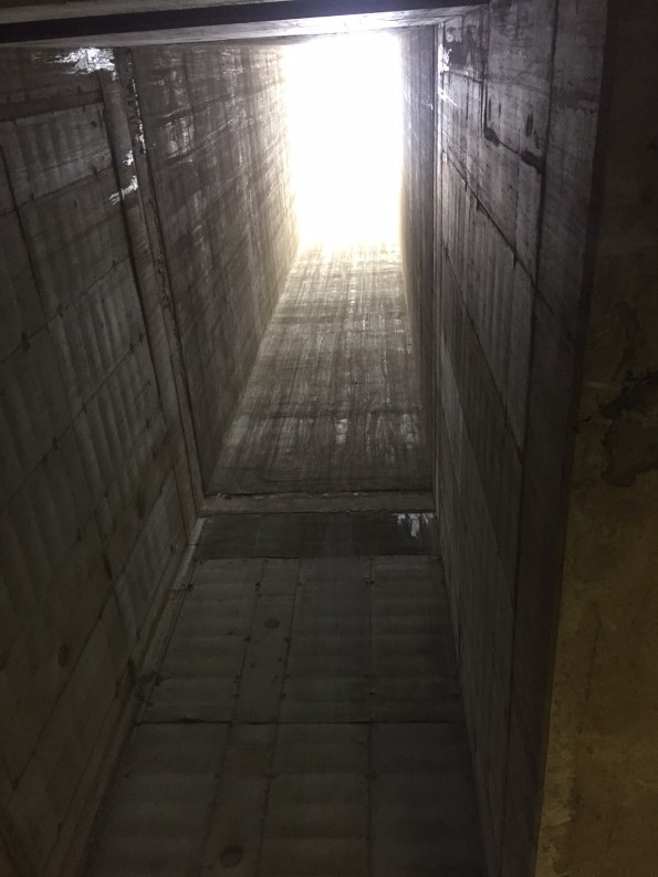
Airflow path going down through the station structure.
- Fan Air Path. The fan motors were run up through 25% increments to 100% to see if the flow created had any adverse effect on temporary works and debris in the site. At full power the air drawn in through the station was moving at 20 m/s – very windy. This flow was enough to pick up lumps insulation material from two levels above and send it through the fan blades!
- Tunnel Air Flow Rates. The airflow rates were measured from a simple average flow using a anemometer in a grid pattern in the tunnel cross-section, as illustrated in the image below.
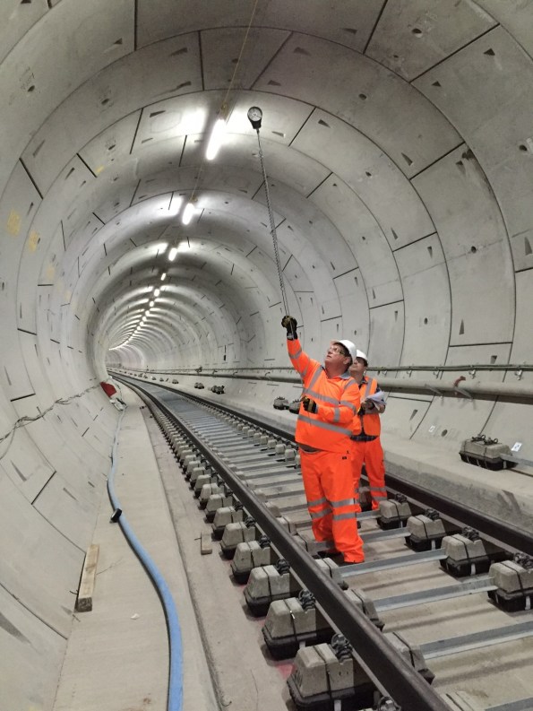
Big Ralph using the flow rate measurement grid.
Completing the T&C process marks the end of the temporary tunnel ventilation construction. The installation has been a useful dry-run for ATCjv and our sub-contractors as it has highlighted a number of issues posed by working in an underground site and within the rigid Crossrail quality control procedures. These issues can now be anticipated for the larger scale permanent ventilation installation that is currently ongoing.
On another note is hasn’t been all work and no play. Gary Jackson and I entered a navigation competition in an RAF aircraft and won it! The prize was presented by the Duke of Edinburgh, see below. Most importantly the event included a free bar…

Big Phil presenting a big prize.
Plinths for MSBs
Not the most exciting blog from me, but any assistance would be appreciated. Has anyone dealt with plinths for mechanical switch boards (MSB)? They are all being installed in ground level plant rooms of a sports stadium – some of which house AHUs and significant ‘wet’ pipework. Having dug into the specifications, there appears to be no requirement…?
That said, I presume it would good engineering practice to install a concrete plinth to aid installation, routine maintenance and prevent damage.
