Level of Learning: Conscience Incompetent
Following a good week in the office last week, I am starting to understand BP, Projects & Modifications and my role within it; here’s a flavour.
Ground
BP North sea operations currently own 6 assets in the North Sea. Bruce, Claire, Magnus, Andrew, Foinaven and Eastern Trough Area Project (ETAP), which are a mixture of single and double, steel jacket design platforms, with or without multiple subsea wells connected to the processing platform, with Foinaven being a Floating, production, Storing and Offloading (FPSO) vessel. It is the hub which covers ETAP that I have been assigned to.
Eastern Trough Area Project (ETAP) is an integrated project consisting of 9 independent reservoirs (each containing one or more well heads), 6 owned by BP and 3 by Shell, all linked to a central Processing platform. Considerably different from what a layman might consider a ‘standard’ single well, steel legged rig; the truth is there doesn’t seem to be a standard, with each of the 6 BP North Sea assets different from the next.
The diagram below shows the layout of ETAP. The main structure consists of a Processing, drilling and Raising (PdR) platform connected to a Quarters & Utilities (QU) platform, separated for safety. The Marnock well is directly below the PdR platform, with Monas, Mirren, Machar and Madoes (and Shell Egret, Skva & Heron) all being subsea wells, tied back to the Central Processing platform (CPP). The 6th BP well, Mungo, requires a Normally Unmanned Installation (NUI) in order to carry out additional processes on top of what is required for the other subsea reservoirs.

ETAP Schematic
The picture below shows the QU platform on the left, consisting of a heli deck above the accommodation and welfare facilities, power generation units (gas turbines) and other services, connected to the PdR in the centre. The structure on the right is a Flotel, which provides additional Person on Board (POB) capacity when required (i.e. during construction or Turn-A-Round (TAR)).

ETAP QU & PDR platform with Flotel
Organisation
As mentioned earlier, I am assigned to a hub which currently only deals with ETAP (and Mungo), although asset responsibilities often move between hubs depending on workload, personnel and suitability. The 3 or 4 hubs (again remaining flexible) all work within the Projects and Modifications branch of Engineering Services, which itself lies within BP Global Operations Organisation, comparable, I guess, to a TLB in the MOD.
The main role of the Project and Modifications team is in the title. It doesn’t deal with well drilling or new platform construction (these are dealt with by Global Wells Organisation and Global Projects Organisation (other TLBs)) but instead deal with any routine or emergency upgrades, additions or repairs, primarily to enhance safety or production, up to a value of $15m.
Contract
A contract was renewed this year with Wood Group PSN (WGPSN) called BP Focus, which is a 5 year contract (with a 2 year extension option), which covers Upstream (offshore assets) and midstream (onshore processing) on a cost reimbursement + basis. WGPSN primarily only deal with the latter stages of the project lifecycle, (Define & Execute), with the earlier stages, (Appraise & Select), being delivered by Costain. Again, remain flexible.
The Cost reimbursement + contract means that WGPSN invoice BP for all direct costs incurred, due to general overheads and any work carried out on the specific projects. Added to this is a fixed mark-up percentage, the value of which depends on the cost element but as an example is 6% for ‘Real estate services, desk space, phones etc and up to 8% for personnel. In addition, there is an incentive scheme which offers a bonus of up to 4% against some of the cost elements, primarily personnel if a project meets certain Key Performance Indicators (KPIs) which are agreed annually.
My Role
As a Project Engineer, I am the Single Point of Accountability (SPA) for a number of projects on ETAP. My role is to liaise with the appropriate team within WGPSN and monitor the development throughout each of the project lifecycle phases, engaging with BP staff, WGPSN staff and external agencies as required in order to move the project forward. Budgets and scheduling are key, and it will be my responsibility to ensure that timings are adhered to, budgets are realistic and monitored, whilst constantly feeding this back to the BP side to ensure there is one version of the truth. The BP Method of Change (MoC) process which is there to help identify, assess, manage and communicate risk throughout the project lifecycle also needs to be managed, to ensure the correct processes are being followed and that all relevant documents are up to date and easily accessible. This along with other key documents will form the basis of a go/no go decision at key points along the project life cycle either between phases or at the 12, 6 or 2 week review before the project is executed offshore.
Clearly this is an attempt to summarise in a paragraph what I am meant to be doing, having had very little experience to date; talking to Brendan and Nick, it is clear it is not as simple as it sounds and only be doing it will I get a thorough understanding. My next blog will explain a project I have just taken over, which should hopefully provide some clarity on all the above.
Key points to take away: The military are just amateurs when it comes to TLAs and flexibility is key!
Other news
Pregnancy – Still
New house – aim for contract exchange this Friday, completion next week.
Just been along to a meeting at my local BSAC dive club, looking forward to some off shore diving soon.
Developing
Being positioned away from London clearly Brad and I will be unable to get to any of the evening Institution lectures to broaden our scope as Engineers prior to professional review. Enter USACE’s Officer Professional Development (OPD) programme to fill that gap. The current programme to gather Baltimore District’s 15 military members is quarterly meetings of a day and an annual 3 day trip. This year’s 3 day bender centred around the civil works programme within the Baltimore District, more specifically on the restoration and maintenance of the Chesapeake Bay. Below is a quick canter through the challenge presented to USACE:
However, before the learning, the programme started with a PFA and Howard had instructed us that it was ‘tradition’ to make sure the superpower was kept in check. So after a nervous start a Brit 1, 3 was achieved; we also managed to avoid embarrassment in the later ‘Ultimate Football’ game; end to end exhausting fun.

After round 1 didn’t go their way we had to play with this funny rugby ball
Chesapeake Bay
When America was colonised the Chesapeake Bay and surrounding area were some of the first places that the settlers put down roots due to the abundance of seafood in the bay and the favourable conditions for shipping of a sheltered deep harbour. As Richard indicated during our river and flooding day in Chatham however, the impacts of firstly the Royal Engineers and later USACE building dams and developing farmland have, alongside over fishing changed the landscape. Now Maryland state must ensure that the bay now supports the industries (shipping and fishing) that have grown up within it as well as be environmentally sustainable.
Shipping is one of Baltimore’s biggest industries as it has one of only 2 ports on the Eastern Seaboard that can receive ‘Super Panama Tankers’ which require a 50’ channel. This is as a result of dredging channels and, despite biting the hand that feeds it; Maryland state law presents some difficulties to the disposal of the dredged material. Dredged material can’t be dumped in the open water of the Chesapeake Bay and new islands can’t be created within the State’s waters. Additionally all the material in the habour is considered contaminated (with heavy metals etc) potentially causing water pollution when disturbed.
Being America clearly the numbers are big: 4.5 million cubic yards (the volume of 1.5 football stadiums) per year of sediment needs to be removed from the bay channels for maintenance alone. It is 180 miles from Baltimore Harbour to the mouth of the Chesapeake and the Atlantic Ocean where the first open water dumping ground would be; this would be expensive so they don’t do it. Instead the solution is land reclamation, either extending peninsulas or enlarging islands, and as the dredged material looked as if it had all the structural properties of a soggy blancmange the land is mainly used to build nature reserves and still isn’t cheap.

The scale of the Chesapeake Bay
The current main destination is Poplar Island, which over the last 20 years has taken approximately 100 million cubic yards at a cost of $1 billion, so $10 per cubic yard, or $50 million a year. The engineering is pretty simple; build berm from sand etc, put in loch gate to drain out water, pump dredged material (80% water, 20% solids), let it settle and drain the excess water. Of greater complexity are getting the water quality to the acceptable standard to drain into the Chesapeake Bay, introducing plant species to be beneficial for wildlife and hold the island together and the liability USACE will have for the island once completed.
They are planning on handing the National Parks Service (NPS) as a nature reserve. However, the maintenance of islands made from contaminated dredged material isn’t the NPS’s Mastermind special round choice and so USACE will still be responsible, and liable, for ensuring the island maintains its integrity. Clearly in the grand scheme of things with both parties being Government departments it is merely the department best positioned to deal with the issue being responsible which is best for the Nation and Government but that philosophy is muddied by departmental budgets and politics.
Other elements of note were the Conowingo Dam on the Susquehanna river is now ‘full’ of silt which is going to result in more being transported down stream and into the Bay. This is again an area of liability controversy as it was built by USACE, in 1926, but is now operated by Susquehanna Electric Company (SEC). Clearly neither want to accept liability and pay the exorbitant dredging costs, though ultimately SEC has the upper hand as if they don’t deal with it behind the dam then the problem will get passed on to USACE when the silt hits the bay. From an E&M perspective, more interesting than the silt was 1950’s style sign, below.
Also the rare forethought of the 1920’s designer who foresaw the increasing need for electricity and built space for an extra 4 turbines over the 7 installed at commissioning. The original 7 turbines produced 250 MW of power, in the 1960’s the remaining 4 were installed with equal power output giving the dam an output of 500MW.

The very 1950’s sign and the 1960’s turbines.
Site Two Fifty One – In the thick of It
Site Two Fifty One – In the Thick of It.

Capping beam steel erection.
I have mentioned before that one of my roles is the installation of the capping beam which runs the full perimeter of my site (180m). The steel for the first 35m arrived on Monday to culminate a design development of something I have been responsible for since arrival. The capping beam will have an in-situ wall sitting on it and a basement slab spanning from it. Additionally, for about 5 months, it will be used as a beam to prop off in order to excavate one storey down.
Groundforce propping plan (click to open pdf): 1728 101
So there are elements to the installation which have huge consequences if not correct.
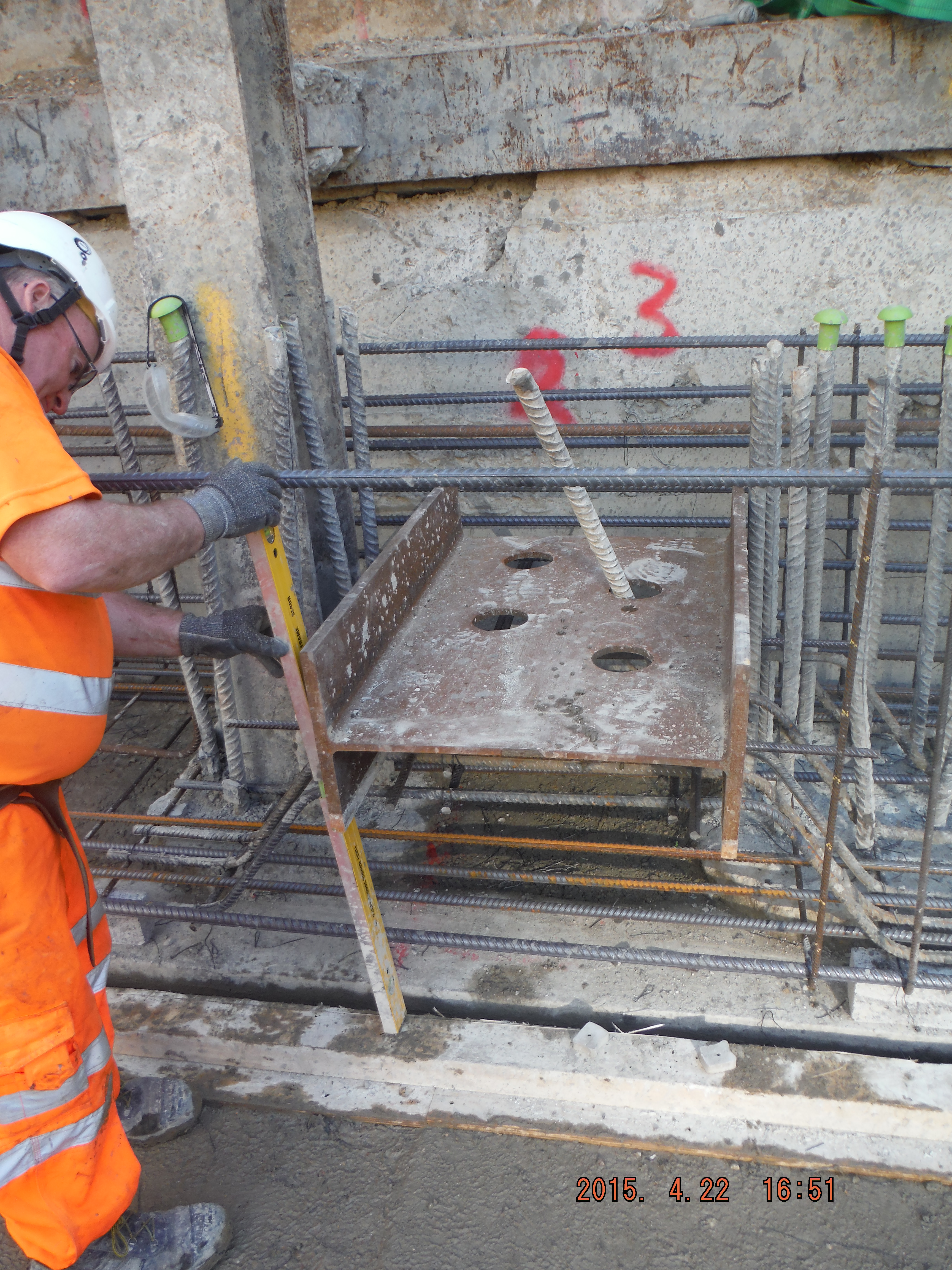
Single shear stub.
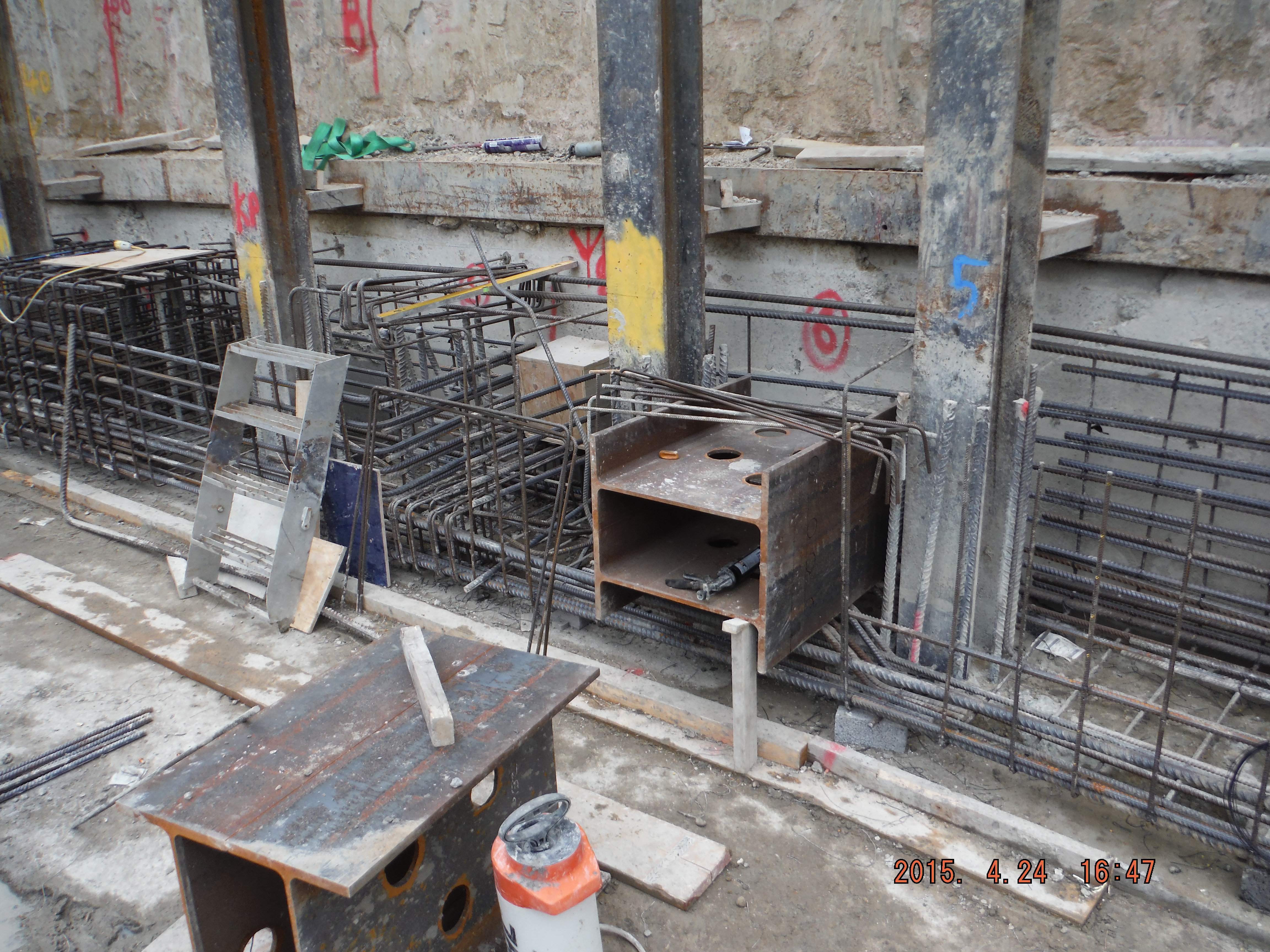
Double shear stub.
There is a drainage duct which protrudes through the beam and there are umpteen ‘king posts’ column sections retaining the old retaining wall behind.


Drainage pipe location (left). Bent bars around drainage position (right).
All in all, there is lots going on. The capping beam steel has been digitally modelled, which has 2 advantages. 1. It helps understand how it fits together and 2. The steel schedules are produced from it (Tekla software) which can be used directly by the steel supplier, rather than a person re-typing a pdf document.
As a task, perhaps initially seemingly pretty minor, there are actually numerous considerations:
- Sourcing of steel (Laing O’Rourke will only purchase from Europe although many steel suppliers source from China because it’s cheaper).
- Delivery method: pre-slung or stacked for slinging on site. Method of lifting (crane, excavator), LOAFs.
- Length of bars for working in congested areas (more lapping versus ease of installation).
- Stop ends (max pour size is 40m3.) Use of hirib to avoid scabbling.
- Prop end plate locations and bolt hole positions.
- Formwork design (yes concrete pressures for a 1.2 high beam is important).
- Resource management (lead times, timber, concrete, steel, tools and equipment)
- Concrete – waterproofing.
- Future slab starter bars (kwika-strip).
- Labour management (steel fixers, carpenters, labourers).
- Dewatering (bottom of blinding is at ground water level): sump pumps, discharge permits, siltbusters.
- Concurrent adjacent activities: sheet piling, CFA piling, muck away, welfare establishment, ramp movement).
Reflections.
So far so good, just. It is pretty much construction by just in time design. This means I am getting drawings hours (sometimes minutes) before they are needed on site. This means being familiar with bar mark notation, real detail in why shear links are here or there is key. In reality there are good people to answer my RFIs (temporary works department, Groundforce shorco, digital engineers, steel supplier (Midland Steel), the designers (Waterman)) but there are always pressures to deal with on site. Line and level of shear stubs for props, drainage duct location and invert levels and actual position of the capping beam itself.
It is hugely rewarding to see something you have been involved in start come to fruition, albeit the first big test will be my shuttering design! The concrete pour is planned for next week so no doubt the grey stuff will soon feature.
I think running the execution of the capping beam is a great chance to learn how things work before the significant challenge of the basement slab (entire site) comes along.
In other news, there has been the first working load test on the office piles and a section of site has had sheet piles installed to act as a replacement retaining wall (where the old substation was).

Pile working load test (as Pete predicted!). No further details yet.
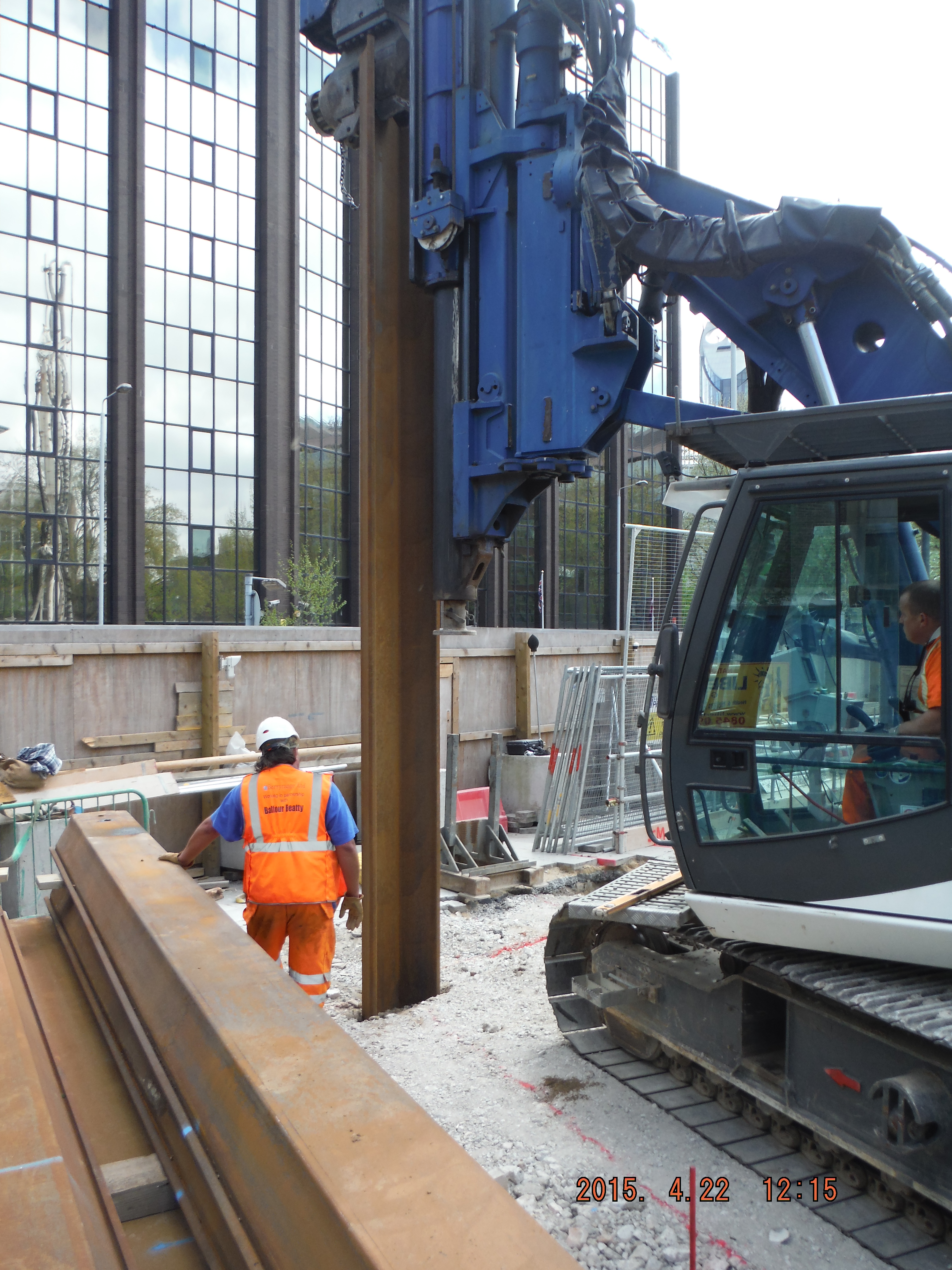
Rotary bored (tick), CFA (tick) and now a bit of vibratory sheet piling.
Risk free plumbing
Since the sub-contractor went into administration a couple of weeks ago their sub-sub-contractors and suppliers have been either walking off site (like the plumbers), or going straight to McAlpine in order to get paid.
We are now paying for:
Steel
Plumbers
Drainage stores
Skips
Waterproofing materials
Timber and consumables
Muck-away
Almost everything else
PC Harrington are still paying for:
Concrete
Some labour
The drainage is now being installed by Realtime. Since we needed them to start immediately they had us over a barrel at least initially so they’re currently working on day rates. A price will be agreed soon but in the mean time they’re making hay while the sun’s shining. The contractor is throwing blokes at the job, which is great for our progress and great for his profit. We pay £31 per hour for the drainage supervisor. He probably earns half that at best. The rest is overheads and profit. They are working totally risk free.
More concerning is that we’re having to supply timber and consumables. Even B&Q won’t give PC Harrington any credit! We’re also now supplying pull-out bars for the slipform. Irritatingly they’re on a 1 week lead time. We were only told they couldn’t get them yesterday, but they need them tomorrow. Obviously this can’t be done. We asked for the quantities and we’re told the engineer would do the take off for us. This means they hadn’t done the take off. That means not only had they not placed the order themselves, but they had no intention of doing so.
In a progress meeting yesterday PC Harrington told us that their recovery program would be issued 48 hours late. They can’t even program when their program will be published. They also gave us a list of what works they will complete in the next two weeks. They told us how far behind they are today but had no idea how they would be looking in two weeks time. Their forward planning is terrible.
There are some great things about working in civvi street: they are very efficient and know their stuff, the other day I was running late and didn’t shave before work, no one cared that I wouldn’t be able to get a proper seal with a respirator!
There is also some really annoying stuff. The accuracy of their written work is terrible. If I have to read another ITP describing me as a Mace representative when I work for McAlpine I might scream! And their ability to plan beyond what their having for lunch is woeful. I use to laugh at the term “military precision” having seen some pretty slap dash planning, but at least it was planned, which is a start!
Rant over.
UPDATE – We are now also buying their stationary. Today we had an order for 30 reams of A4 paper!
Oh how I long for Eurocodes!!!
I never thought I’d say this, but I really do long for Eurocodes. Whilst the plethora of EC books for design exercises in Phase 1 may have seemed confusing, whilst being in the USACE office I now realise just how thorough and user friendly they all were. I can almost picture (longingly) the flow charts we used for steel design.
Instead, I am presently hamstrung by a Steel Construction and Design Manual (SCDM) that is 3 inches thick and literally made of cigarette paper. Not only is there no easy flow to the manual and its contents, but it sits in isolation with no sponsored design examples. Instead there are a plethora of Design Guides that are not up to date, therefore do not reference the SCDM accurately. In some case, such as one of my projects (a supporting structure design for overhead cranes), US structural engineers use a Canadian design guide that is more thorough…and to add injury to insult, it uses metric units rather than imperial! Added to that is the choice of which design philosophy to use, and the one you have decided to use may not be the one that the Design Guide explains and/or uses in its design examples. That said, though my design calculations seem to take an inordinate amount of time for me to consistently detangle my knickers, it has forced me to go back to first principles!
Two design philosophies exist in the USA: Allowable Strength Design (ASD) and Load and Resistance Factor Design (LRFD). Both are strength based philosophies, though ASD was historically stress based. My first question was: What on earth is the difference and which one do I use?
1. When considering the steel yield vs displacement graph, the combined force levels (i.e. load, moment shear) for ASD design are kept below Fy, by taking the nominal strength Fu and dividing it by a factor of safety (aka permissible stress design). For LRFD, the combined force levels are kept below a ‘computed’ member load capacity which is a product of Fu multiplied by a resistance factor (aka limit state design ~ Eurocodes!).
2. ASD treats live and dead loads equally, thus uses one FOS for both live and dead loads – this accounts for uncertainty in load and capacity. Consequently it is simpler to use and more conservative. LRFD however recognises the inconsistencies of dead and live loads thus allocates a higher FOS for live loads than dead loads as dead loads are believed to be more accurately calculated…. LRFD also recognises inconsistencies in material properties and construction tolerances.
So, though LRFD is proven to be a more ‘efficient’ approach in that it harnesses more of the strength capacity of a member, legally we can use either method for steel frame design. ASD has historically been significantly quicker than LRFD for preliminary design although recent editions of SCDM have become more thorough for ASD. I honestly believe that having uses ASD, it appears quicker than LRFD (not that I have done the latter yet) but it is still far slower than EC….largely due to the complexity of the Design ManuaI (and because imperial units are driving me insane!) And that is the reason that every engineer has told me why old-school US structural engineers are steering well clear of adopting LRFD (not the units piece).
The same goes for timber and masonry design; concrete is the only one where LRFD is mandated (by the ACI). But to add even more confusion, USACE has mandated LRFD for certain design work such as hydraulic steel structures. Then, I have also found, that product catalogues will vary in what methodology they have used for their allowable loads – this makes things incredibly tedious. All in all a disjointed approach across all the institutions!
BIM continued – FAIL
As previously mentioned our BIM set-up is more targeted at data collection than actual collaborative working and as a result we lack many of the real benefits BIM has to offer.
Our river wall consists of a 16m deep sheet pile wall that is paralleled by a 6m anchor wall. The two are tied together by 63.5mm bars (dwg below). This was installed a couple of months ago.
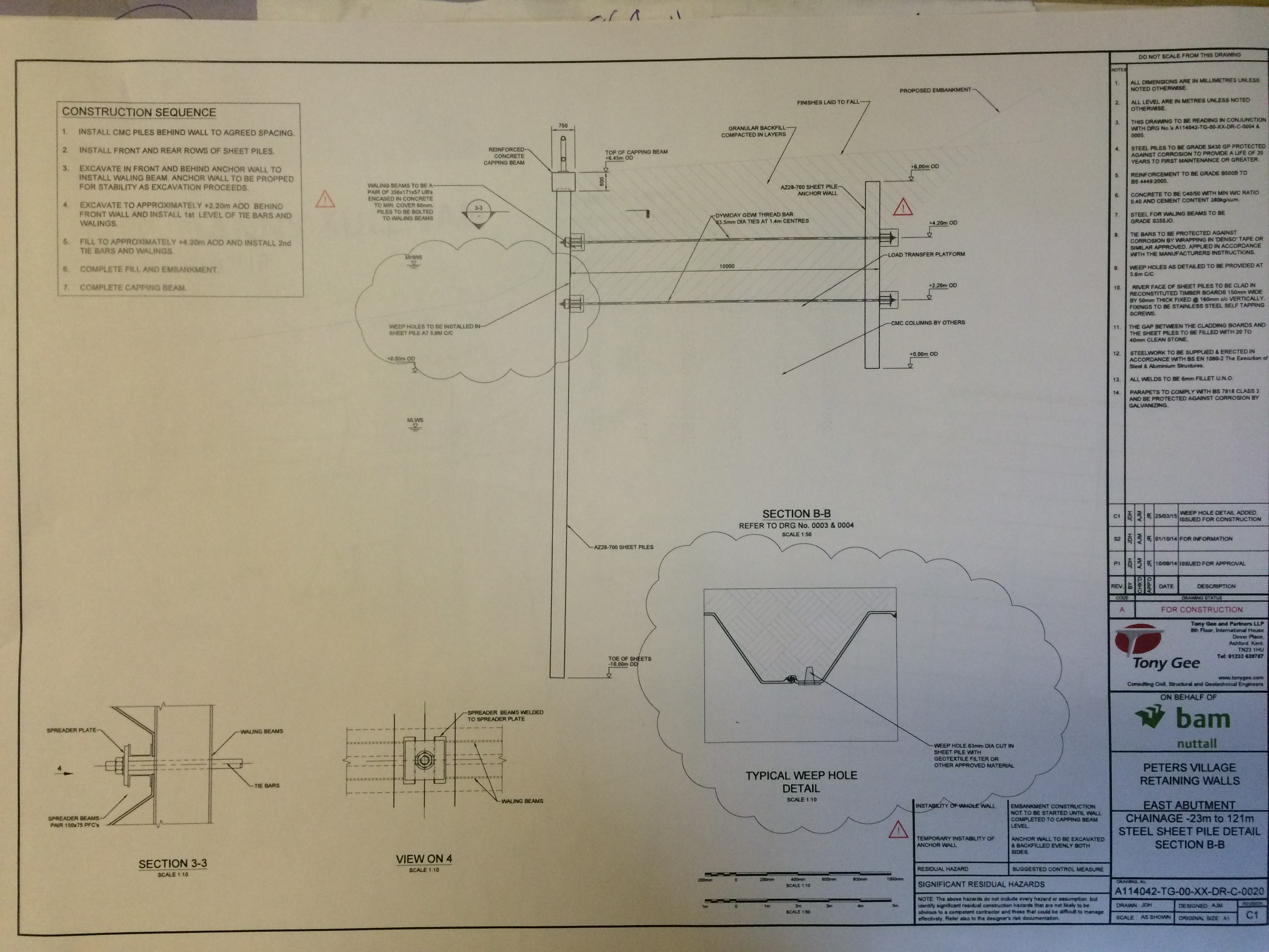
River and anchor wall design
Yesterday our piling contractor hit one of the tie rod sticking out of the back of the anchor wall.

6m deep, tie rod visible on the left of next to the light.
The sheet wall and piling scheme designers are different and neither of these are our principal designer. We are now in the process of getting the pile location redesigned. Hopefully the designer confirms the coordinate change in a couple of days otherwise the piling gang will be stood at a cost of £6k/day. Whilst I’m not going to get in to the specific details it is fair to say that collaborative working would have gone a long way to prevent this form happening.
So…
What is the better approach, setting up an expensive system and enforcing it or paying to fix problems when they arise?
Lang time nae see, Far hiv ye been, min?
It’s now the start of my third week at BP and although I’ve not really got into the detail of what I will be doing and be responsible for, I thought I would summarise what I have done to date and offer an anecdote or two. A separate post will follow on BP, the contract and my role, in due course.
Safety, Safety, Safety
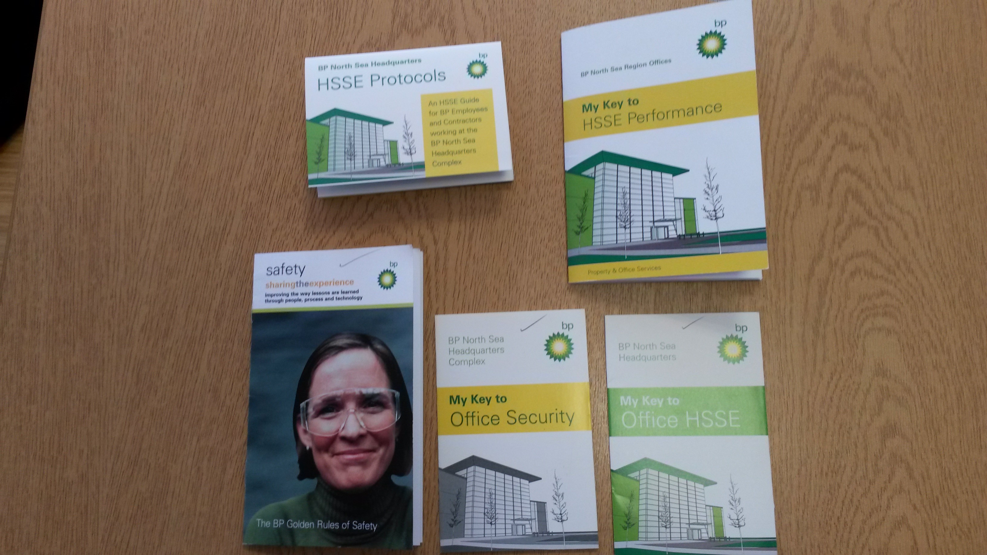
It’s a bit of an eye opener, exactly how safety conscious BP, and indeed the wider oil & gas industry are. I have had to do two inductions as you might expect, one for each of the buildings I will be working in. The Wood Group PSN induction was a fairly straight forward video, which lasted 15 mins or so, the BP induction lasted a little under an hour, at the end of which I received the guides shown below. The main document (top right) has 23 pages, each of which either presents critical information, directs you to read one of the other documents or asks you to carry our further reading / action, which all require a signature; this is then followed up by the second part of the induction process.
A bit over the top for an office environment? My opinion is not. (you may be surprised by that). What it does, is make you understand just how seriously they take your health & safety and drum this into you from the start, reinforcing the company values of ‘No accidents, No harm to people, No damage to the environment’. (try sitting at Costa in the Union Square shopping centre in Aberdeen; you’ll easily be able to identify those in the industry – they are the ones who walk up the stairs on the left and hold the hand rail)
The place where H&S is absolutely vital is of course off shore on one of the installations. To that end, last week, I completed the Basic Offshore Safety Induction & Emergency Training (BOSIET), Compressed Air Emergency Breathing Apparatus Course (CA-EBA) and the Minimum Industry Safety Training (MIST). The BOSIET Cse was probably the most interesting as it goes through the different types of offshore installation, how to survive in water and in a life raft, firefighting, basic first aid and of course the heli dunking; good value. MIST had some value and added to training already completed at the RSME and previously. (Offshore regulations, Fire, Risk matrix, permit to work etc)
Process, Process, Process
BP appears to have a very defined and slick process for everything they do; the most obvious is their Management of Change (MoC) process. This is supported by an online application which groups together information and documentation for any individual project from the screening phase all the way through to hand over, with great usable features including automatic email updates, assignment of responsibilities and go/no go gates.
They also appear to be very swept up in dealing with Information Management (IM) using their Intranet sites to good effect; I certainly spent a lot of time in my first week reading the various areas and has been useful whilst writing AER1.
Notice that I used the word ‘appear’ in both those paragraphs; I’m sure time will tell if it is as good as it looks or if it will be comparable to JPA, SPOC, MOSS et al.
Money, Money, Money
It’s eye watering looking at the costs of what seem to be simple projects. I will make this a separate post in the future, once it is fully understood as it’s deserving of its own blog.
In other news
Aberdeen is a great city – Would certainly consider living here
Charlotte is still pregnant (27 weeks) and don’t I know it!
Still waiting to move into new house (in London) and preparing for our DIY(ish) ‘Grand Design’
For future BP attach-mentees: I am preparing a 3-4 pager ‘Get you in’ Admin Instr to summarise the last few months of admin points, similar to the AUS document, but clearly a lot simpler. This will be stored on the RMSE servers. Additional documents (initial actions and HO/TO notes) will then be available on arrival which have been passed on from previous courses.
BIM – Bureaucracy or Beneficial
There is no public investment into the Peters Village project and the last time I checked it was not 2016, therefore we are not at liberty to conform to any governmental BIM direction. That being said we are aspiring to collate all of the project data centrally and utilise technology to increase efficiency at an engineering and management level.
So is it working?
The Good – We have a BIM co-ordinator, a cloud based server, lots of drawings and 3D models. We have iPads with more auto-syncd forms than you would ever need and the ability to capture any media file type and link it to technical information. There is a data base that allows you to see (with permission) the commercial files, drawings, specifications, programmes, plant and materials lists on your phone if you so desire.
The Bad – The engineering check list and QA forms are on Autodesk BIM 306 on the ipads but the filing system is overly complex. The cloud based system is different to BIM 360. We have multiple designers who are using different CAD co-ords so dwgs need aligning. The designers are mostly sending through drawings in pdf format and not as part of a master CAD dwg. The cloud based servers is provided through a satellite link on the East Site compound and boosted over the river (very unstable). Whilst the cloud based system allows access anywhere, the system to upload and download files reminds me of the pain I went through trying to submit AER1. On and on…
The Ugly…Truth – The aspiration is commendable, one central log of information, accessible by all, from anywhere, anytime. The reality is multiple databases holding vast quantities of unrefined information. This is not as a result of lack of ambition but rather lack of training, man power and strategy. Those driving BIM are double hatted and unable to dedicate themselves to it, also they seem to lack the full support of the wider workforce.
BIM carries a high price tag and requires considerable effort to establish the required processes. Early set up and buy in are key, without them the whole process becomes a clunky digital filing system with increased vulnerabilities and lacks the ability to assist with increasing efficiencies. I find myself wondering if the system we have in place has actually brought about improvements of if it has over complicated things.
Growing Tomatoes in the Desert
This blog aims to give a brief overview of the project I am working on here in Port Augusta, along with progress to date and key risks/issues identified by John Holland Group (JHG).
The Project
The overall aim of the project is to produce a year –round sustainable horticultural products for the Australia’s national grocery market and to do so with minimal fossil fuel usage and no extraction of fresh water from the environment. To achieve this the project will incorporate a solar energy collection system that is designed to heat water for thermal energy storage and use. The hot water is then used to distil freshwater from sea water and heat the greenhouse in cold conditions. The excess steam produced is used to drive a steam turbine and generator. The greenhouses alone will cover 20ha and the tower will be 115m. This system is simplified below:

The Site
The site is in the bush, approximately 12km South of Port Augusta. For those of you unaware of Port Augusta, it is classified as a major city in South Australia, but with a population of around 13000, think more like small town. It is situated about 300km north of Adelaide at the head of the Spencer Gulf and it is a bit of a crossroads town, with the main communication lines (rail and road) linking North/South and East/West crossing here. The site was selected as the area has a warm desert climate, with low humidity and sun almost every day of the year. (Although this week work on site was suspended as 33mm of rain fell in 12 hours).

Contract
The contract is an Engineering, Procurement and Construct (EPC) which is the same as a Design and Build Contract. It was awarded to JHG on 1 Dec 14, with ground works beginning just two weeks later currently the project is due for completion in Oct 16.
As this an EPC contract the final cost ($168 million) of the project has already been agreed with the client and finances secured from an investor. In order to secure this finance the client was forced to appoint a main contractor to manage the whole project, additionally the amount of finance is the upper limit, therefore there is no scope for change on the client’s behalf, without having to find savings elsewhere within the project, and this again is identified as a key risk by John Holland Group (JHG).
The majority of subcontractors have already been selected for the construction and have been used in the detailed design stage, and are listed below:
Civil works – York Civil
Greenhouses – Van Der Hoven
Power Generation – AALBERG
Balance of Plant – KBR
Electrical – TBC
Risks
One of the key risks identified by JHG is the interface between each of the subcontractor elements, in particular the E&M elements. In addition because several of the subcontractors are new to working with a main contractor there are concerns over the difference in perceptions and procedures, especially in regards to risk management and planning. As an example, last week two loads of concrete had to be turned around from site; Van Der Hoven had ordered it for the foundations for the first greenhouse, however they had not submitted Inspection and Testing Plans, thus no one from JHG had inspected the foundations. In addition the delivery had not been briefed during the pre-start, therefore none of the plant operating on site knew about it, raising issues about safety. By the time inspections had been made, the concrete had been sitting there too long and was rejected. Clearly there are also various environmental risks when working on a site in the middle of the bush:


Progress to Date
So far the ground works have been the focus, laying out of the first greenhouse is now taking place and the foundations dug. So far JHG representation on site has been limited to around 5 personnel, this is changing at the moment with someone new turning up almost every day, and a new project manager (Former Royal Engineer Mark Burnett OBE) is due in the next couple of weeks. With this influx of personnel the organisational structure and roles and responsibilities on site is changing daily, with the new project manager hopefully this will stabilise. My role within the project is still up for debate, with various people offering up opinions, but confirmation TBC. So far similar to Rich I have been reading various contracts, attending meetings with stakeholders and getting to know the JHG procedures.
At least they got the specification of the biscuits sorted…
As promised last week, this blog will aim to outline what my role will entail, detail the main challenges associated with the project and highlight some issues that I’ve already come across.
Job role
I’ve been given the job title of Building Services Manager and as I mentioned last week I am being given responsibility for the services in the basement; although it looks like I’m going to be shadowing the principal building services manager whilst I earn my spurs. The M&E services within phase 1 are being delivered by one main sub-contractor, Skanska. My role will involve setting benchmarks for different areas / services within the basement and ensuring these are complied with, reviewing & approving risk assessments and method statement (RAMS) and conducting Inspection and Testing Plans (ITPs). There will also be an element of facilitating Skanska’s work within the basement and coordinating with Carillion’s project manager for the basement. Any feedback from the PEW staff or cse 55 on whether this seems like a sensible role for working towards passing professional review would be greatly appreciated.
Project Challenges
The most significant challenges on the project appear to be logistics, the programme and design.
The logistics issues with the site are caused by the lack of available space on site for storage, the size of the build and limited hook time (despite there being 10 tower cranes on site) available. The service risers, corridor modules (horizontal pipework distribution), bathrooms, apartment utility cupboards (consumer unit, DHW and MVHR) and plant rooms are being pre-fabricated and brought onto site as modules for final connection. Byrne brothers, the concrete contractor, have priority on hook time, so Skanska are having to move their stores onto the appropriate floor between 1730 and 2200. The demand on lift is also stopping waste material leaving the site promptly and is having an impact on housekeeping. The logistic issues look like they will be a challenge throughout the construction phase although I am looking at options to alleviate this in the basement by getting round the reliance on the tower crane.
The programme has had to change for various reasons and is becoming more aggressive as acceleration is used to try and claw back the 22 weeks of delay. Work is regularly being carried out until 2200 during the week and the site is open on Saturdays. Hopefully a final version of the programme will shortly be agreed when the client and Carillion come to a consensus on how the existing delay and future variation that I previously mentioned will be dealt with.
The final challenge is the design, which is still evolving as the client varies his requirement. Again it is hoped that this should be finalised shortly. There does appear to be some method in the client’s madness to changing their mind constantly; there is a general push to complete the entire redevelopment as quickly as possible to capitalise on London’s high property prices. Therefore phase 1 construction was started before the remaining phases were designed and this is causing issues and additional costs where there is inter-dependency. At least it looks like there is no inter-dependency or requirement for change when it comes to biscuits. Whilst wadding through reams of project documentation I came across the following clause in the employer’s requirements:
The Contractor is to ensure that…a selection of biscuits is to be provided at all times which should include but not be limited to chocolate digestives, chocolate bourbons and ginger biscuits. Cadbury’s chocolate selection and pink wafer biscuits or similar is to be provided for Principal and Project meetings.
The story so far.
To date I’ve generally been shadowing people around site and reading into the project documentation. A recent walk-around produced an interesting turn up for the books. Skanska had been craning some of the pre-fabricated service risers into position. Due to their allocated hook time this was occurring late into the evening. During a walk around on Friday morning the following was found:

Service riser with non-RAMS compliant edge protection.
3m fall behind flimsy plastic barrier
Essentially the service risers had been left without Dura grid in at each floor, the protection in front of the riser was not as per the RAMS and was deemed to be unsafe. The immediate solution was that works were stopped until Skanska had rectified the issue, which was achieved within a couple of hours. This final solution was the installation of anchor bolts on each side of the riser to which ply board was bolted and the appropriate warning signs attached. What I found particularly interesting was that initial discussions were that a near miss should be created for the issue, despite the fact that nothing had fallen down the riser and nobody had come close to falling down the riser. However, as soon as the Integrate Systems Management (ISM) manager highlighted that a near miss would need putting on AIRline and impact on Carillion’s Key Performance Indicators the situation was de-escalated. A decision was instead made to produce an internal report rather than a near miss. My conclusion is that safety is taken seriously but so is performance and reputation. It also ties in with what Guz mentioned with regards to the five times the tipper truck on his site could have rolled but wasn’t recorded. The real cause of the problem is undoubtedly the time the work was carried out. Skanska’s hook time is in the evening, but their operatives work throughout the day as well. It is more than likely that it is guys from the day shift who are working overtime in the evening and an attitude of let’s just get the job done and get home is what led to it not being finished off properly. The programme does not allow for evening works to be cancelled and so it looks like the solution will be to employ additional supervisors specifically for the evening to ensure RAMS are being adhered to.
