Underpinning, Tea & Railings
It has been a busy and interesting couple of months with Michael Barclay Partnership in London. I’ve committed a couple of weeks to learning AutoDesk’s structural modelling software, Robot, amongst other design work. It has been somewhat frustrating to get the hang of, since the slightest fault in the model can cause the model to terminate the analysis. This means you need to de-construct the model to find the fault. This can be exceptionally wasteful of time. The software also crashes inexplicably so you can lose a lot of work if you don’t save regularly!
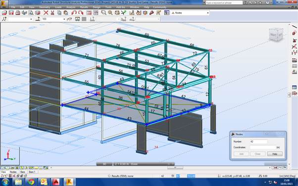
Modelling Cabul Road
The key principles when modelling with Robot are therefore to:
- simplify your structure as far as possible
- only model what you need
- verify and mesh the structure as you go
- know what results you need and what they should look like
- save regularly
Progress on the Cabul Road redevelopment project is ongoing, but somewhat slow. Planning permission is still outstanding and it is likely now that changes to the massing of some units will be required. I have completed a prelim structural scheme, outline demolition drawings, temporary works design to retain a terraced gable wall that will be exposed with the demolition of 4 properties. I’ve also designed the two new large roof structures in structural steel. The project also requires significant underpinning to the existing structure and party walls. I have had to research and learn about the Party Wall Act and what the responsibilities of the developer are. I also understand about Demolition Notices and the Planning Procedure. Other interesting points on this project has been to determine the disproportionate collapse class (the fifth floor of the flats is less than 50% of the total area), basement waterproofing strategy, positioning of movement joints and structural floor choice.

21 Cabul Road
I have also been involved in some other projects. One of these is Albion House, in Woking. It is a disastrously ugly and unsightly 9 floor tower next to the train station. The client’s aspiration is to redevelop the tower and maximise net lettable space, either by removing one of two stairwells, or placing another storey on the roof. The advice that I have been able to provide with MBP is shaping how the clients are costing the alternative business cases. More work is to follow on this one.
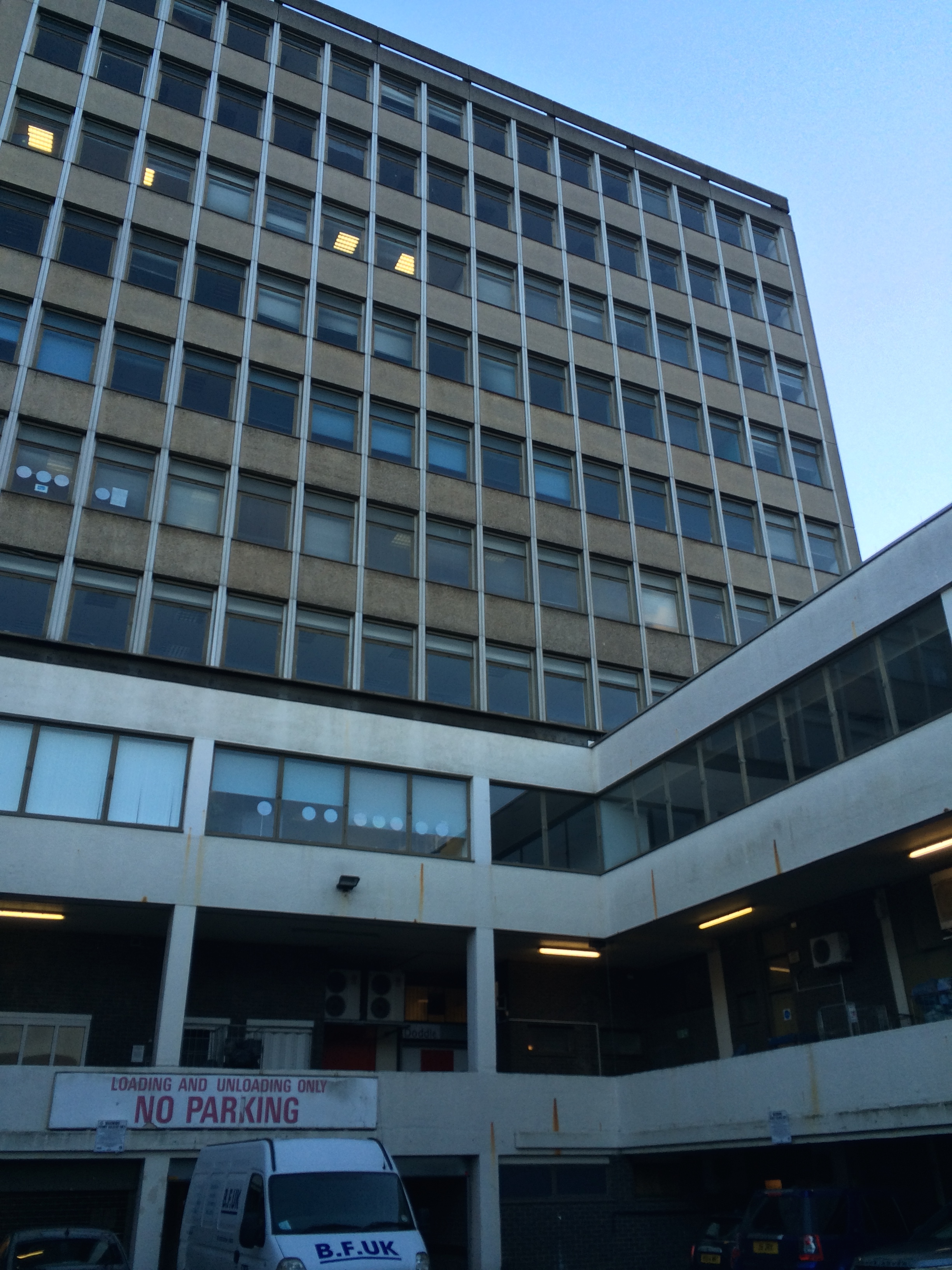
Albion House, Woking
Michael Barclay Partnership support UCL and I’ve become involved in a mentoring scheme. As part of this I am mentoring a 4th year Masters student who is undertaking their design project. It has so far been an interesting and enlightening experience into mentoring.
In other news, I managed to pour a whole mug of hot tea into my lap whilst in a client meeting last Monday. I then had to spend the next 15 minutes drying my trousers under a hand dryer in the loos! And to cap it off when I ran home on Thursday I tripped and impaled my right hand on some spiked railings! I then spent three hours in A&E and the whole of Friday getting surgery. I’m now sat at home with my hand stitched and bandaged like a boxer!

Here are the railings.
The question is, why are there spikes on a guardrail at hand level? It is all rather inexplicable to me! To frustrate me more, having paid PAX personal injury insurance for years since my wound wasn’t from a knife, blast or bullet I don’t get bugger all from them!!! Thanks.

I hope your week was better than mine!
It’s a hole new world out there.
Site Two Fifty One
The aim of this blog is twofold. One – highlight what I am doing and learning on site, and two, discuss unforeseen ground conditions.
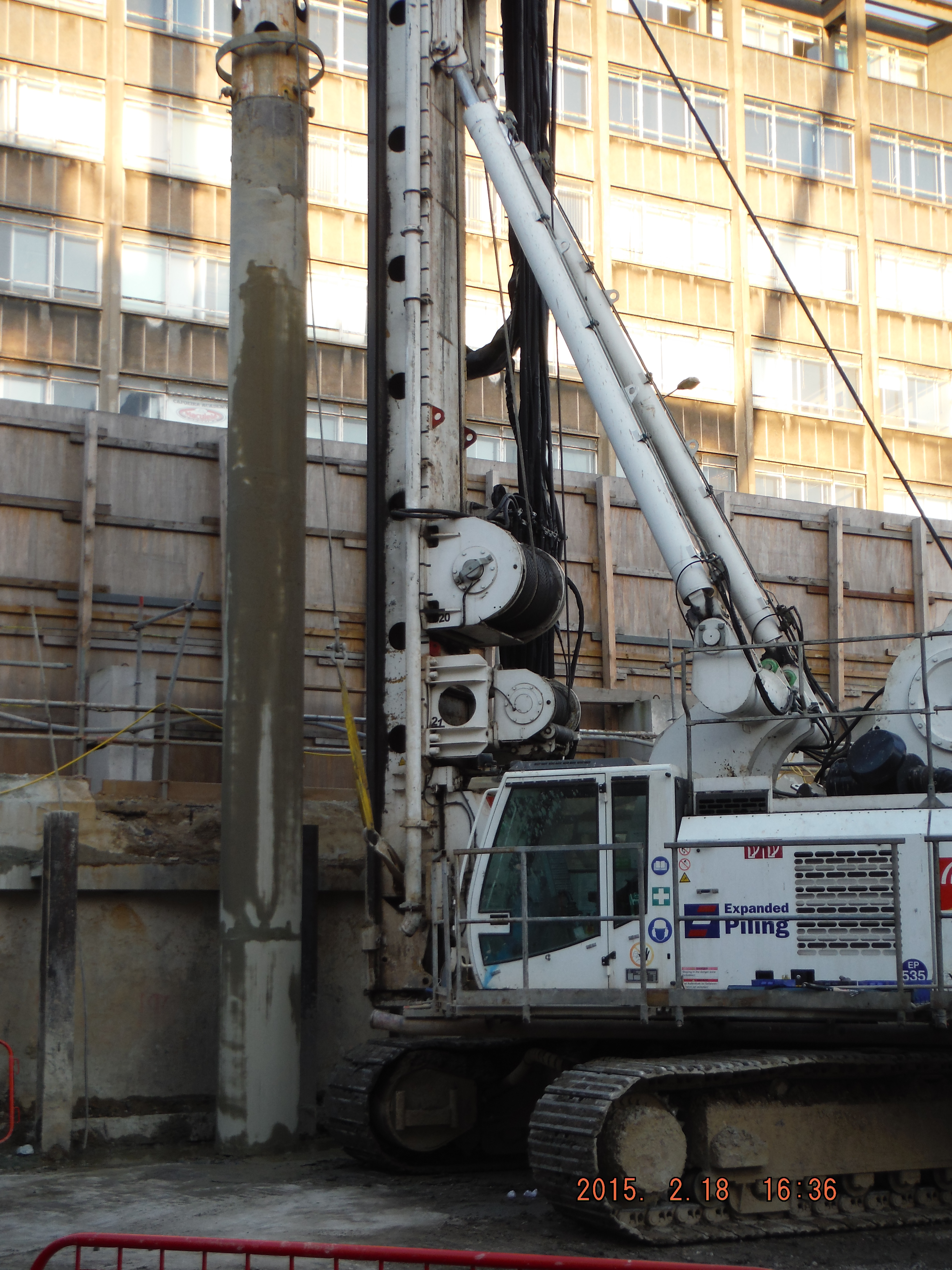
I arrived on site on 16 Feb and since then the focus has been on constructing the secant pile wall. The pre-existing site had one level of basement with an 800mm slab acting as the bottom prop. The slab is being used as the edge of the guidewall for the secant pile wall construction. The male piles, installed at the first basement level, extend to 26m depth through 6m of river terrace deposits and then into London Clay acting as an impervious cut off. The secant wall will act as a cantilever retaining wall when excavation to basement level 2 commences.
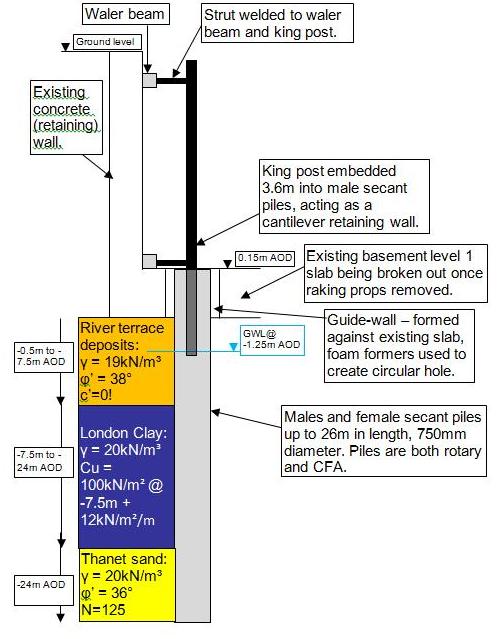
Cross section of secant pile wall, king post propped cantilever and ground model
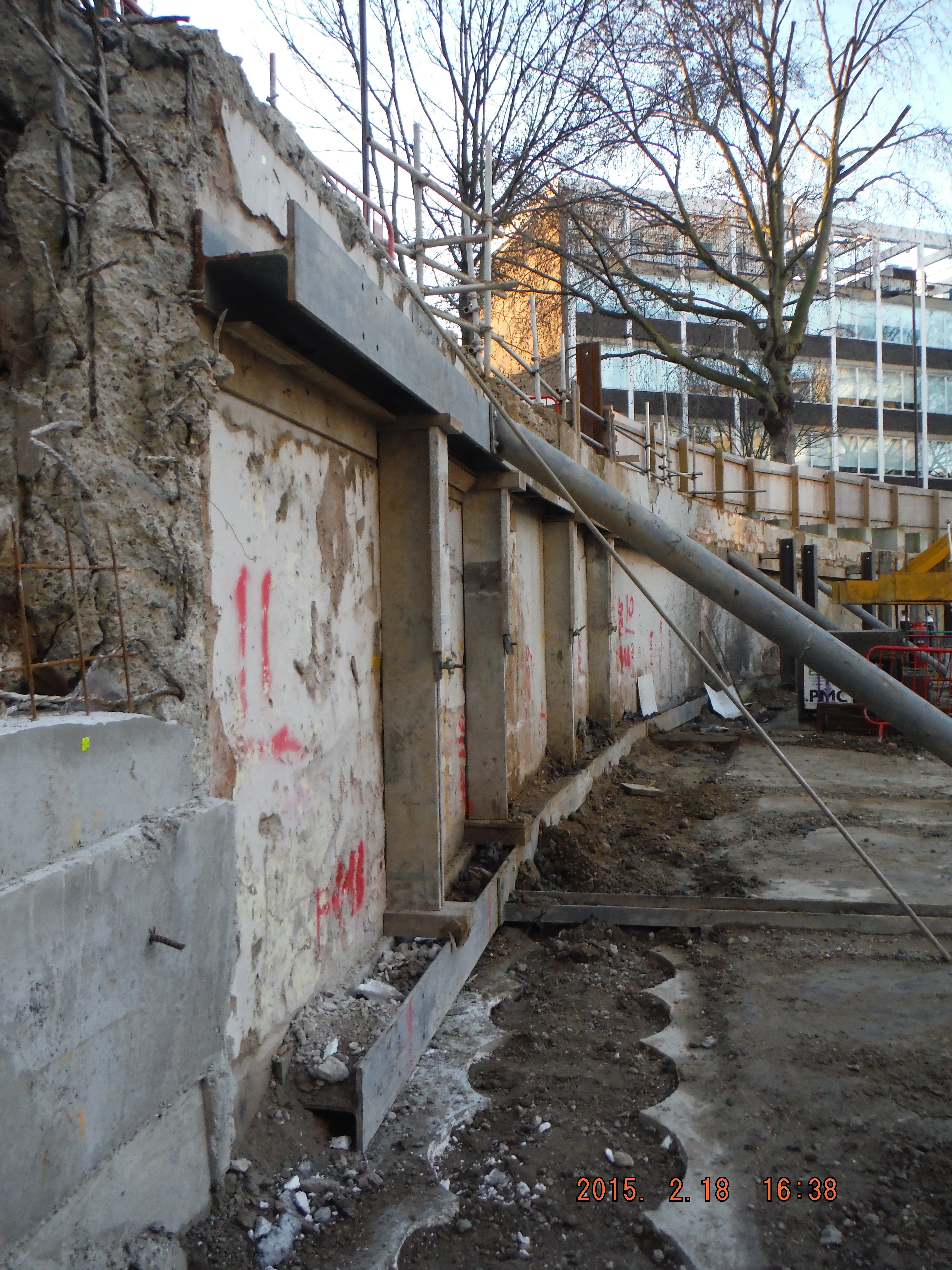
1. Pile Guide Wall (near ground) 2. Raking props to existing slab provide lateral restraint to existing wall (middle ground) 3. King Posts protruding from males secant piles to support existing wall (far ground)
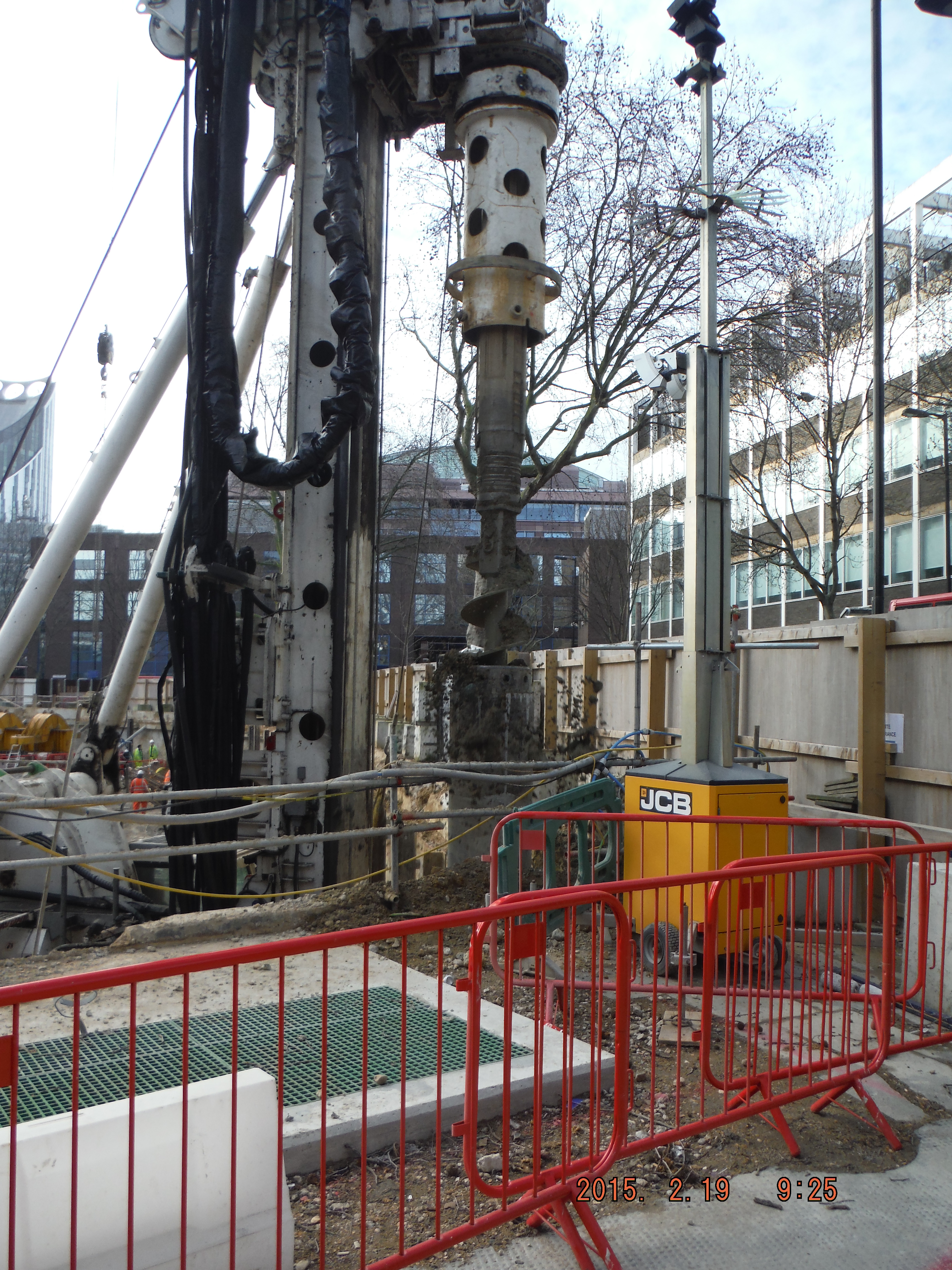
Piling. My role has being to coordinate the piling team to install the piles, specifically where to put king post columns to prop the existing wall up. This just requires thinking about which male and females piles to do to avoid doing them too close to each other and keep the pile rig put of the way of temporary props. Easy in open straight sections, a massive pain in the corners of the site.
Site management. The project is at an early stage so welfare and office facilities are limited. The perimeter hoarding needs to be moved outwards and the live substation needs to be decommissioned after we have set-up a temporary one. Dealing with UK Power Networks and Skanska has been a challenge and I am now very aware of how to excavate around live services (Skanska operatives, however, seem less keen on digging by hand when within 500mm of services…)
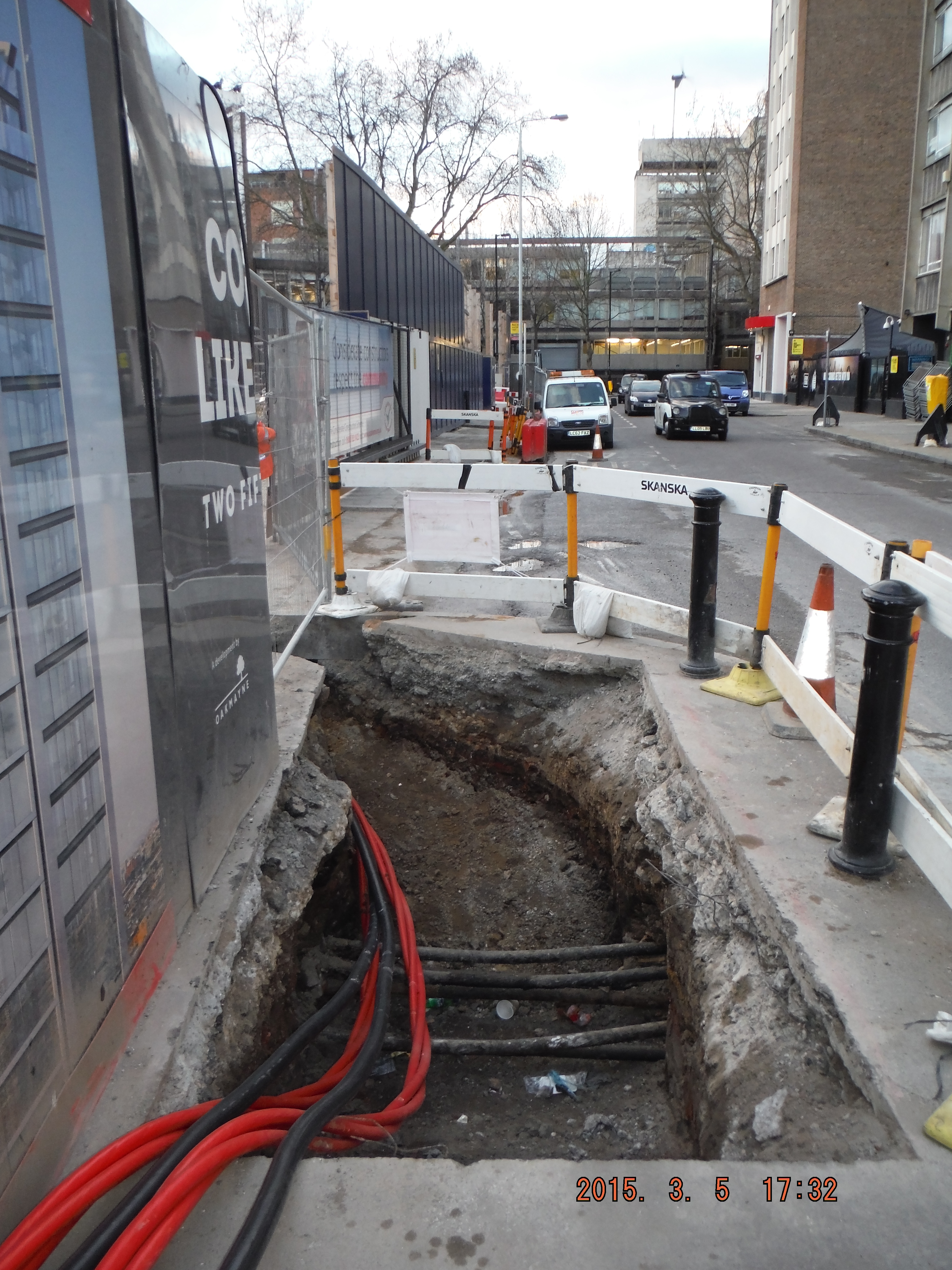
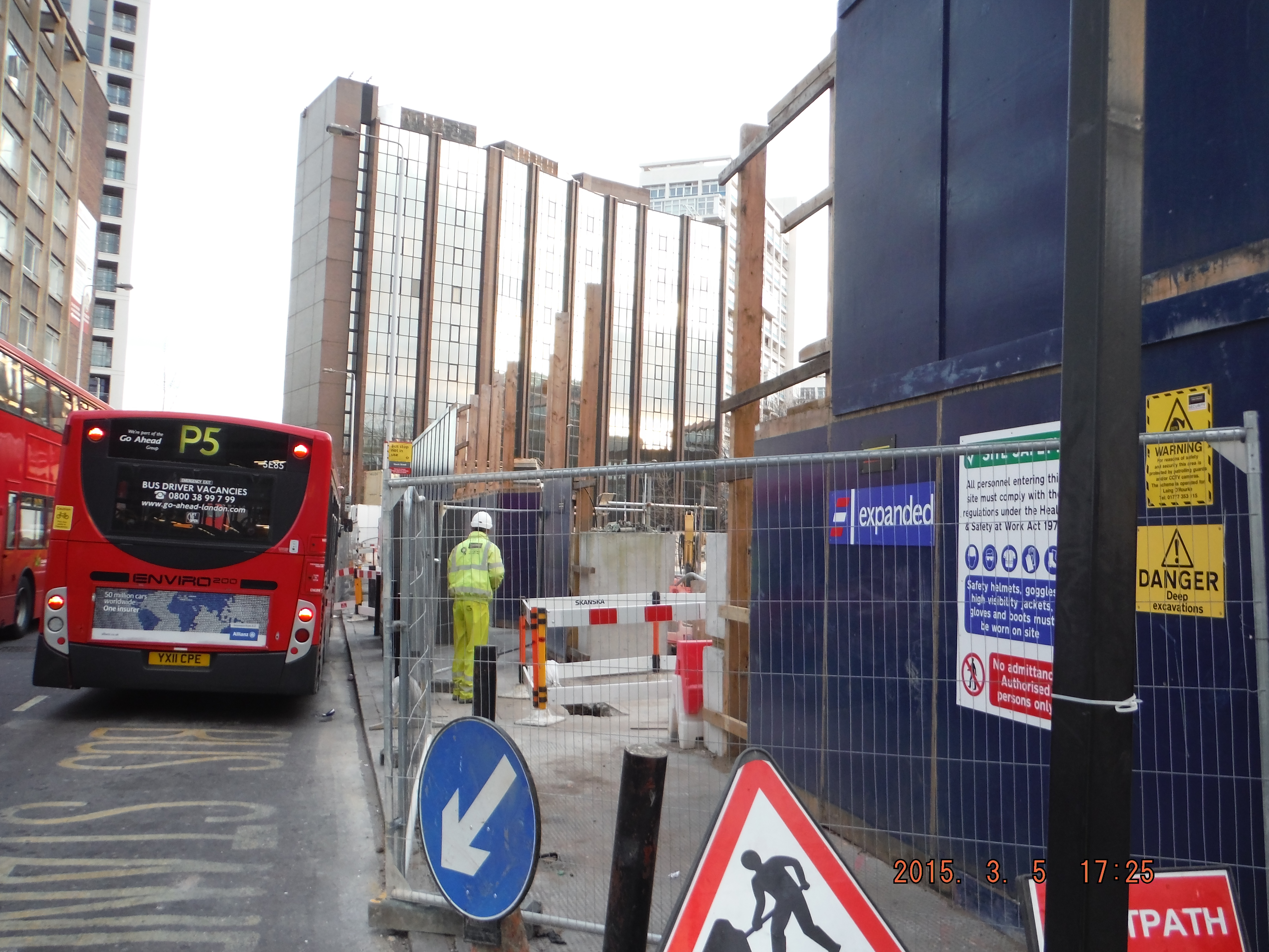
The hoarding move is progressing, but add in moving kentledge blocks close to a 3m deep excavation and a busy bus lane/rat run/cycle super highway there is room for error. Mitigation has been practical though – specific site safety briefings, inductions, lifting plans, segregation fencing and common sense, resulting in steady progress.

Right – hoarding moved within 300mm of blue cycle superhighway Left – heras fencing located where hoarding will be moved to. Note kentledge blocks and proximity to edge of excavation (H&S issues for slinger)
This week I have delivered my first tool box talk – pile mattress construction. Some good revision into the Design Manual for Roads and Bridges (DMRB) (thanks Richard), roller weight, type and width and I am about there. I have learned it is cheaper to order 6F2 (thanks for details of what it can contain Guz/Richard) on a “back load” as we are removing spoil daily. £120 compared to £160, thus making the project manager happy. I am also learning construction terminology: A skip “exchanged” means a fresh one replaces a full one and a skip “collected” is a skip taken away. Apparently “takeaway the full one and bring an empty one” is all too confusing!
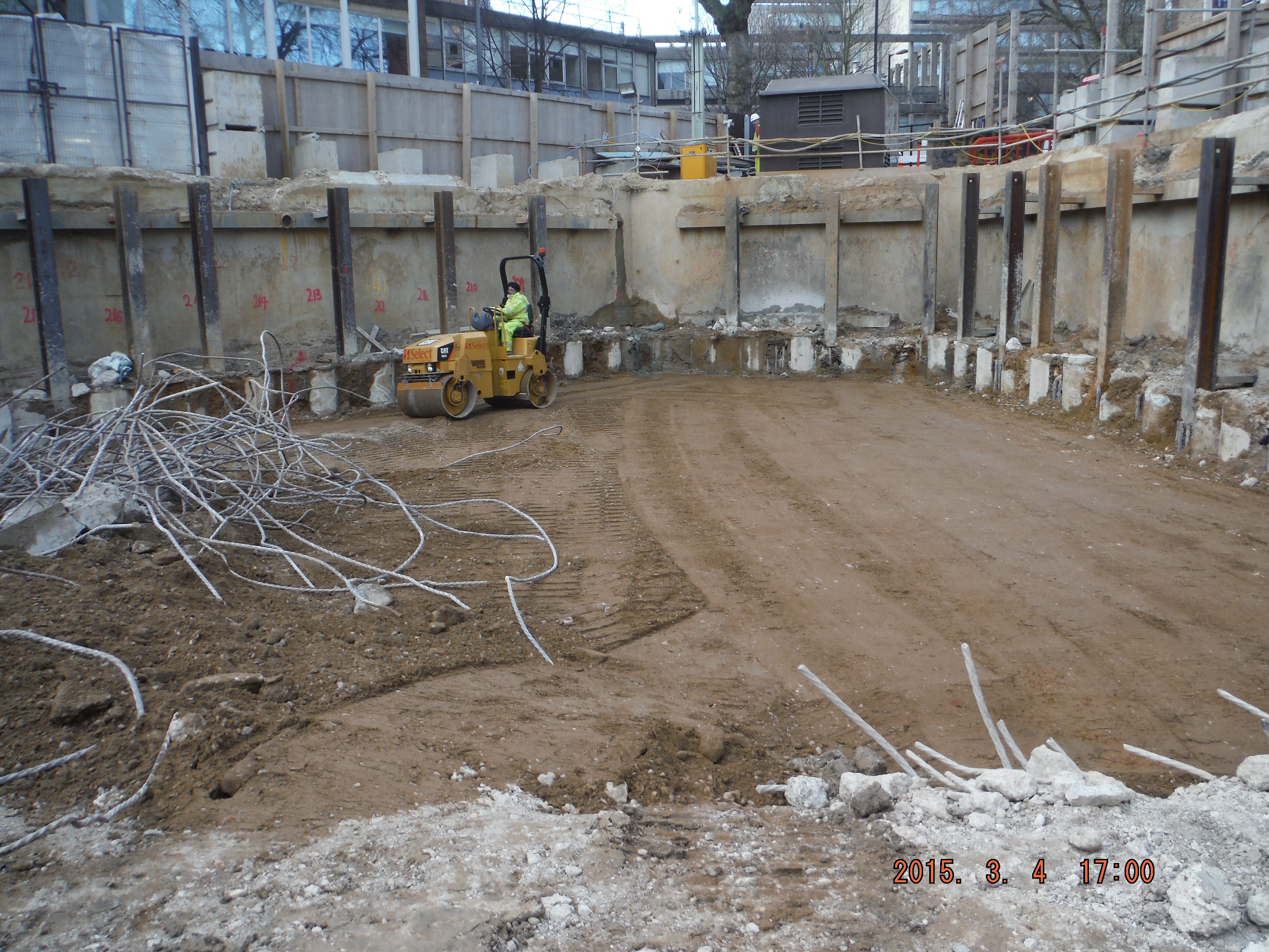
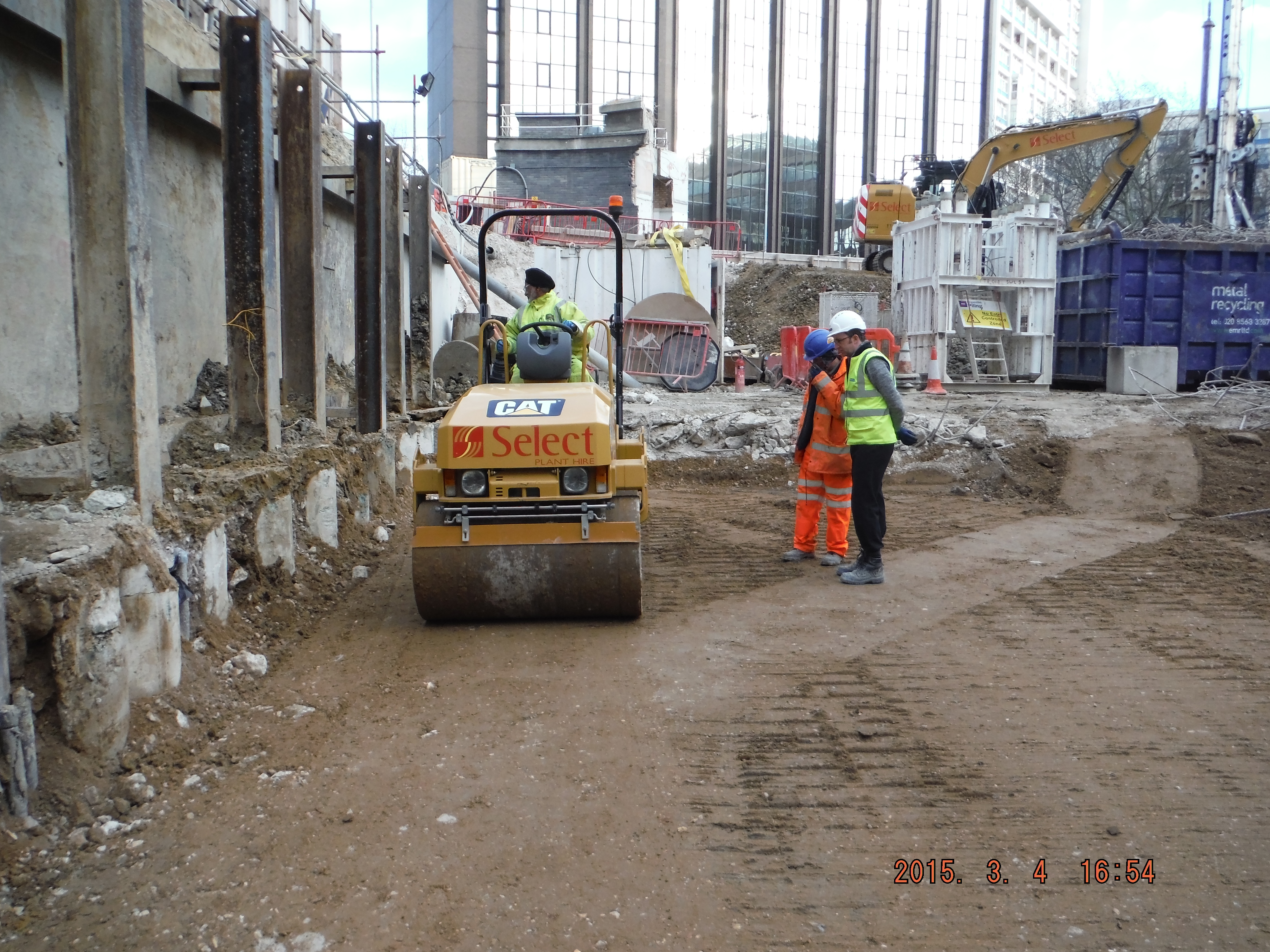
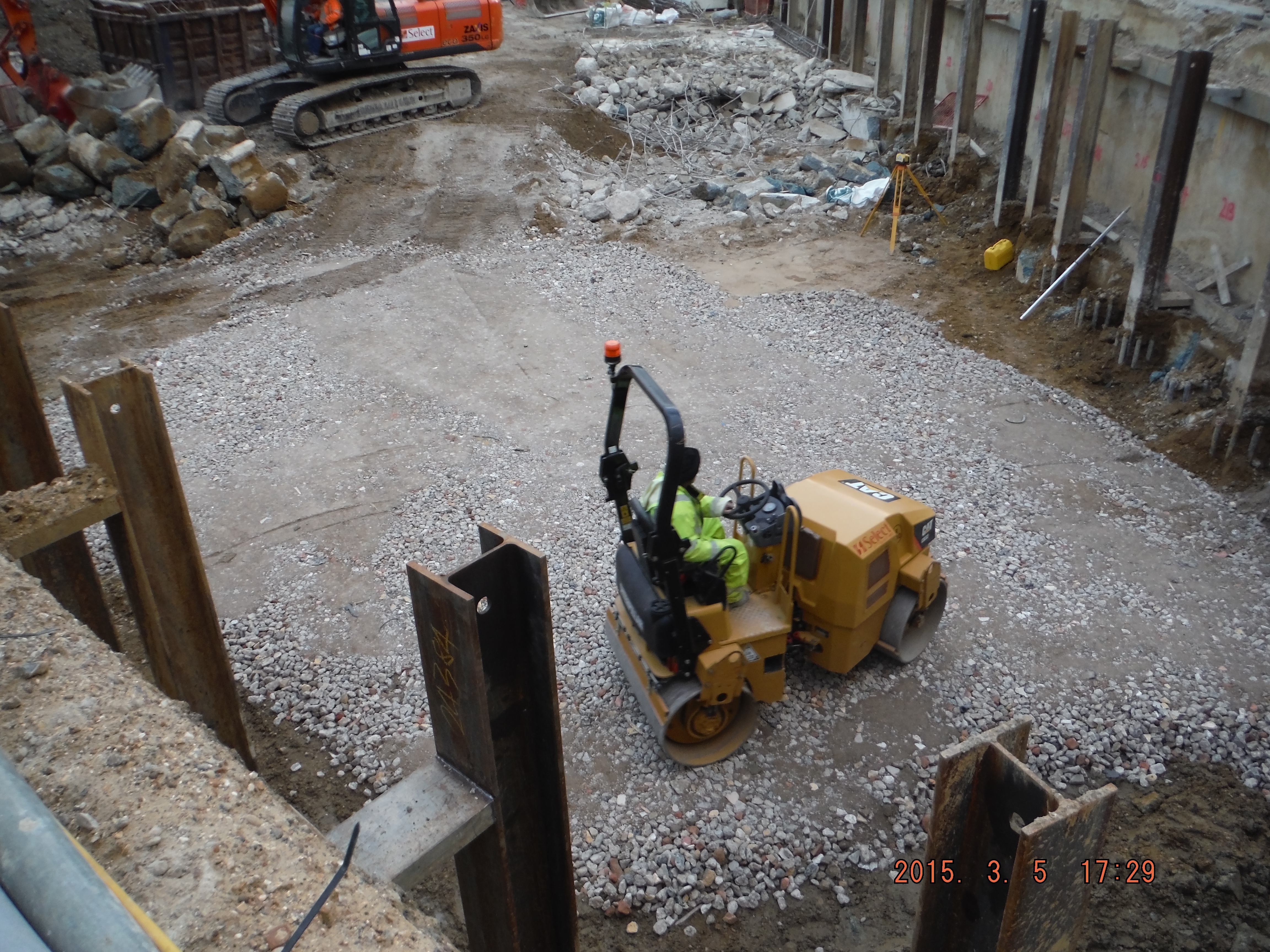
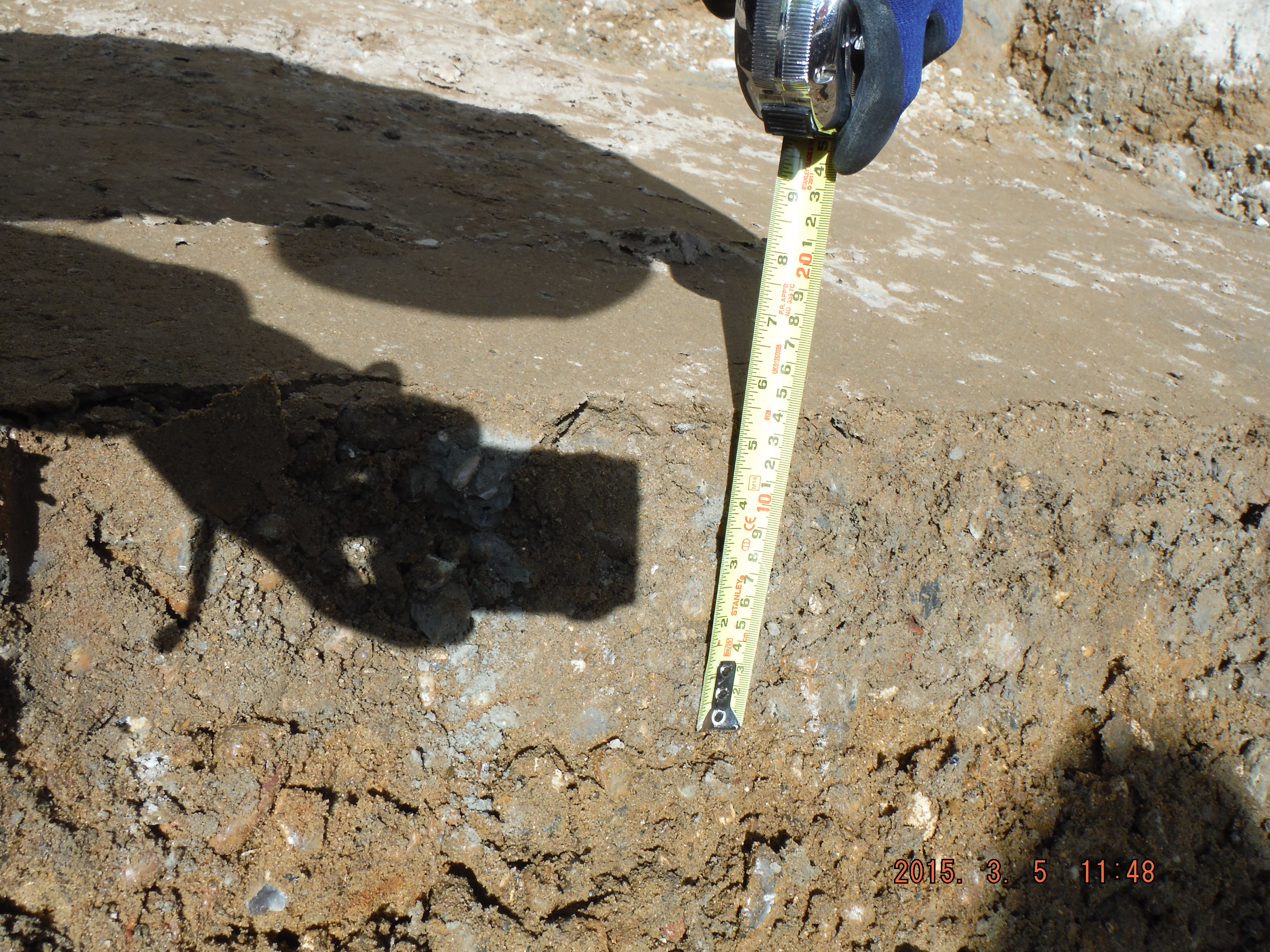
This photo shows compacted river terrace deposits. Rolled with vibratory roller – note depth of compaction – exactly 150mm @ 5 passes – as per the DMRB, now for the 6F2…
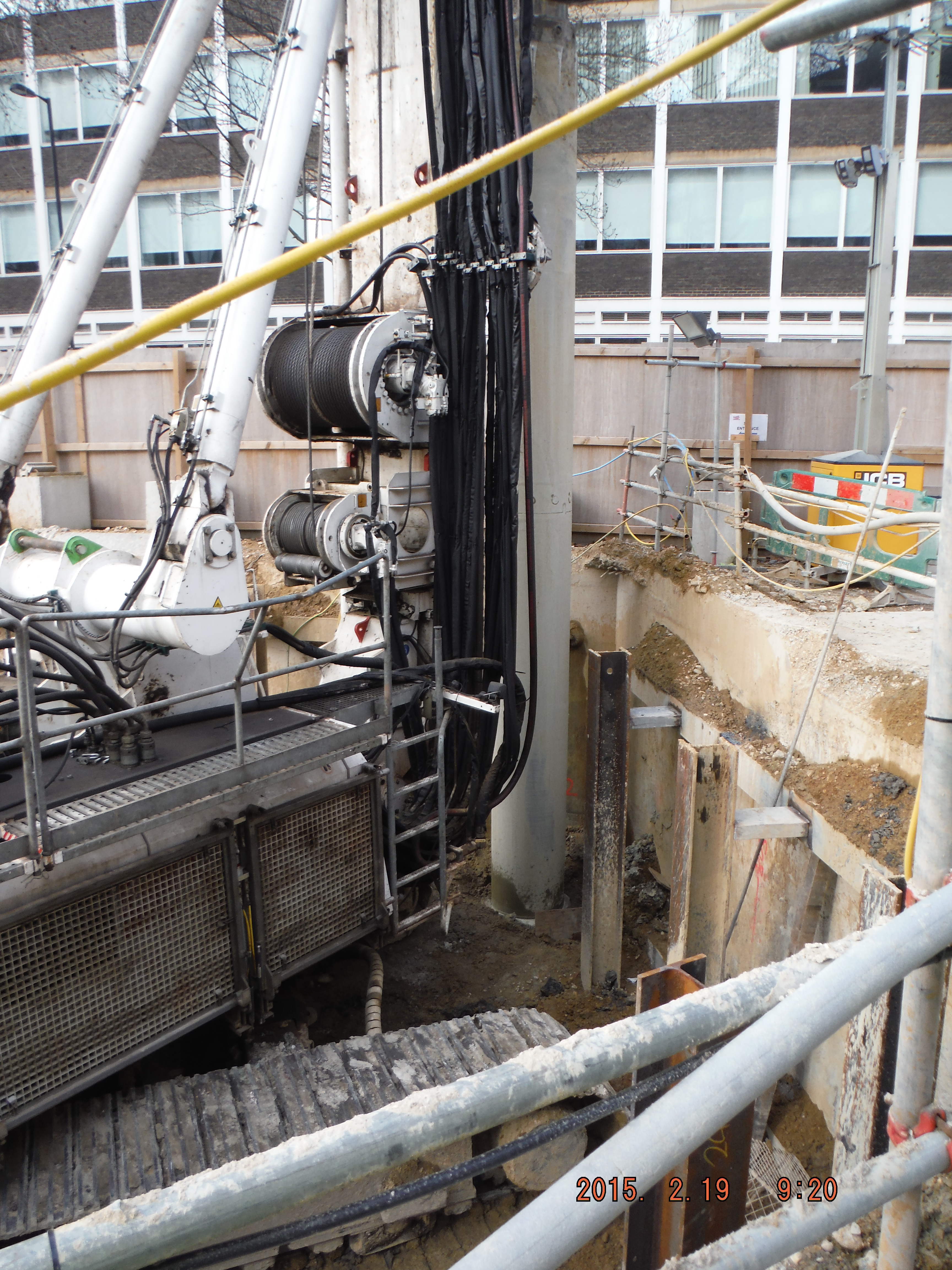
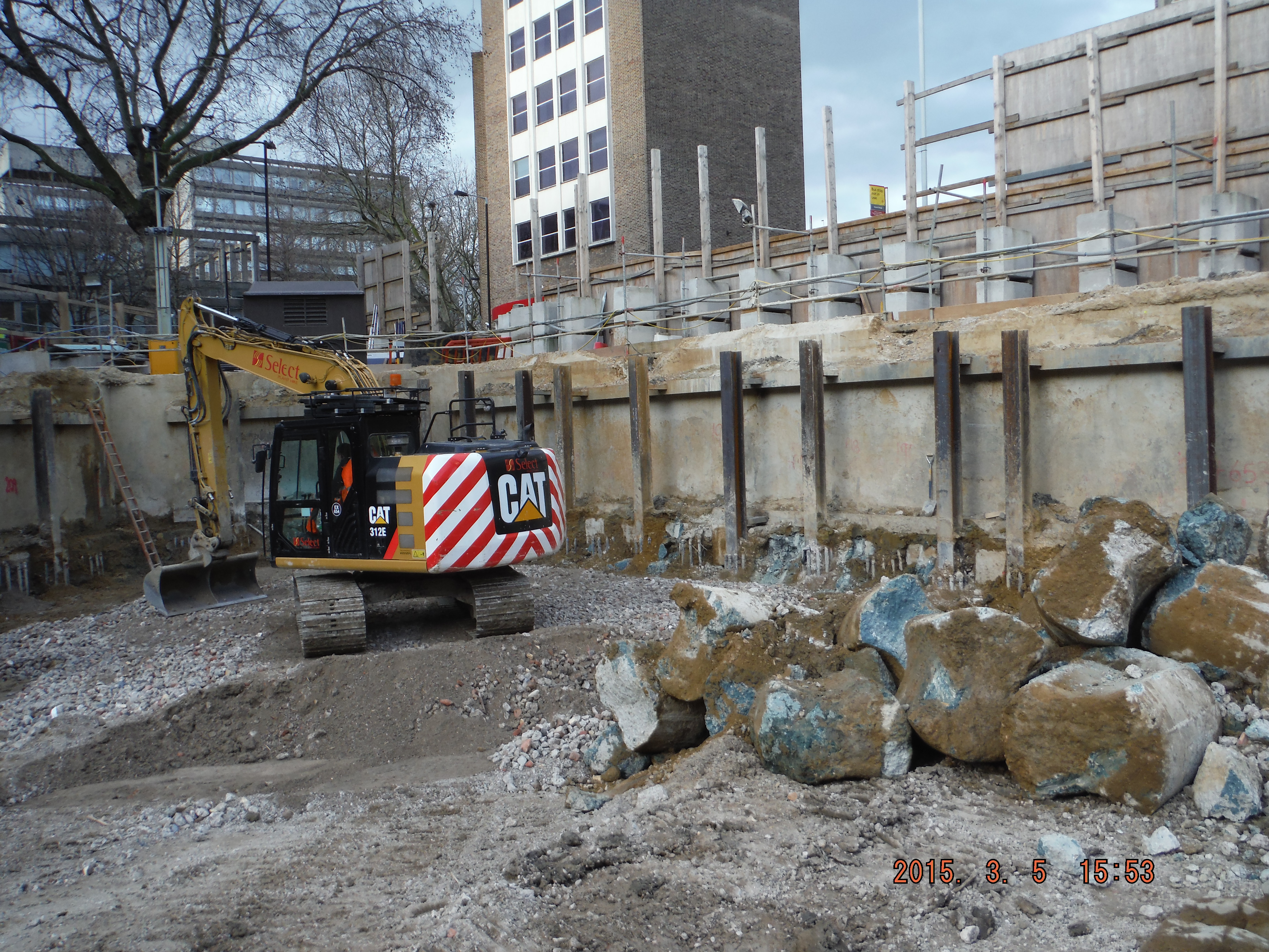
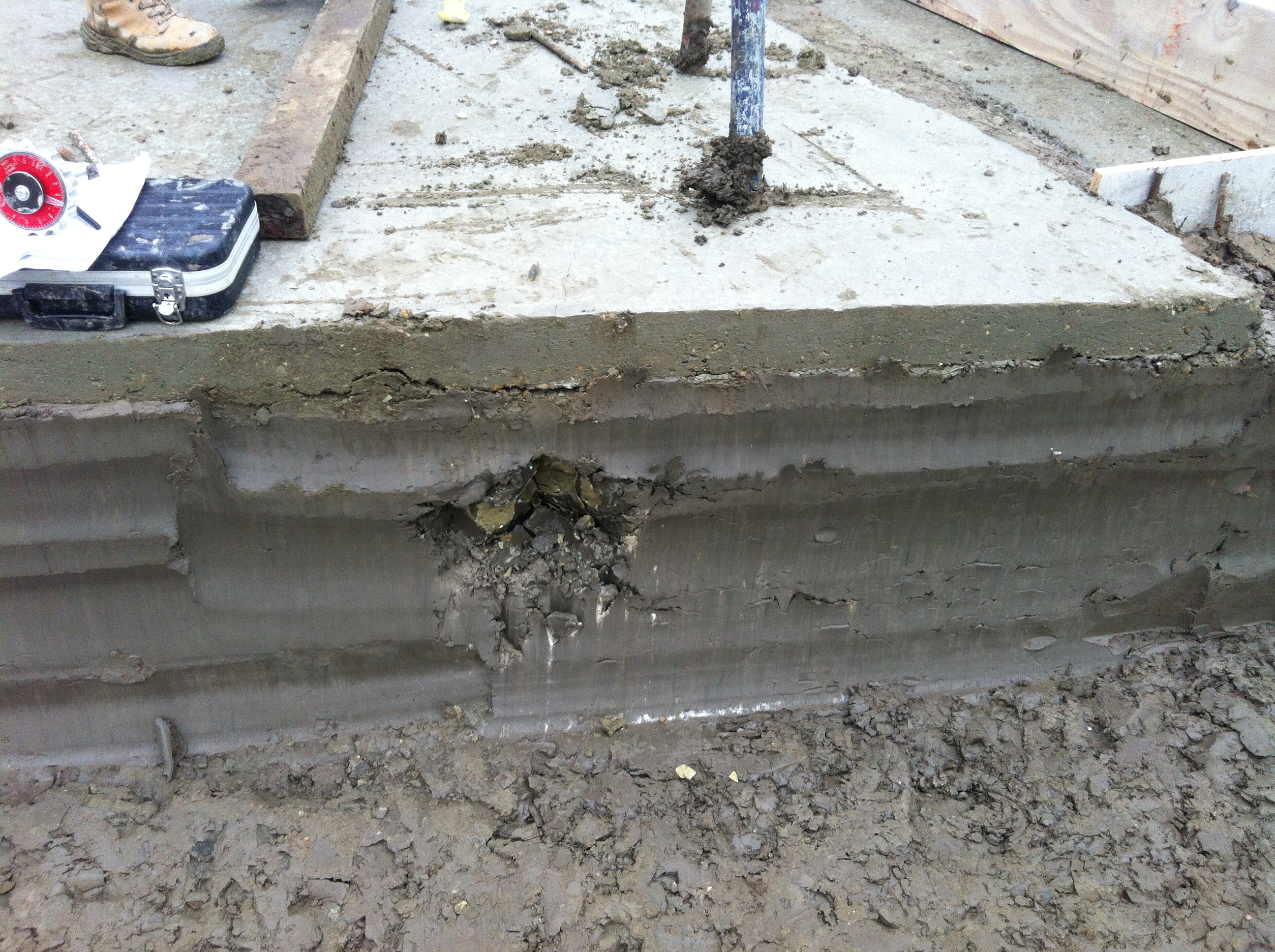
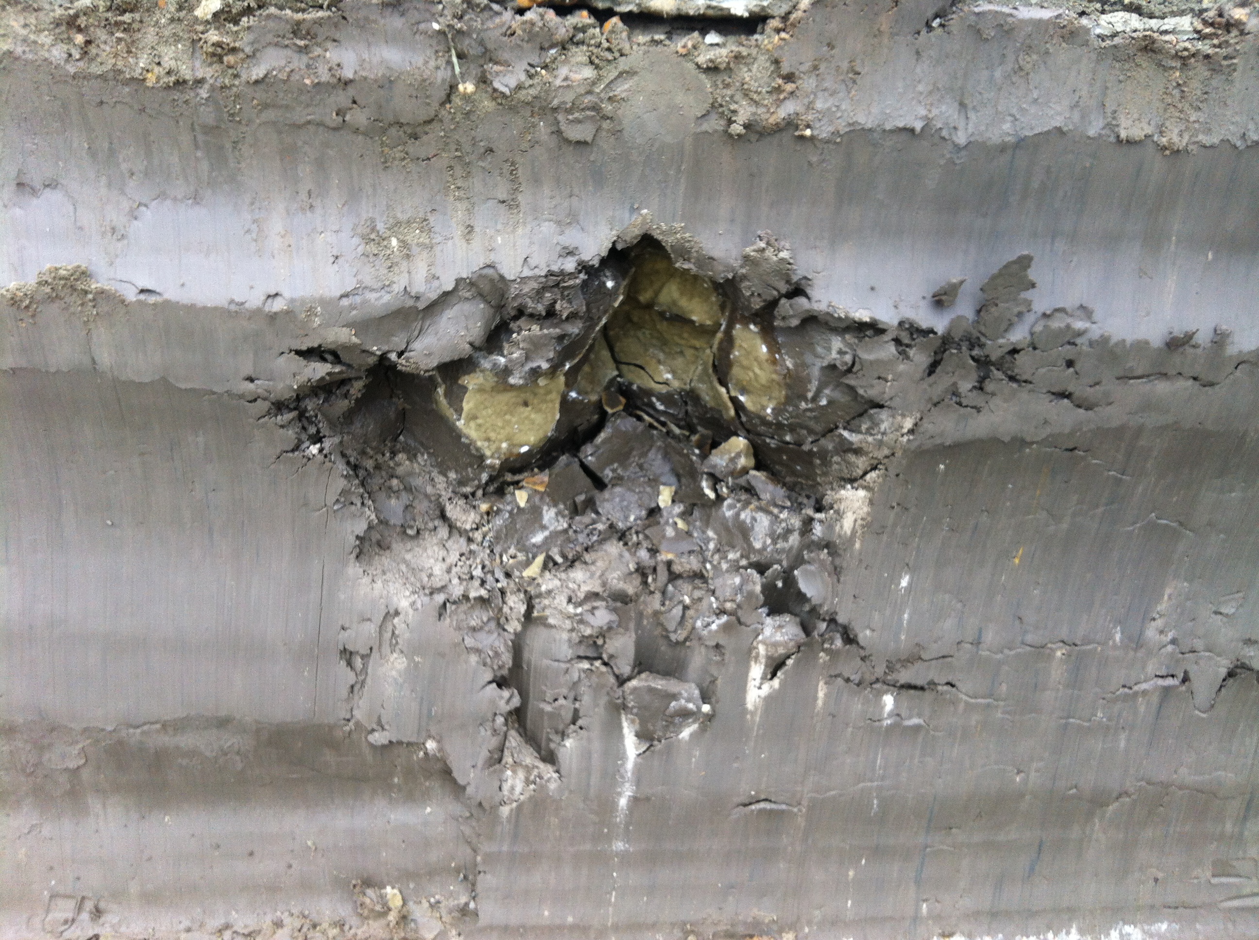
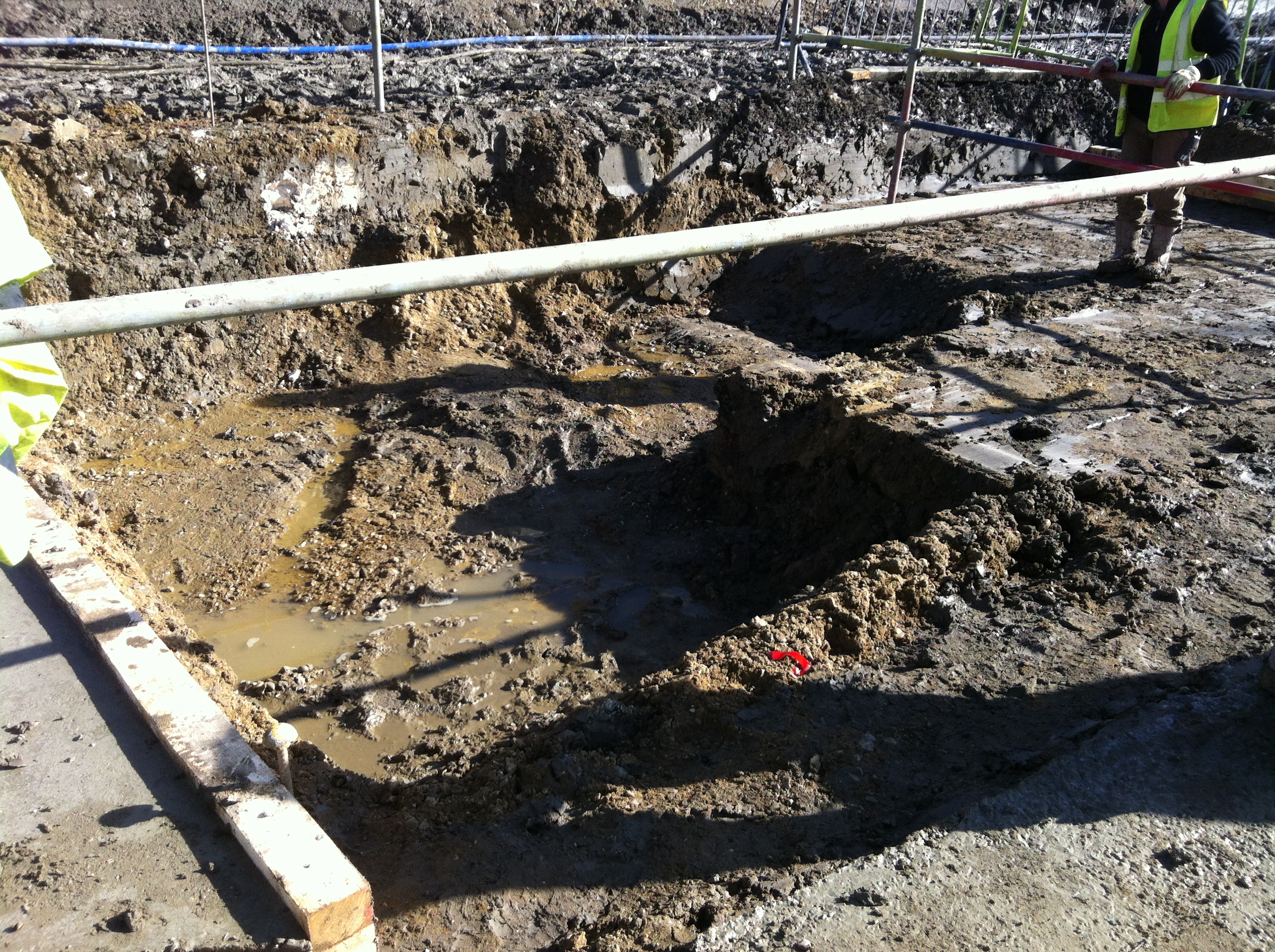
Now for the second part of the pun. After removing the pre-existing slab and some female pile heads it appears I have a floating wall. Well a wall being held up by lateral earth pressure resisted by the king posts and secant pile wall. The hole is about 300mm thick and 1.2 to 2m deep into the underside of the wall.
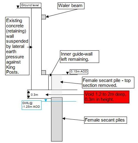
Cross section of existing wall and void identified above female pile which extends up to 2m underneath the wall.
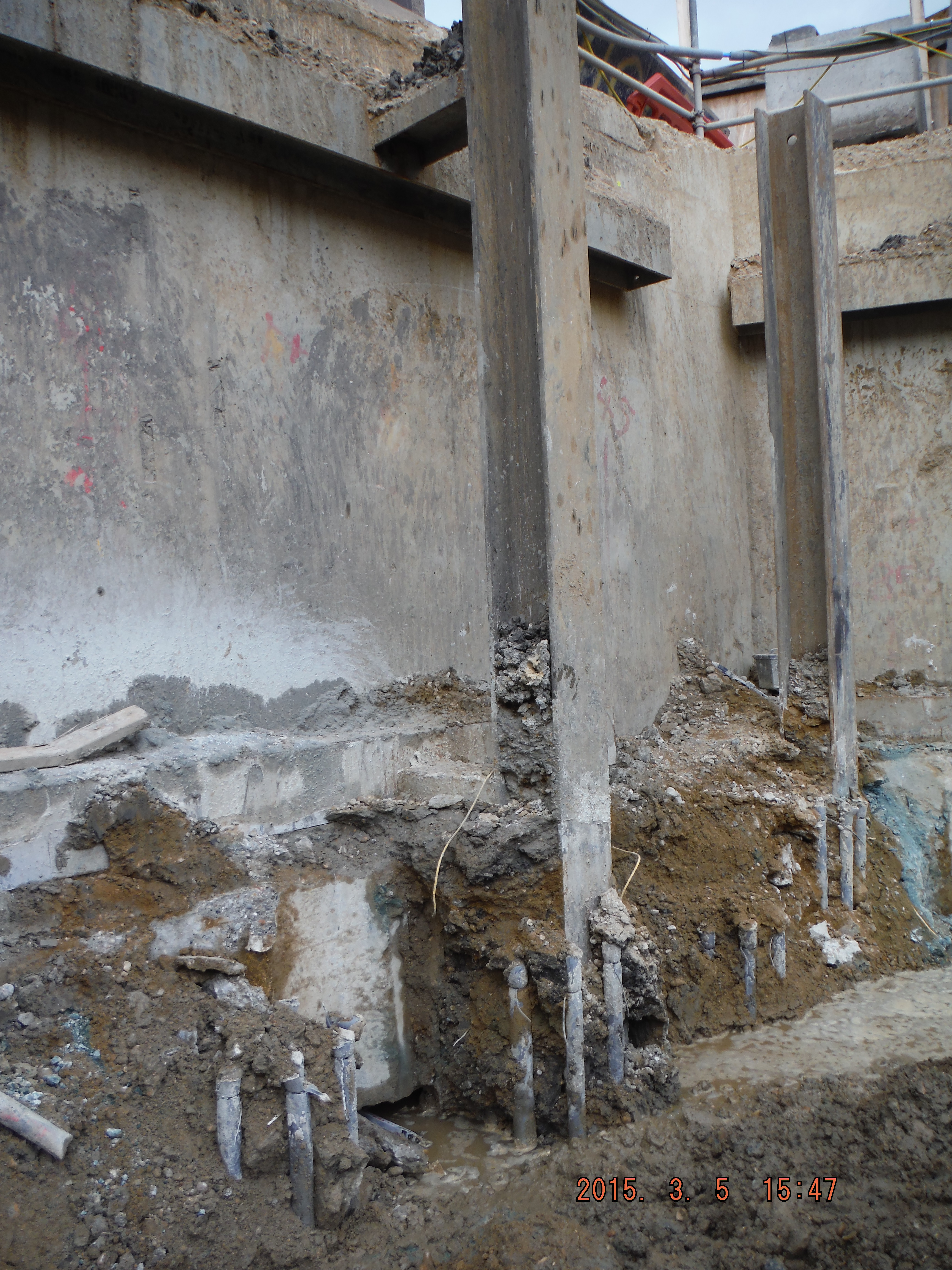
King post protruding from male pile. See void hole to left of king post, between the 2 sets of pile cage reinforcement.
Eventually I had planned to underpin the wall against loose debris in order to construct the capping beam. Looks like that won’t be a problem anymore. Looking into the hole it looks to have been there some time – perhaps the void formed due to water running next to the old slab washing the sand/gravel away (not sure where it has gone to though).
So what to do about the hole… Letter box fill – simply fill the void with concrete from above to close up the void. In the meantime there is already a weekly survey of the wall (mainly to check for deflection into the site, not subsidence of the wall) which has shown almost no movement so I am hoping that it remains that way for a few days longer. We only found the hole today so I am yet to resolve the issue, but as a consideration, if filling with concrete is done it’s roughly a volume of 1.4m (average) by 0.3m thick and extends along about 50m of perimeter so 21m³. Assume £100 per m³ and we are talking over £2000 at this stage and the void may well continue further around the site. Not huge but who pays, client, subcontractor or main contractor…

Progressive Collapse, and other observations….
Last week I was lucky enough to be sidled onto a 2-day course on Progressive Collapse Mitigation run for USACE structural engineers, organised by American Society of Civil Engineers and delivered by a Californian structural engineer – Jesse Karns. The US defence has spent extensive amounts of money in R&D on this topic, and has encompassed its findings and design approaches for all federal buildings in 2009’s UFC 4-023-03 (Jesse was a major contributor in all these areas). Whilst the UFC is not code, it is a guideline requirement for all US federal construction greater than or equal to three ‘occupied’ storeys.
The US approach had admittedly been shaped by British Standards, so much so that the 2005 version of the UFC was almost a verbatim copy of the BS. However, since then, the US government has invested a lot more money into R&D in this area…admittedly due to force protection risk assessments, combined with increased R&D into seismic issues. I was tickled by a comment in the essay distributed by our very own Atkins secondee: “The UK is currently seen as the centre of engineering excellence around the globe”…really?. Well, after this course and a limited time in the US, I beg to differ. The quote needs some justification, for example – the UK certainly cannot profess to be a centre of excellence on levee design and flood mitigation when Holland sits under sea level with its livelihood relying on flood defences, and the US has over 100,000 miles of levees. Nor can it profess to be on a world stage with regards to seismic design when there is limited risk to design for. Off the back of this, I though I’d briefly blog on the US’s present approach to progressive collapse – where they clearly believe they are the centre of excellence, or is this just engineering arrogance…a bit like why it took 1995’s Oklahoma City bombing and the 2001 World Trade Centre Collapse for the US to really rethink the how rigorous its codes were, despite UK’s lessons from the Fallon Point disaster back in 1968. I digress…
The 2009 version is viewed as a pioneering document that leaves BS and Eurocodes wallowing in design assumptions that are based on weak and outdated research (albeit much of the design methodology has the same basis). I though I’d note the following comments that were in the handout alongside the odd wry smile in my direction …’the mechanics of the methodology are much better defined than British Standards’, ‘the past UFC was based on British Standards and were not too bad for RC (some flaws nonetheless), and really bad for steel’.
So, here’s the lowdown, with some initial figures showing the R&D testing set-up for column removal:
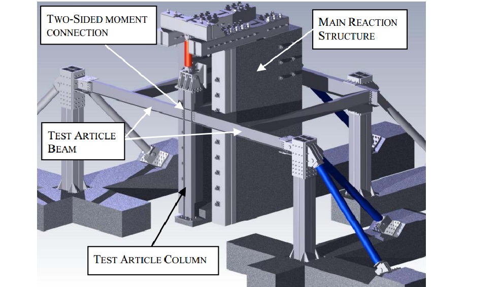
Test model setup for column removal as a result of blast action
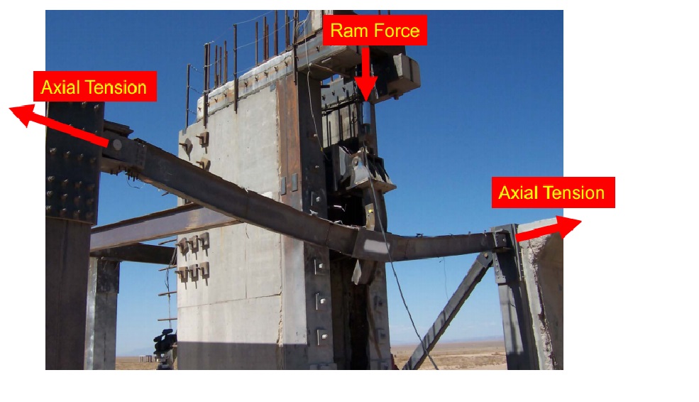
Actual testing post blast (note splayed column)
Design Requirement. As said, the UFC applies to buildings with three of more ‘occupied’ storeys. The design requirements are dictated by an occupancy classification, from 1 to 4 which is relative to consequent impact on loss of life. ‘1’ being structures such as storage or agricultural facilities, and ‘4’ being hospitals, emergency shelters, aircraft control towers. Three design requirements exist:
- Enhanced Local Resistance (ELR). In outline, this is where the shear and flexural capacity of perimeter walls and columns are bolstered for additional protection. It is done to increase the capacity of corner and penultimate columns to resist potential increased lateral forces from tie forces (see below), decrease the possibility that two columns will be removed in an initiating event, and forces a ductile flexural response by limiting shear failure.
- Tie Forces. This British philosophy prescribes tensile forces that hold primary members together. Ties are provided at across each floor level: horizontally (internal and peripheral) and vertically (at columns and load-bearing walls). The theory is based on catenary actions, where internal tie forces are related to beam vertical beam displacement, load and original span length.

- Alternate Load Path. Software design that allows for a localised failure but requires that alternate load paths be available to distribute loads to other undamaged parts of the structure.
The occupancy classification dictates which ones to use e.g. Class 1 – no specific design requirement, Class 4 – Tie Forces, ELR for all ground floor columns or walls, Alternate Load path for specified column and load bearing wall removal
A notable eyebrow twitch came in the results of connection testing. Structural engineers on the west coast of the USA will always design beam-column connections, with detailed drawings. Everywhere east of the Rockies, we just stipulate moments, forces and directions and let the fabricator ‘crack-on’. Why the difference? Well, primarily because of the West Coast’s prevalence of seismic events and the knowledge of how buildings collapse…it has been found in structural studies post 1994’s Northridge earthquake that connection failures have consistently been the cause for progressive collapse. The below graph from tests between 2004-07 identifies the displacement of a central connection directly above a column that has been removed.
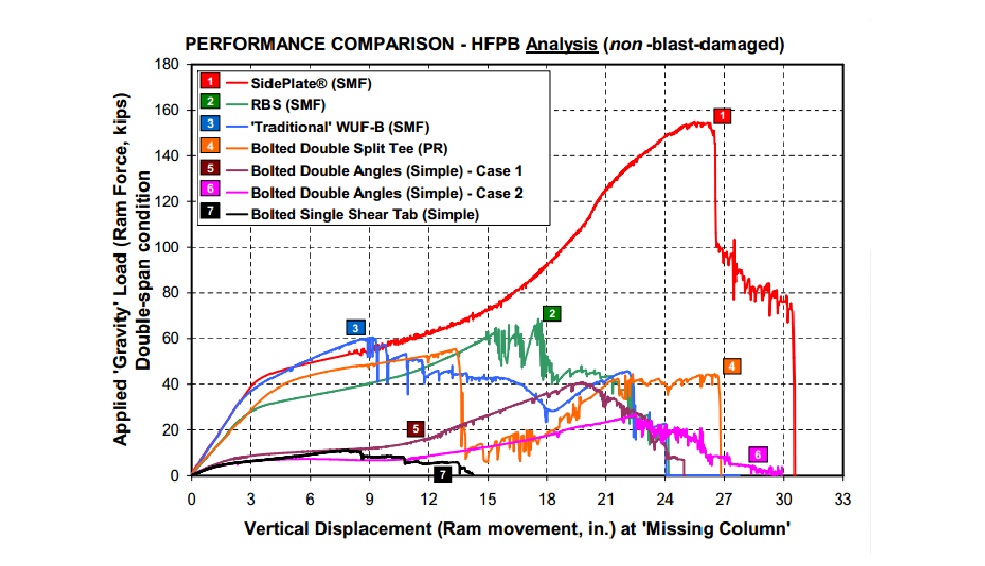
Conscious that we want to harness a beam’s flexural and plastic capacity when considering progressive collapse resistance, allowing it to go into the plastic realm between Fy and Fu (and not beyond), the specific design of connections by an engineer should be essential when considering progressive collapse……
Temporary works for engineers course
Temporary works for engineers course
This week I attended the Laing O’Rourke Temporary Works for Engineers course. I thought I would make some reflections on the course by considering its relevance to the Royal Engineers and the role of engineers on site in solving temporary works challenges. I recently said I would avoid text heavy blogs so I am already breaking my own rule; therefore I have stolen some pictures from Google to break it up!
I have uploaded the pre-course assessment as a general level of expectation of the knowledge of the engineers prior to attendance.
The course was run by the head of the Laing O’Rourke Temporary Works office, Kit Yardley, supported by their senior geotechnical engineer, Keith Miller. The target audience for the course was civil engineering and building graduates who had gained significant site experience (therefore about 5 years since graduation). The aim of the course was “to give participants a working knowledge of temporary works, group procedures, use of the Laing O’Rourke precast assembly manual and the use of current EN/BS standards and guidance in the industry”. The course achieved this aim and effectively covered content within the PET (C) structures, foundations, applied structures modules condensed into only 3 days with a fairly healthy A4 folder to take away.
Course content – PET officers are well prepared technically.

What is the safe depth of an unsupported excavation…
The participants were not required to take in all of the subject matter but become more aware of risks of working with, and designing, temporary elements. The course content included cranes and hoists, soils, excavation support, formwork, falsework, backpropping, concrete pressure, scaffolding, loading platforms, pile/crane mats and many other temporary works structures. I found it comforting that the majority of the theory behind each of the topics was covered on the PET course, where others clearly had not recently been refreshed in modules I cited above. Most of the participants completed the pre-course work getting all of the answers correct, although a couple struggled with question 8.
Experience required.
The area which was unfamiliar to me was the understanding of proprietary systems that are used for falsework and the Laing O’Rourke precast system. While this sort of knowledge can be gained now on site, it is somewhat symptomatic of the imbalance of site experience PET officers have compared to their technical understanding gained on Phase 1. I believe it is better to have a technical understanding which is then enhanced through gaining practical experience on site.
Temporary works course for military engineers.
I would strongly argue that with a little tweaking of specific lectures from the PET course a very thorough and relevant temporary works course could be delivered to military construction forces. The challenge would be to deliver sufficient practical information to the MCF. There were numerous insightful examples of good and bad temporary works practices delivered during the Laing O’Rourke course, supplemented with photographs, sketches and You Tube clips and so I am sure relevance to military engineering projects could easily be achieved.
I think a temporary works coordinator course would be a useful addition to the set of tools delivered to an MCF project delivery team. The ability to recognise the non-designed temporary works that are required for a project to be delivered, and how they are to be managed (identified, designed, checked, certified, monitored, reviewed), would only improve the efficiency and safety of a project.

- Cause of failure? Prop locations, different crane used to that designed for, outrigger spreaders

Conclusion
My initial view of working on a Laing O’Rourke project is that they appear pretty diligent regarding temporary works challenges. Their engineers get site experience after graduating from a civil/building degree. There is a rotation between sites (it seems everyone will do their time at Hinkley) to gain broad experiences. When suitably experienced, engineers are trained (refreshed) in engineering principles to strengthen their ability to manage and lead temporary works. This seems pretty analogous to officers within the Royal Engineers but perhaps a slightly greater emphasis on temporary works for the wider Corps MCFs should be made (as well as the many other courses they are now advised to complete) as we move back into an upstream capacity building role.
Quick, there’s a condition…!
A short one this week as I finish off my first draft of AER1 – wow they come around fast!
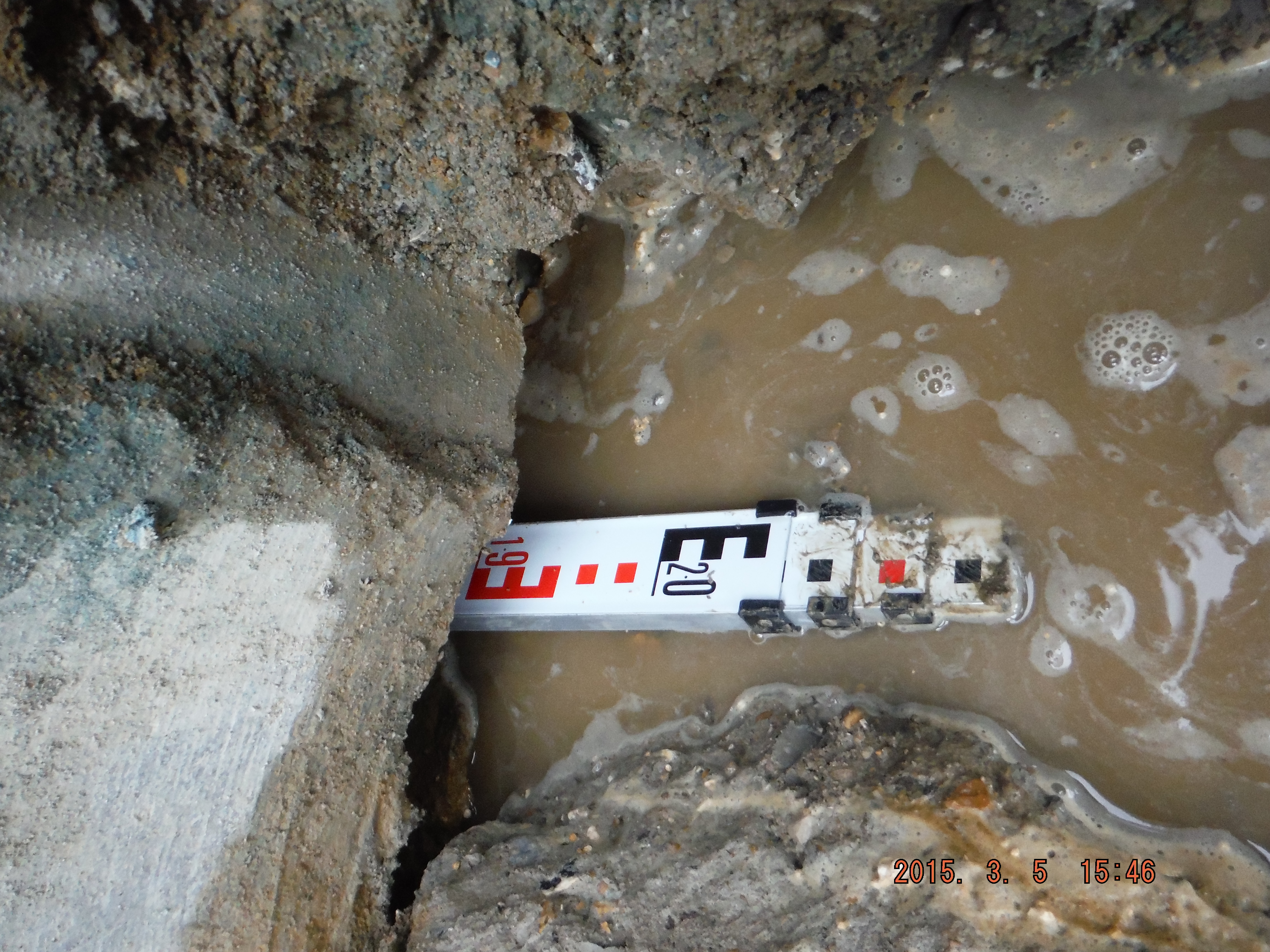
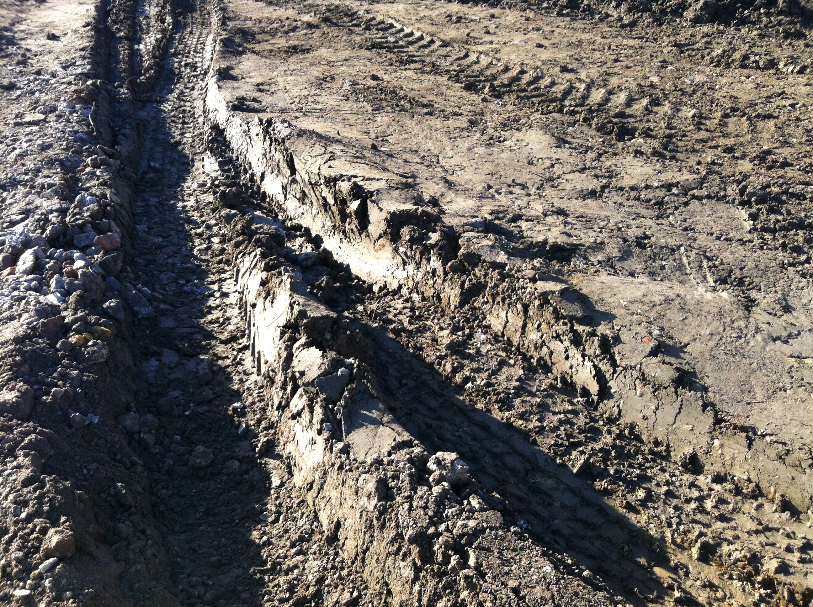
WARNING – GRATUITOUS MUD SHOTS!
The majority of my site is London Clay, unsurprising given it’s location. Damo’s site is similar. I know this as when I met him in the pub last week he brought some to show me! The clay here is so overconsolidated that it has started to form localised soft mudstone deposits. Therefore it is to water what John’s worked examples were to me: impossible to get through!
Area in general
Area in detail
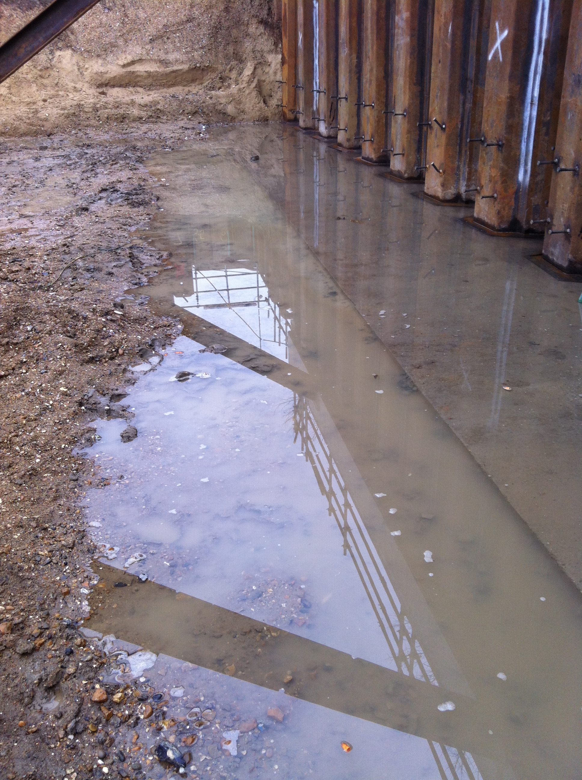
The clay is overlaid by river terrace deposits, a much more permeable material. And since the whole site is one big cofferdam I’m fairly sure I’m getting flash-backs.
The clutches on the sheet piles have been welded down to the puddle flange which will eventually sit at the bottom of the slab. Below this they’re not welded and in the sandy gravel areas this has led to water flowing in under formation level.
The spec states that where there are localised areas of clay in the sandy gravel, that it should be removed and replaced with type 1 or concrete blinding. But it makes no mention of areas of coarse material within the clay. So when an area of sand was found within the clay the sub-contractor kept digging in an attempt to find the bottom. And then stuff started sinking. Most notably a bloke holding a levelling staff.
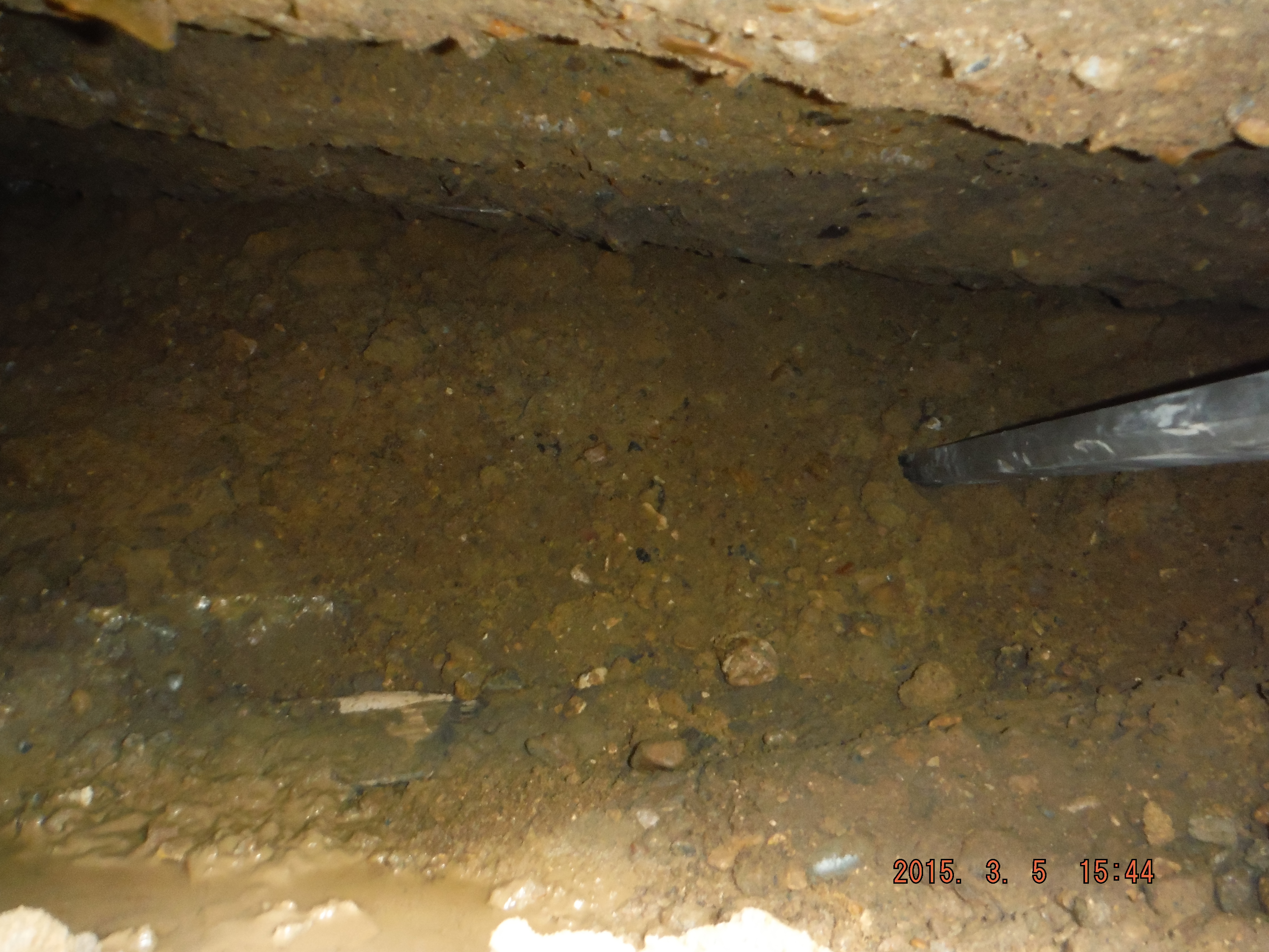
Dig for victory!
They’d made two mistakes. They hadn’t considered why areas of fine material in course need to be removed, but areas of coarse in fine don’t – settlement. And by trying to dig to find solid ground they had created a hydraulic gradient and therefore a quick condition.
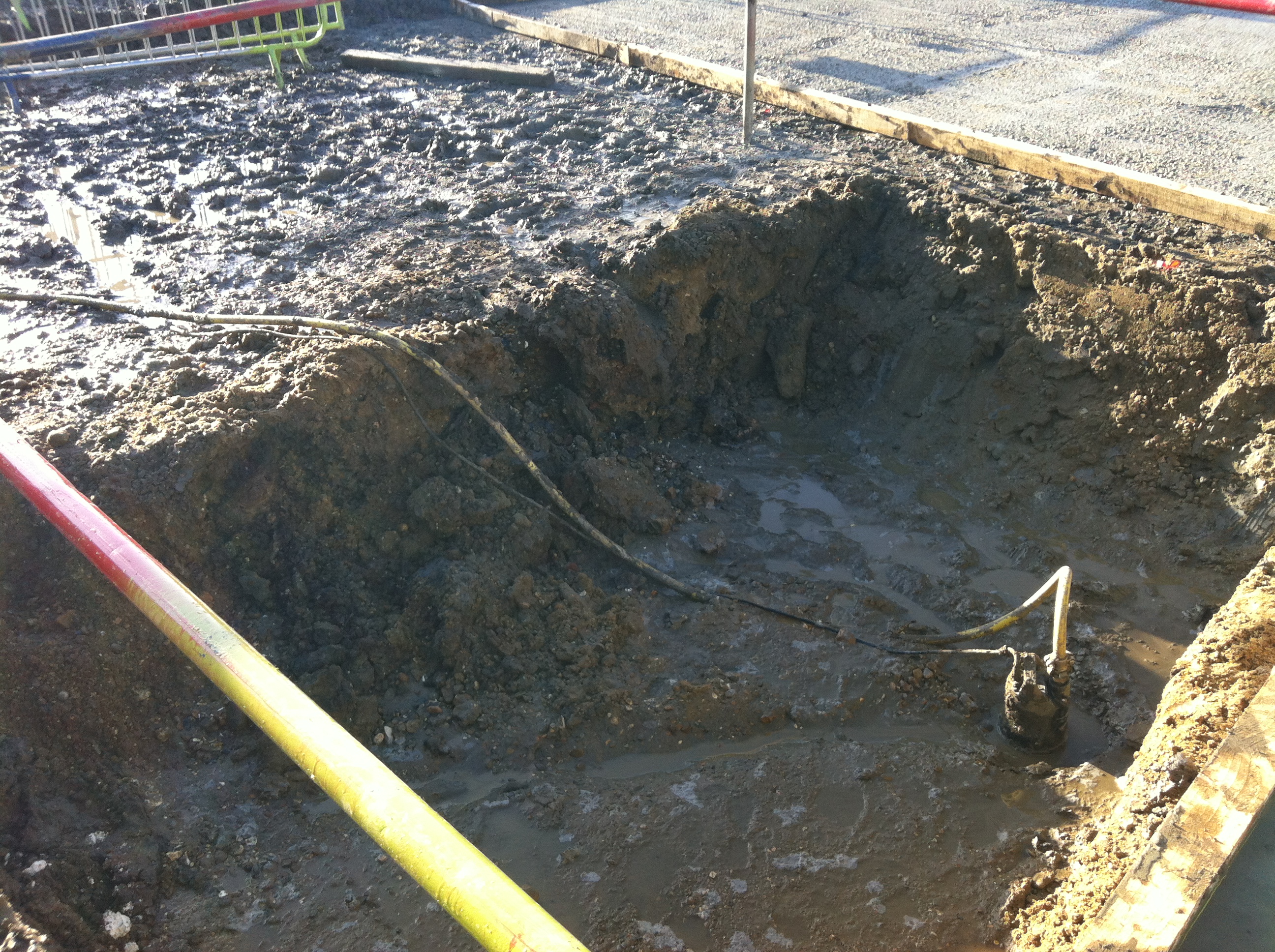
The sandy hole
Once they stopped digging and started pumping the ground solidified. They filled the hole with some concrete that got rejected from a tower crane base pour (another story involving slup tests) and continued on their merry way!
CPR Gold!!
Atkins are very good at providing fodder for Continuous Professional Development. I have a ready supply of wider industry news articles and studies to scan, over my packed lunch, which depressingly I take ‘al desko’.
This struck me as a good CPR handle, as skills shortages are surely one of the main strategic risks to the UK construction industry as it struggles to deliver the National Infrastructure Plan.
Enjoy
Concrete or Steel Roof Sir…..Are you sure?
ith the 30% concept design completed and off for approval I thought I had arrived at the start of the detailed design. Armed with my vast amount of knowledge and more importantly a phone line to the rear guard in Chatham I was ready to dive into some detailed engineering calculations…or so I thought.
Turns out that since January the design has been turned inside out and some fairly significant design issues uncovered that should have been mentioned in the 30% design.
Concourse Slab Strength. The concourse slab has not been design to carry any further load other than those loads present I the permanent state. During the temporary state the concourse will be required to hold the form work for the roof slab. As it turns out it has not been design to hold the additional load of the wet concrete roof slab as it cures. As a result the propping for the roof slab will need to extend through the concourse slab with either large props passing through the concourse slab or a forest of props at both levels. As this is a bottom up build the contractors plan and the project programme is based on the M&E fit out occurring concurrently as each subsequent level is completed. With the proposed forest of props at the platform level the contractor will not be able to complete the M&E fit out until the roof slab has cured. This puts the project programme at significant risk.
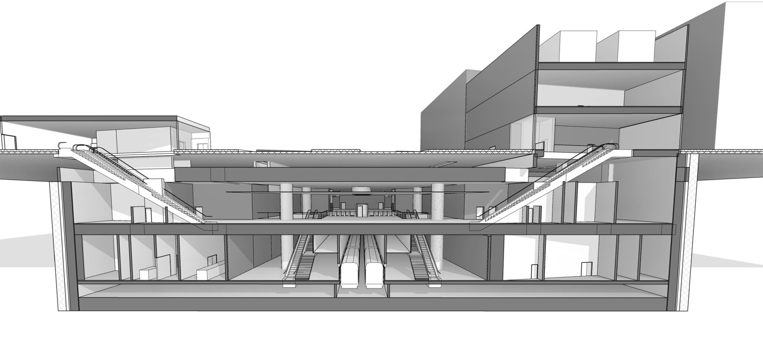
Current sections of architect model. The odd shape accopunts for a Highway fly over foundation,road junction and buried services. Section shows platform, concourse and roof slabs
Steel or Concrete Roof. With the issue of concrete curing times and excessive propping the contractor proposed a change to the design that saw the concrete roof slab replaced by a steel beam and precast concrete roof. This particular issue was passed to myself to see if it could be done. Given that some of the spans are nearly 30m this would require some fairly large beams…turns out about 2m deep plate girder beams with 80-100mm flanges should just about do it. The issues faced when designing the concept for the beams are outlined below:
Supports as the rest of the structure is concrete the tying in of the steel beams to the concrete supports to make full moment connections would be particularly difficult and is likely to result in excessive cracking at the interface of the steel beam and concrete. Cracking as my previous blog is a particularly sensitive issue on this project. Therefore the beams would need to be simply supported.
Simply supported beam results in a high bending moment at the mid-section of the beam as the beam is free to rotate at the support and no moments are passed to the concrete. As a result the beams would need to be deeper than if the beams supports were encastra.
Deflection. Given that the beams would be in some cases spanning nearly 30m the deflection at the midpoint was in some cases up to 100mm. Not a large deflection I’m told but any deflection of the beams would encroach on the architects and M&E services spaces. To counter this I suggested that the beams could be pre cambered i.e cut to account for the deflection so that as they did deflect they would then settle at a level.
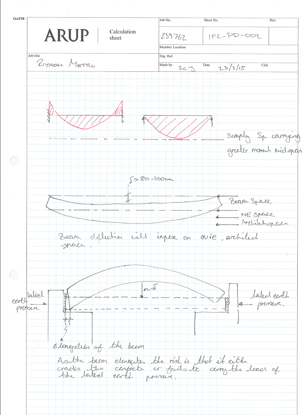
Elongation. With deflection now sorted my attention was turned to the elongation of the beam. As the beam would deflect from a pre-determined camber to a level that beam would also elongate. As the beams were to be simply supported but would also be required to act as props the beams would have to once extend and rest on a bearing to carry the axial load from the ground and support the box. To ensure this actually happened would be very difficult given design and construction tolerances.
Bearings. It occurred to me that as the roof slab would also be forming the foundations for a mina high way, in a way I was designing a very wide bridge. Any steel bridge usually sits on some sort of bearing and bearings need to be replaced usually every 25 years. The design life of the building is 150 years…and the question to the team how would any maintenance of the bearings be completed, how would bearings be replaced.


Pictures of the King Fullah Road that the station will be beneath at the end oc construction.
There were already a number of problems that I felt the team had missed or were choosing to ignore. As the report was being complied to inform the client that the roof could be completed in steel which would aid the construction programme I felt that we were not advising the client on the second and third order affects of the changes from concrete to steel.
With the risk of making myself a very unpopular individual…well more so then currently. I raised the issue outline above along with: transportation of 30m spans of steel, the fact that Riyadh does not have a steel industry and therefore steel beams would need to be fabricated and imported. My aim was not persuade the client either way but simply to ensure they had all the facts and could make an informed decision.
This has made for a few uncomfortable meetings, however I’m sure that we as the designers have the moral obligation to ensure that a client is fully informed and not simply to follow the blind beliefs of the contractor.
Starting with Laing O’Rourke in London, another muddy hole!
Overview. I am working on a Laing O’Rourke project near Elephant and Castle Station. The site previously consisted of an 8-storey office block which was mostly demolished prior to site handover. It included a one-storey basement and therefore the start state for this project is at one storey below ground level. The project endstate is the erection a 40-storey residential tower complete with two basement levels, along with a separate office development of eight storeys.
The existing (confined) site
Contract. The project is currently running on a Letter of Intent to achieve enabling works which comprise of the secant pile wall and capping beam, construction of part of the bearing piles, realignment of mechanical and electrical utilities and demolition of an existing sub-station. These works total £4.4M with a provisional sum of £1.1M to effectively close the project if the subsequent superstructure contract is not approved. The enabling works would give a future developer opportunity to construct something of their design, hence making the site attractive to other investors. This staged approach also gives the client time to ensure the remaining programme to build the tower meets their time and cost drivers. Quality is also important, but the balance is very much cost, then time and quality.
Pile load test. The design of load bearing piles for the tower will be finalised based on the results from the static load test that was carried out this week. The soil profile is generally 7m of river terrace deposits, 20m of London clay and then a deeper band of Lambeth Bed sands. Toeing into the sand (circa 30m pile length) will give the end bearing resistance needed but the number of piles will be determined from analysis of the load bearing test. Having heard John bang on about these types of soils I have now seen them and a static load bearing test rig in action – all making sense.
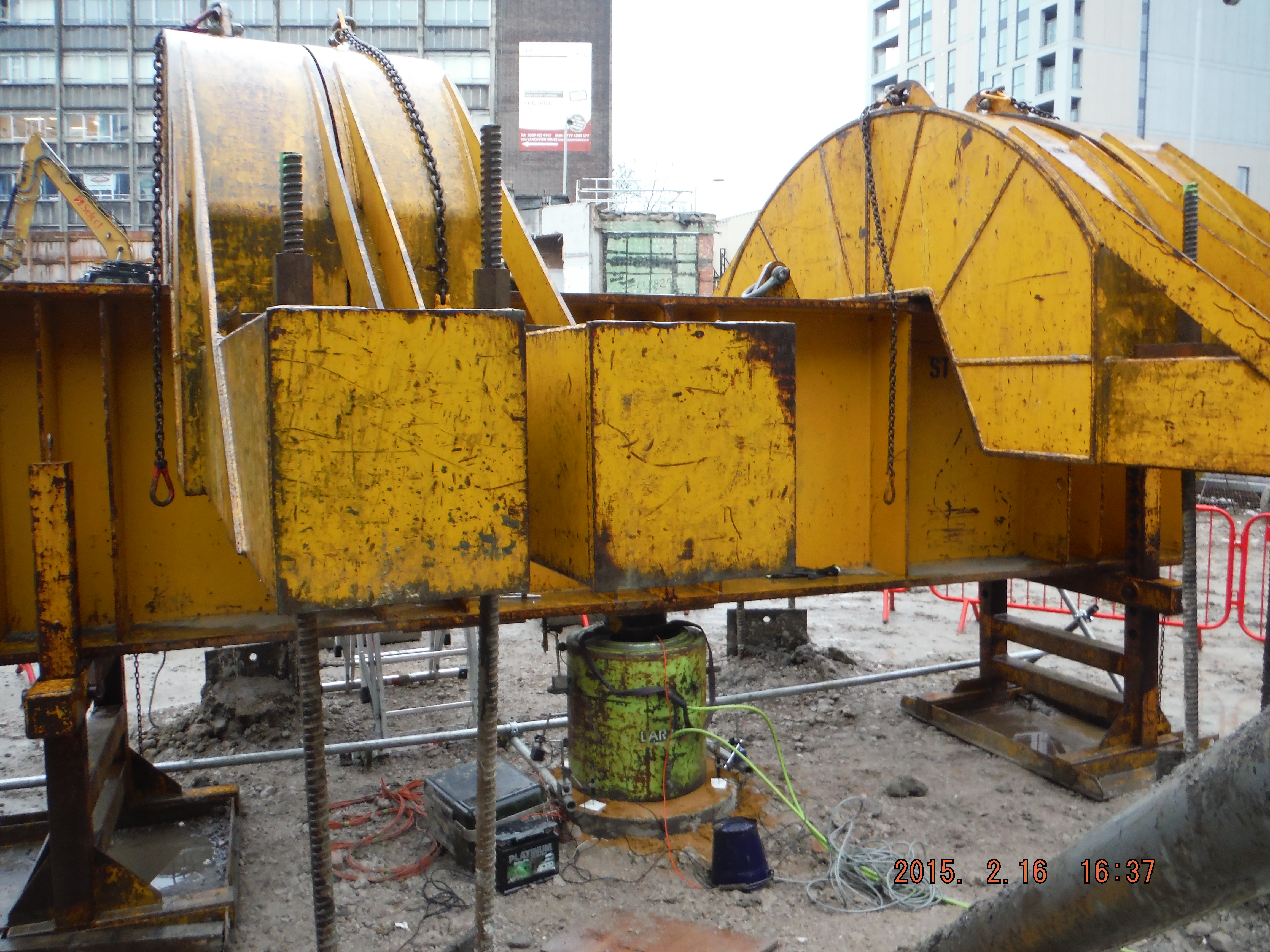
Pile load test. Test to 10MN or 75mm settlement.
There are two proposals for the load bearing piles:
- Individual large diameter piles (41no 1500mm diameter rotary under bentonite)
- Raft foundation (comprising 124no 750mm CFA piles).
The confined nature of the site means the bentonite option is not preferred because the amount of equipment would mean little else could happen concurrently onsite. Therefore the raft option is likely to be adopted, notwithstanding the outcome of the load bearing test, although it will mean excavation around the piles is pretty tight.
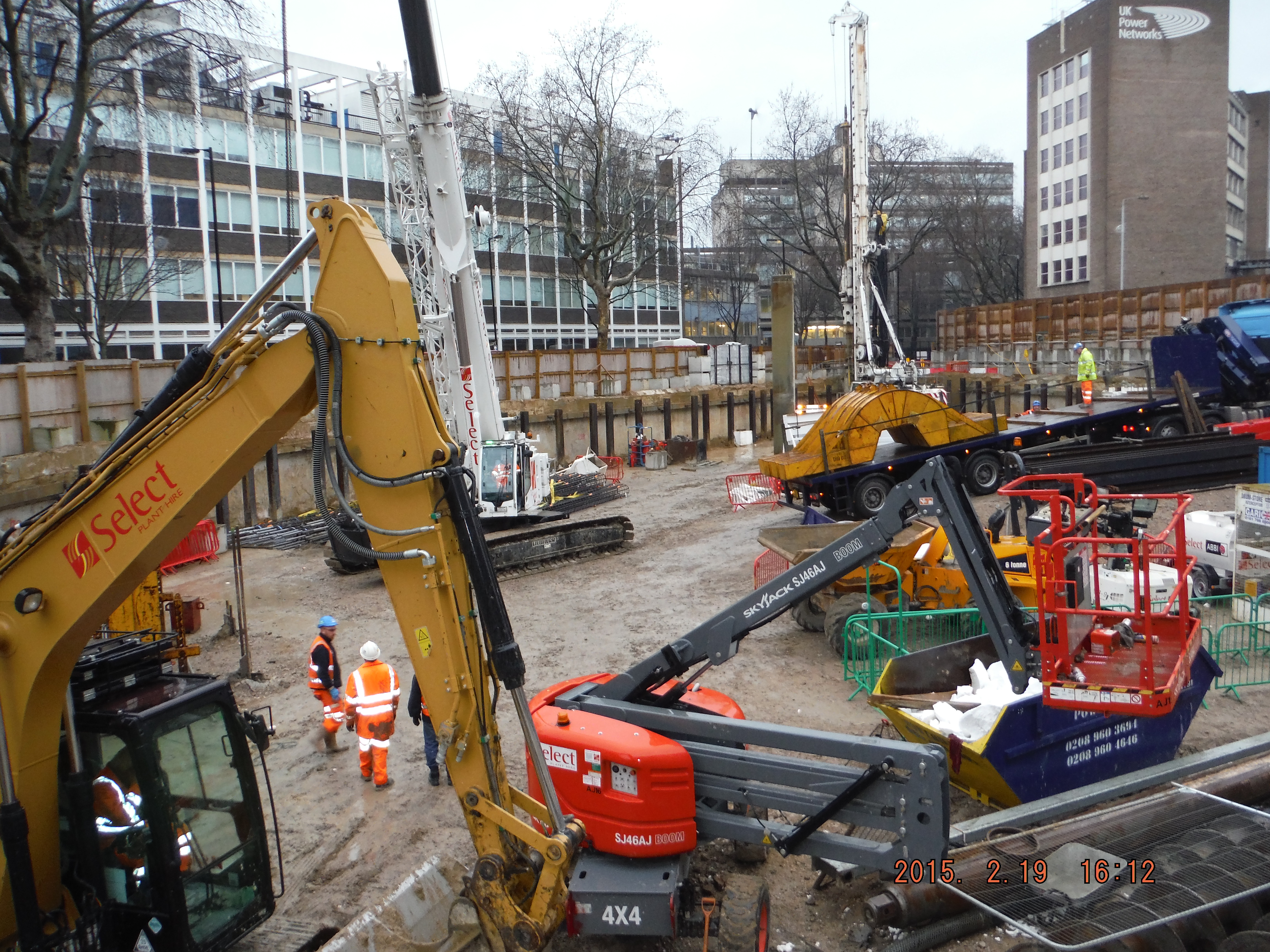
Sustainability. Laing O’Rourke are keen to demonstrate adoption of the Construction Logistics and Cycle Safety (CLOCS) initiative. It was brought home as I read an article in the Evening Standard which talked about the death of a cyclist after being hit by a HGV yesterday

Evening Standard reporting of cyclist death
The statistics point to HGVs being responsible for a high proportion of accidents considering their number compared to other road users. Furthermore, the HGVs were often construction vehicles such as tippers or mixers. I then picked up the NCE magazine to is see an article on “Cyclists’ safety is now critical”. There are levels of adoption of CLOCS going from using CLOCS compliant supply companies (see photo below of tipper with side protection rails and warning signage) to running Construction/Cycle days where cyclists can come and get a mini bike service and have a chat about cycle safety. The question is how is this best achieved on this site to show adoption of the scheme, especially as the site is adjacent to one of Boris’s cycle superhighways.

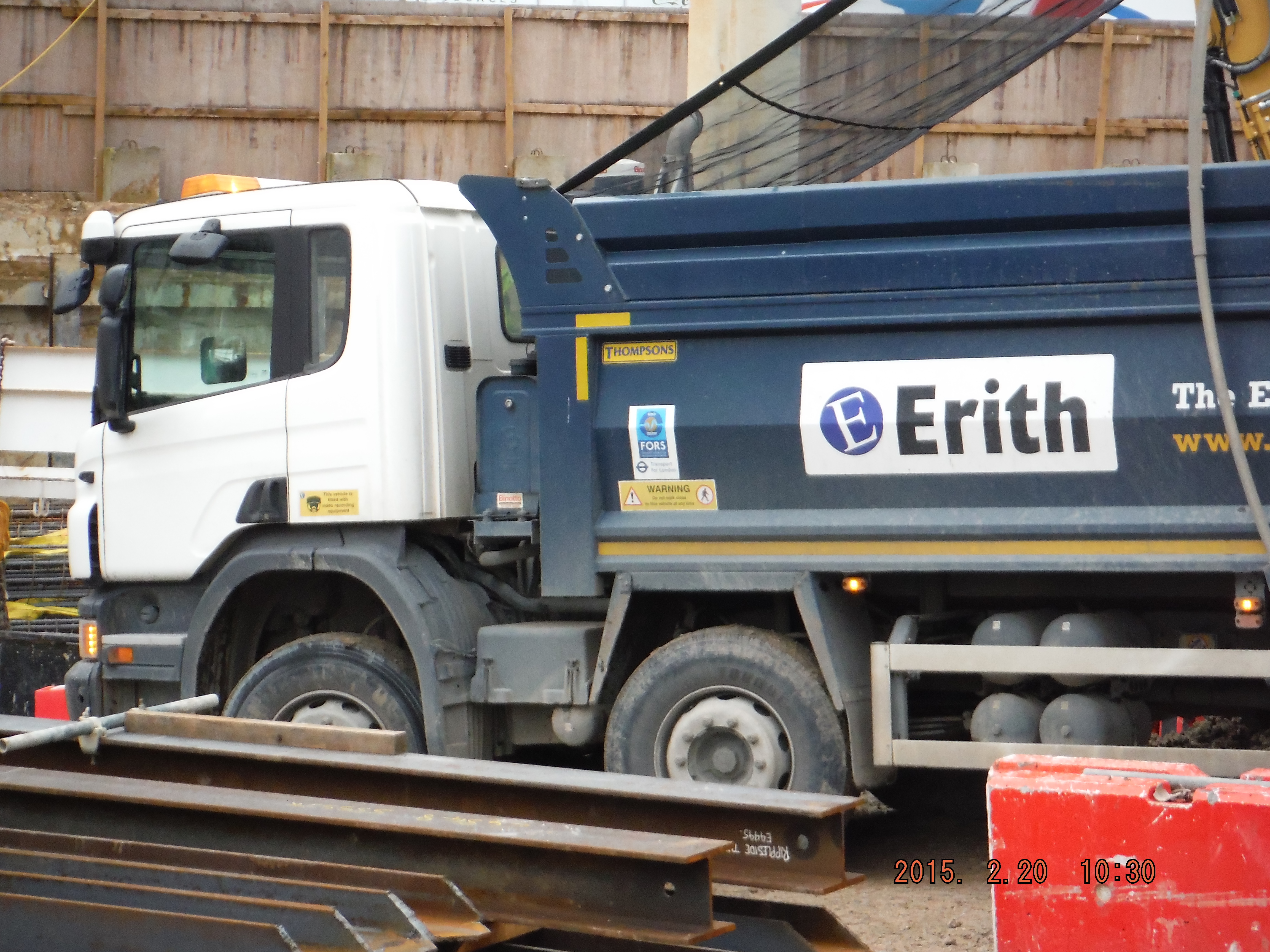
CLOCS Compliant tipper vehicle on site
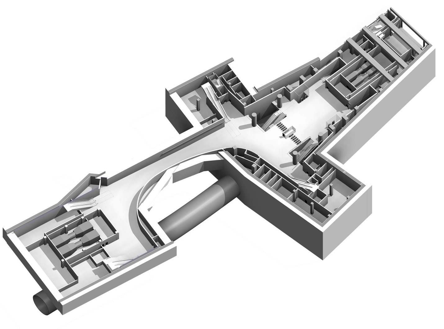
The digital age. At this stage of the project the understanding of how best to implement BIM and realise the benefits of digital engineering is yet to be determined. There have been some point cloud (3D image survey) productions of the site (see below) but how this can be advanced is being established. The Laing O’Rourke Leadenhall Project (Cheesegrater) modelled the construction process of the whole building to refine the method in order to make it more efficient. Other advantages of digital engineering include cost and time savings by being able to demonstrate exactly what is required and the sequence in which the works would need to be carried out. At a more refined level, 3D modelling of reinforcement in the capping beam is an area which is likely to be explored due to the variation along the length of it on this particular site, not to replace drawings but to be used alongside them. The capping beam is an area I am to be responsible for so more to follow.
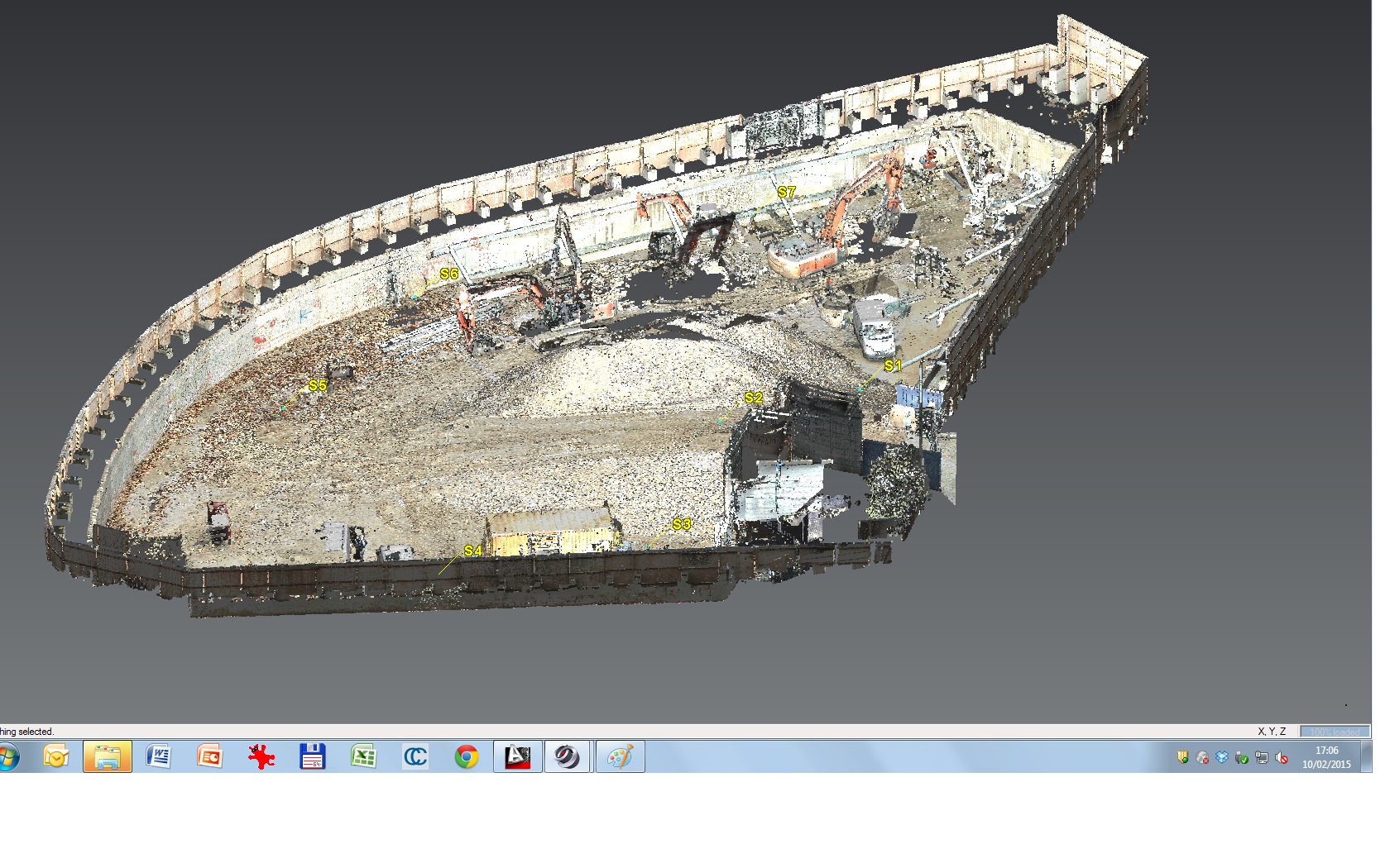
Point Cloud Survey of the site.
What the hell is 6F2?!
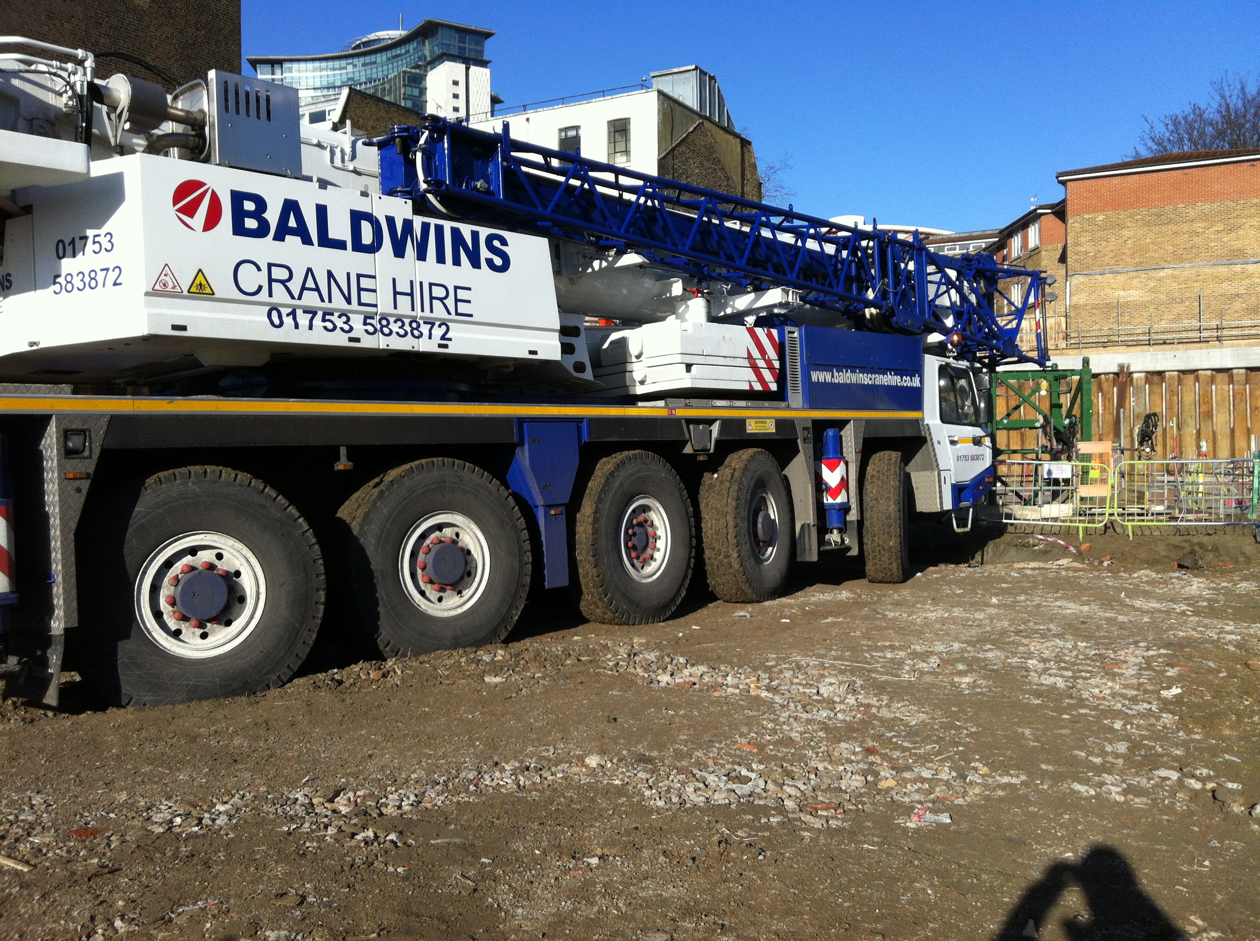
It’s a been a bit of a crazy week, and it’s all P C Harrington’s fault! So much has happened it’s difficult to pick one thing to chat about.
I could talk about this…
I could talk about this…

But instead I’m going to talk about fill.
After the nightmare of the sinking crane on Tuesday (see above), I have been keeping a keen eye on the construction of the mobile crane base for the construction of our second tower crane (we have 5 in total!). The base is to be 450mm thick. Laid in 4 layers. Each compacted with 3 passes of the roller onsite.
First of all they laid it far too thick. Then they didn’t realise that a roller is categorised by its mass per metre width. These things are forgivable. What followed is not…
About two months ago I was halfway through Rhubarb Creek writing about how the 6F2 would be compacted by a certain number of passes of a vibratory roller. At that point I didn’t really understand what 6F2 was (sorry Richard!), but now I do. It is a granular fill with a very specific grading curve. It is not:
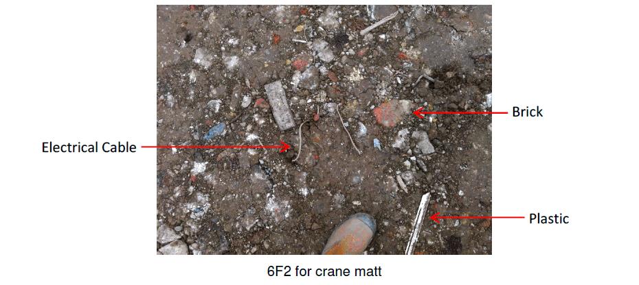
So I explained this to them. They said they would pick out the bits, compact and make sure it didn’t happen again. This morning I found this:
![IMG_0720[1]](https://pewpetblog.com/wp-content/uploads/2015/02/img_07201.jpg)
![IMG_0717[1]](https://pewpetblog.com/wp-content/uploads/2015/02/img_07171.jpg)
Plastic Wood
Now while this is fairly funny and a bit annoying for the bloke who is picking all the crap out of it, it’s not great for the company. They’re paying for 6F2 and they’re not getting it. The quality assurance process they should have in place they don’t.
So we’re working with a company who are running late already (we’re only 2 weeks in), they’ve already had an accident (see tipper above), and their workmanship is shoddy (see last weeks blog). They’ve got a bad enough name here as it is, so why are they accepting this? Probably the same reason why we hired them in the first place. The fill is like the company, a bit crap but bloody cheap!
At the end of my second week I have learnt an important lesson:
IT’S ALL ABOUT MONEY!
MPDS and Interview Prep
Brendan and I attended an IMechE industry contacts seminar in Aberdeen yesterday and it was predominantly about the Monitored Professional Development Scheme (MPDS) but it finished with a presentation from one of the interviewers for CPR in Aberdeen.
The bottom line is it has made me feel much more confident about going for CPR later this year.
This is most useful to those going for CPR with the IMechE and also PEW as an organisation. However, I hope that there are a few useful snippets for everyone.
I will describe the key agenda points and the important points as I see them.
Agenda
Introduction – no synopsis required and the only key point is that the IMechE website now has an ‘on demand’ facility that allows access to lots of online videos of conferences and seminars from around the world.
Tips for preparing for an MPDS accreditation visit – The title is self-explanatory so I will just go into some of the key points:
- PEW is not suited to the MPDS at all. It takes a minimum of four years to complete the scheme and it is aimed at new engineers joining a company. It is absolutely the right thing to continue with the standard application form approach and students on PEW should not be completing MPDS online.
- Over inflated scores of competencies is not helpful – to have a 3/3 across the board when you clearly haven’t reached that level is a red flag. Should the candidate then fail CPR it is difficult to re-rate and develop. Mentors should scrutinise competency ratings and pick them up prior to exposing to the IMechE.
- Media attention. There should be more of a big deal made of those successful at CPR, both for the applicant and the mentor. Many companies employ a financial incentive but this would not work for PEW. However, increased media coverage may be helpful and is something that could be developed. The key part is that there needs to be more of a celebration of achievement.
- A good thing to put in your E competency on the application is that you are a volunteer to be a mentor. The IMechE are short of mentors and the panel look favourably upon this.
Running and MPDS scheme – This was from the perspective of the Royal Dutch Shell MPDS scheme administrator. Most of his points were not relevant to PEW but it was clear how much effort these other companies invest in CPD for their employees. He suggested that mentors should not have the same background as the candidate so it forces the candidate to explain things properly and it is also beneficial for the mentor to read about different subject matter. I appreciate that this would be difficult for PEW.
Professional review interview – This is where the real gems were. It was a presentation from David Baker who is a panel interviewer for those taking CPR in Aberdeen.
- The application. It is competence based so do not just list a career history but describe how you have achieved the competence.
- During the interview he expected the applicant to do 75% of the talking.
- Interview lasts 45 minutes:
Introduction 2 minutes
A, B, C and D competencies 20 – 25 minutes
E competency 8 minutes
DAP 5 minutes
Closing comments 2 minutes
- He went into more detail for competence E. You should cover the following:
Code of conduct. Read it and equate it to your organisations code of conduct.
Examples of continuous improvement. For example, this could be new technology that you have implemented or a new maintenance regime you’ve instigated.
Environmental responsibilities. This could be considering HSE aspects.
Continuous CPD. Annual appraisals, courses you’ve been on etc
Promote engineering. Primary engineer for example.
Ethical manner. You won’t need to provide evidence of this competency until 1 Jan 16 but it could be useful to do so. Mark Hill (hobbit108) posted a useful piece on this in an earlier blog.
- Talk about things as “I did this” not “We did this”
- The sponsor is key to scrutinising paperwork, we get this after AER6.
- There should be mock interviews. I know the civils have this but I’m not sure how formal it is for the E&M students. I know that Imran very kindly offered to come back and run them for our course before he left and I will be chasing him to make good on that promise.
- Take in photos or calculations that you can talk about, especially if you’re the type to get nervous in interviews.
- You need to have three out of the five competencies graded at 3/3, with the other two at 2/3.
Key challenges to passing CPR:
Not providing evidence of A + B competence
Not being able to talk about the detail of what was in the application.
Another thing that I took from this is that PET students are different to the normal CPR candidate. They tend to be more discipline based with much less management experience.
From a personal perspective, I feel that my previous military experience plus phase 1 and my experience at BP has certainly given me 3/3 in C, D and E. I think I am on my way to a 3/3 with the A competency and I will be okay reaching a 2/3 with the B.
I also think that the role of mentor is very important. For those of us going to Staff College it could be a useful way of maintaining the CEng flame. I for one would be willing to look over someone’s application, their competency record as they build it up and if I’m available I would help run a mock interview next year.
