Better late than never.
This blog has been sat on my laptop awaiting publication for some time and whilst now out of date I think it is still worthwhile publishing. Much of this also formed the basis for AER 3 so you can exit at this stage if you have read that document! I wrote this towards the end of my time at Graham Construction in mid November.
I have reverted to publishing this blog as my brain is aching after being set a timber and steel construction tutorial by the senior chartered structural engineer, who’s office I have been moved into and sit directly opposite. Joy.
Blog from mid-November.
The last few weeks have seen me of focussing on trying to eliminate a few outstanding development objectives that I need to have achieved by the end of phase 2. I have been concentrating less on the physical construction of structures that dominated my previous time on site and more on the commercial and managerial aspects of leading up to the construction activities.
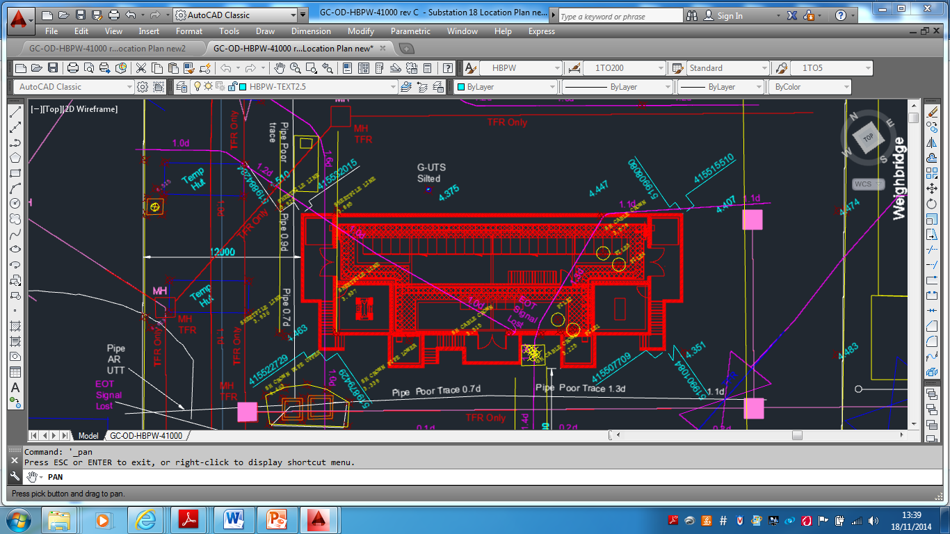
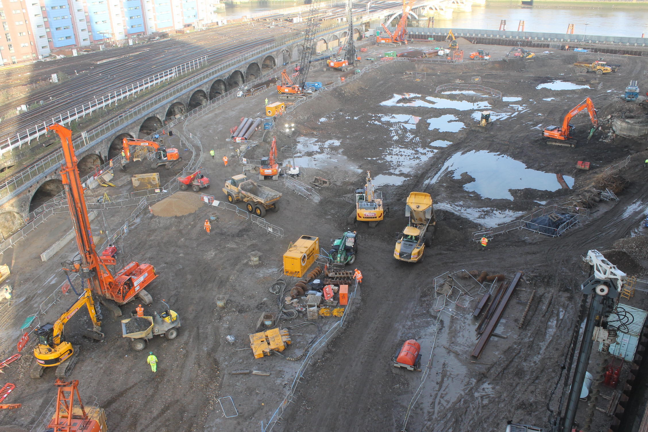
Sub Station 18.
I have mentioned on previous blogs that I have been given an independent command of a small sub-station at the east end of the docks, a couple of miles from the current IRFT site. Whilst not the largest project in terms of real estate and value it has allowed me to take a project from proposal to the early stages of construction. I will not see it completed but have assisted in building the 2 other substations on the IRFT site and as such it will allow me to hit the DO’s I am short on.
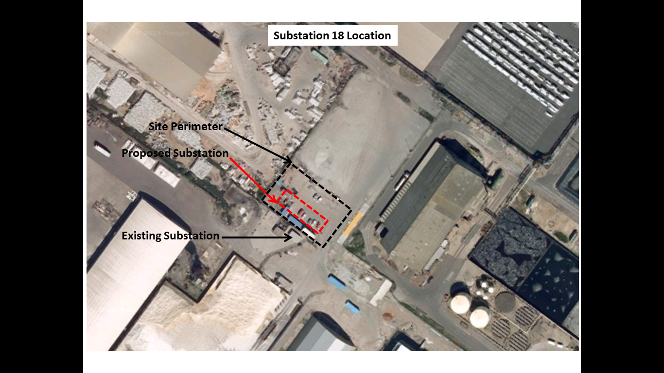
Sub 18 Location
Proposal.
The new substation is required to replace an existing substation situated north of the chosen site that was subjected to extensive flooding during last winter’s tidal surge up the Humber Estuary. The location and pre-tender service drawings have been provided by the client and the design has been produced by the consultancy for the QS’s to produce a tender price (approx. £300,000). The contract has yet to be awarded but ABP were keen to conduct a site investigation in the proposed area in the knowledge that the location is a well-used brownfield site with a legacy of industrial use. There are a number of documents out there on how to conduct a site investigation. I referred to the AGS (Association of Geotechnical and Geoenvironmental Specialists) for guidance and used their checklist for site investigations to keep me straight. http://www.ags.org.uk/aboutbusiness/bestpractice.php
It is likely that that the contract will be either a variation order to the IRFT contract or a negotiated contract due to the specialist skills accrued by Graham in construction of the previous substations to the ABP specification. This would reduce the costs of tendering and has allowed for early contractor involvement. Whilst the competitive element is reduced the relationship between ABP and Graham is sufficiently strong to allow for robust negotiations. Until the contract is formally awarded all the works I have conducted have been charged to ABP through Operational Record Sheets but if Graham win the work the cost may be negotiated into the overall tender price for the construction due to the increased rates on an ORS.
My first task was to hold a meeting with the client to firm up this detail and then walk the site with them to understand their intent as part of the pre-tender process. I then wrote a RAMS covering the set up and establishment of a new site, reviewed the substation construction RAMS from the previous builds, drafted a programme of activity for the set up and works and completed a number of permits for excavation and working around live electrical services.

Sub 18 Programme of Activity
Feasibility.
Desk study.
My pavlovian response to approaching and shaping the SI was ‘what are the risks’ both technically and from a commercial prospective, financially? The pre-tender service drawings provided by the client were clearly dated and inaccurate but gave a good enough picture of the number of services that I may encounter during any investigation works. This led to the early conclusion that the main risks would be to the cost of the project in dealing with the services and not necessarily the risks posed to the design by the soil properties. This notion was strengthened by my previous experiences during my construction activities at the IRFT having had no issues with the ground (apart from a few broken piles!). Whilst the preliminary design was completed I could directly influence the final design through the findings during my GI. The structure itself whilst over 8m in height, has only the cable pits and ground slab, approx. 2m worth of structure below the current ground level of 4.4m AOD. Despite my confidence I did know that it was important to understand the groundwater regime and so got onto the British Geological Survey’s website to locate the nearest borehole to my site. The boreholes were 1947 trail water boreholes and indicated a rest water level of approximately 3.0m AOD close to my site. This made sense given the proximity to the docks, mean tide level and previous experience. The boreholes also indicated that the surface strata comprised top soils with black mud followed by varying depths of stiff clay and pebbles. The stiff clays feature from around 3.5m AOD, approximately 1.0m below the ground surface and due to the water level would demonstrate undrained fine grained material properties. This gave me the confidence that the strength during any excavation work, unloading the soil (short term) would be sufficient. Due to my previous excavations on the main site, in similar soil conditions, and the obvious low permeability I was also confident that any water seepage could be controlled by the standard 2” submersible pumps. This information furthered my notion that the risks in the ground were unlikely to come from that material properties or the groundwater regime. It was clear to me that the risks would be in what we physically found in the ground both to the excavating team and the cost.
The next phase was for me to check the historical records and identify any existing services which was easier said than done. The historical drawings provided by the client were dated and only included recent client constructed additions to the site area and not a great deal of legacy information. However I complied what data I could find and found that the best results were obtained from my site walkabout to ID manholes, resurfaced channels, lighting , inspection chambers etc and then chatting to all the ‘old boys’ working in and around the site who provided a wealth of information having worked on the docks their whole lives. This was all compiled into a working document as the initial stage of the GI report.
Design. Phased Investigation.
Non – intrusive Investigation.
Once I had gathered all this information I contracted SUBSCAN (Sub-surface survey contractor) to complete a GPR survey of the entire area, based on my previous experiences (HV strike) and the proximity to the existing substation to be replaced. Once again the GPR survey proved its worth as a substantial number of unknown electrical and non-electrical services were identified that were not shown on any drawing or identifiable from the site walkover I confirmed the location of these services with the CAT SCAN and then did my best Art Attack effort with about 5 tins of spray to highlight every known service prior to any intrusive investigation.
Intrusive Investigation.
The next phase was to dig a number of trial holes and slit trenches to expose and confirm the services, their condition and generate a solution to dealing with them. This is where the true extent of the services was revealed and we found a whole host of legacy pipes, cables, piles, manholes, concrete chambers, railway lines etc. It took a couple of weeks to actually expose the full extent of what we found in the ground as the more we looked the more we found. Even after a thorough desk study and non-intrusive survey I still found unrecorded services but we had no H&S incidents. I also took samples for contamination analysis and sent them to ESG for a full suite of tests. At the end of the intrusive investigation it was clear that the clients proposed sub-station location would involve a substantial amount of ground works to accommodate the structure. This work included temporary diversion of 5 electrical cables, removal of a 20mx5mx 3m deep concrete chamber built inside an insitu steel pile cofferdam housing 2 x Victorian cast iron power station water cooling pipes (500&750mm), a railway line, 8 PC RC piles, 4 cast iron water pipes and 2 associated manholes and a number of drains. None of this work was expected and would be added to the tender cost.
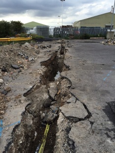
Sub 18 – Intrusive Investigation
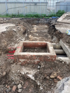
Sub 18 – Intrusive Investigation

Sub 18 – Intrusive Investigation
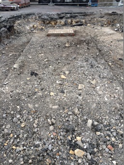
Sub 18 – Intrusive Investigation
Geological Report/Interpretation.
Due to the speed of the discoveries I kept a drip feed of information flowing to the design co-ordinator and the clients representative, holding a couple of meetings to discuss my findings and suggesting the best way to proceed. At the end of my intrusive investigation I put together a powerpoint presentation and CAD drawing to summarise the points I had written in the geotechnical report that I had been concurrently writing on the site. I found that this was the best way to portray my points clearly without having to trawl through a full geotechnical report. I recommended a shift in the substation location that would minimise the amount of work required to relocate the services thus reducing the cost and construction time. I plotted this out on the ground and walked the client through the proposal. I outlined where I thought there were still risks to the construction and design which were predominately focused on access for construction and subsequent installation of the transformers and the undermining of the various services to get all the HV lines into the substation whilst maintaining the minimum 1m cover. I also fed these point back to the design co-ordinator.
Sub 18 – Results of Non Intrusive and Intrusive Investigation

Sub 18 – My revised location republished by the designers for client approval
Detailed Design.
The detailed design was published last week and the client has now completely revised the location. The substation has been moved to the west of the current location, inside a restricted fertiliser handling facility. The driver behind this decision is the expected cost of the ground works required, even with my revised location, and the value of the site for future commercial use, when compared to the new location. In my opinion there will not be a saving in the ground works as the new location is likely to be as service ridden as the previous but I suspect the future proofing of the location and cost of land is the main factor. This is especially the case when you consider the works we have subsequently conducted to re-instate the trail holes (backfill, 150mm aggregate, roadsaw to cut straight edge, tarmac subcontractor to re-surface, etc) not to mention the asbestos I found and have subsequently had removed on the second site walkover.
So I am now repeating the process. I have edited my RAMS for site establishment, completed my site walkover, amended the desk study and re-contracted sub-scan who are in today.
So what did I learn?
Despite being slightly frustrated at having put in so much work on the initial site for it to be moved, I completely understand the long term commercial consideration on future land use and rental potential. However I am convinced that greater analysis by the client at the proposal stage would have highlighted this consideration and saved them a not insignificant amount of money on the work to date. I have yet to receive the updated costings from the QS team, but it is likely all the SI and subsequent reinstatement work will cost approximately £40,000. This is not including a figure for the SI work still to be conducted for the new location and is a significant additional cost for a £300,000 project. In the green, it’s not even a question 4 moment, as the situation hasn’t changed, in this occasion the fault lies with the BGE as there has clearly been an inadequate IPB. Sorry for the stinking chat.
When given the task, I looked for a handrail and was surprised to find no national specification and method of measurement for site and ground investigations. It would have been useful to have had a one hit document based on current ICE specifications but augmented to accommodate the philosophy of Eurocode 7. There are any number of GI handrails available written by a host of private companies, local authorities and geotechnical experts but I was surprised by the lack of a coherent national document especially to guide non geotechnical engineers through low level site investigation. Exercise Cofferdam formed the basis of my knowledge on the compilation of a geotechnical report.
This leads onto my next point as it struck me as the type of activity I may undertake when back in the green. Whilst not hard core geotechnical engineering involving interpretation of material properties and utilisation of that data for design, the nature of the investigation and commercial considerations have been an important lesson. I can envisage similar circumstances where it is unlikely that we will have a true geotechnical engineering specialist available but there is the requirement to assess the risks in the ground , both physically and commercially and communicated those accordingly to a client.
Now back to my web buckling checks…..
Wrapping up at PCH
PCH
The last few months have been amazingly busy with the project becoming more intense every week as the time is dramatically running out and a number of items are still not designed. As a whole the basement, the area I look after is quite lucky as it does not get as affected by superficial changes which the Architects seem to change with no consultation with the engineering consultants and most of the user groups are not interested in the back of house areas so all good for us in the basement!
 The photo above is a photo of when I first started on the project and its not until you look at the photo below to believe how much work has happened. This does not really show how much the basement has changed considering when I first started in the basement there were no services installed other than a section of Syfonic drainage in the corridor of death.
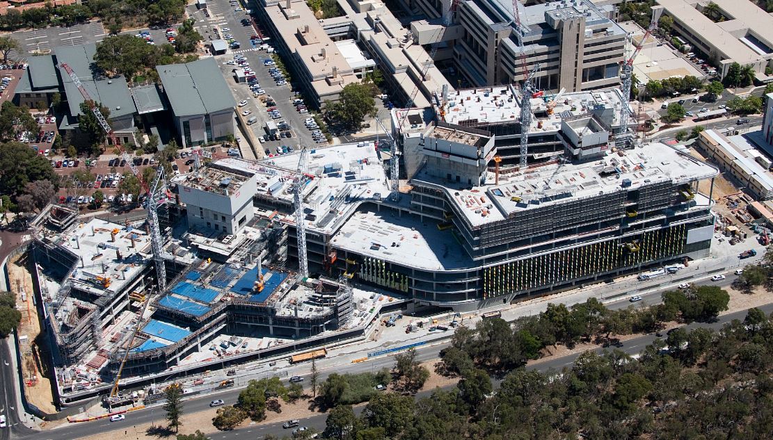
 The hospital as it stands at the end of November.
Milestones
The major miles stones which have been achieved in the last two months:
Central Communications Room 2 handover which alone I had substantial tactical, operational and strategic influence and effect, this alone had damages of $180,000 a day and total worth $4 Million and it was delivered 2 hours early!! The amount of information and technical knowledge learnt during the process of building CCR 2 has been amazing, I have learnt about all the aspects of Tier 3 Comms rooms and to my astonishment I caught the professionals out a few times.
![IMG_1809[1]](https://pewpetblog.com/wp-content/uploads/2014/12/img_18091.jpg)
The official handover to the State (the chaps in the green hard hats)
Connection of Chilled Water from the Central Energy Plant, this was a major milestone which I personally organised all of the works involved (including all the safety paperwork, works on a Sunday etc) with the Mechanical Subbie and all liaison with our Client the State. This was achieved in a safe and controlled manner and all within the time period which did not have any knock on effect to daily works on the Monday. The only disappointing part of the works was that the work was achieved but due to Strategic level politics between JHG and the State the Chilled water still has still not been turned on.
![IMG_1663[1]](https://pewpetblog.com/wp-content/uploads/2014/12/img_16631.jpg)
A subsidiary side of this main work was the connection to the CCR 2 pump room which has its own set of heat exchangers and pumps to ensure a mechanical separation from CCR 2 and the main chilled water system due to one system running at 1500kPA and the other 400kPa. This system incorporated all the BMS side and was fully functional on the delivery date of CCR 2 which included flushing of the system which again I learnt a great deal, chemical endorsement by the water corporation and water treatment for a tier 3 communications room which included a temporary Reverse Osmosis supply.
![IMG_1761[1]](https://pewpetblog.com/wp-content/uploads/2014/12/img_17611.jpg)
Hydraulic Plant room which had a milestone deadline of end of November fortunately was in the full control of Christopher Contracting the plumbers who are exceptionally good subcontractor. We had to have a few technical workshops which I managed with them and our engineer consultants NDY. The most impressive part was the modular tank manufactures which came from Malaysia who were exceptionally professional and built all three tanks in three weeks, they could of shown the Aussie some work ethics!!
![IMG_1973[1]](https://pewpetblog.com/wp-content/uploads/2014/12/img_19731.jpg)
Plant Room 10 was meant to be completed on the 10th of December 2014 but sadly Fredon is like that Sapper that you are told about before you become a Troop Commander who takes up the 90% of your time and is the worst performing. We achieved the Chilled Water date of 25th November 2014 but the high temperature pipe has all been manufactured but not installed yet because they still have not got sufficient paperwork as per the specification foe the pipework to start to be installed. The quality issue with Fredon is still a major problem and the latest incident is their shell and tube heat exchangers which have poor safety in design and maintenance accessibility.
![IMG_1975[1]](https://pewpetblog.com/wp-content/uploads/2014/12/img_19751.jpg)
Life
As mentioned in the last Blog Hannah signed us both up to the Mandurah 70.3 Ironman, fortunately for us it was the hottest day be have had since we have been in Aus at 36 with a recorded temp of 45 off the tarmac. It was a great event overall and I had a great swim and bike but the run was brutal in that heat but completed in 6 hrs so happy enough. Hannah has just got back from National’s in Brisbane for Modern Pentathlon and came 4th so she is chuffed with that and is competing in Melbourne in January so hopefully a top 3 there.
![IMG_1733[1]](https://pewpetblog.com/wp-content/uploads/2014/12/img_17331.jpg)
I have had a fantastic experience and learnt such a great deal whilst being part of the basement team and unfortunately got slightly too involved at times and my work/school work balance lapsed and the blogs have been missed at times but with New Year ahead you will be hearing some more from me, have a great Christmas and New Year.
Riyadh Metro – Ground Water Risk, again!!, but different!!!
Now at the end of my second week with Arup I have found a desk, computer and even taken some time to find the library check out some books and remind myself what a bending moment is. Not sure why I am surprised but a have found copies of most the books we were issued on course either in the library or actually being used by engineers around the office.
I have been assigned to the Riyadh metro team and once again find myself looking at trains underground.
Project in brief
The Riyadh Metro is part of a wider scheme to regenerate the public transport system around the capital city of Saudi Arabia called the Riyadh Public Transport Project (RPTP). The metro system is to be a rapid transit system designed to reduce congestion within the city due to the rapid growth in the size of the population of Riyadh within the last 10 years. Construction of the metro system began in April 2014 and is due to be completed in 2018.Once completed the Riyadh metro consist of six lines totalling 178km of track and 85 new stations. Arup have been employed as lead design consultant by BACS consortium consisting of Bechtel, Almabani General Contractors, Consolidated Contractors Company and Siemens. At Arup the Riyadh metro team is responsible for the design of the five subsurface stations along the Green and Blue lines. At my time of arrival the 30% concept design has been completed and the team are now turning their attention to the 60% detail design phase. I have been assigned to the team looking at station 1F2 which is considered the most complex of all the stations. The complexity is due to the interface of already existing buildings, a main highway (under which the station is to be built), a flyover and testing ground conditions.
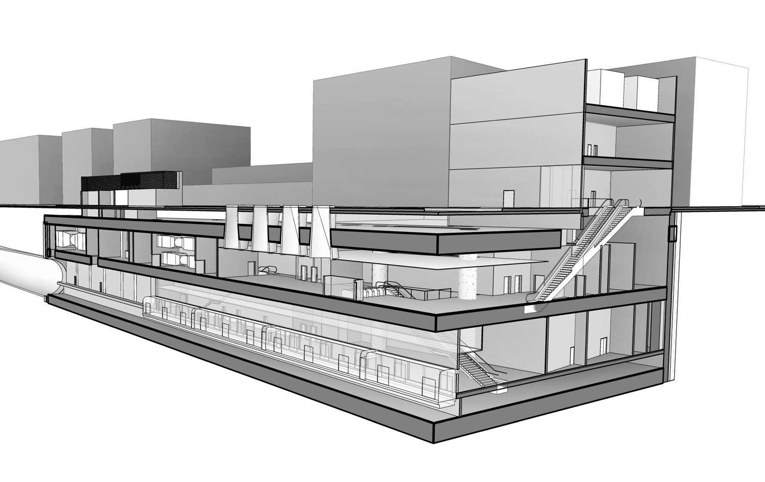
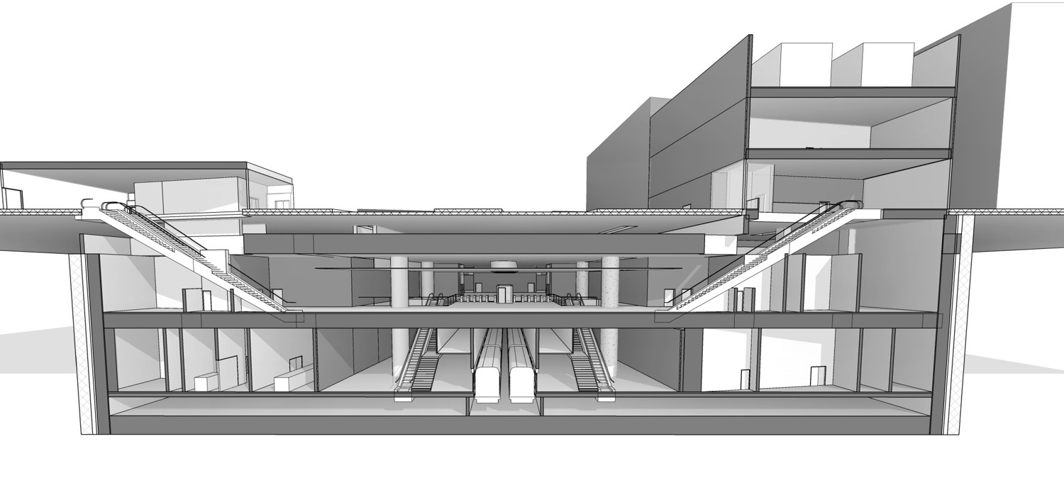
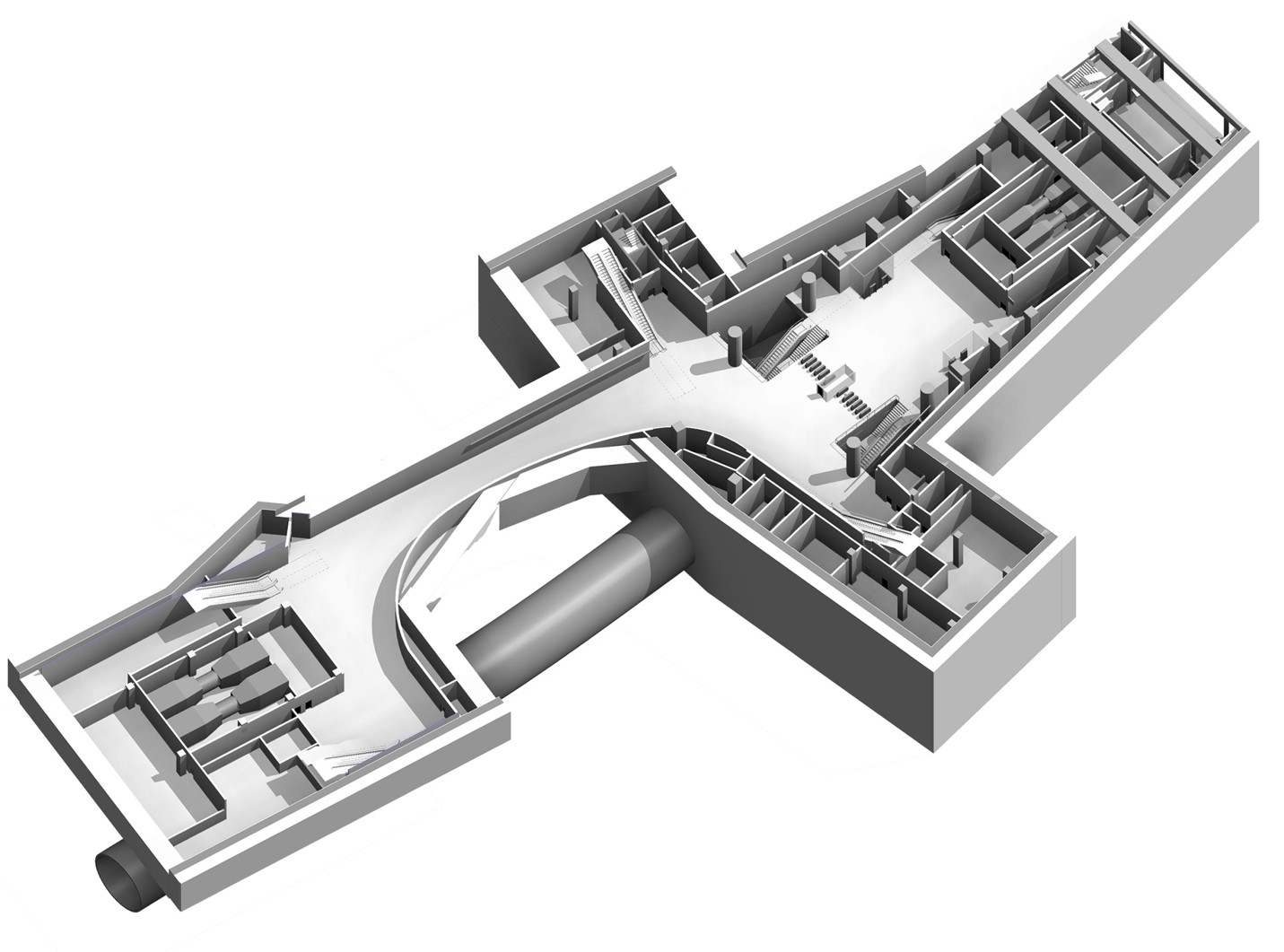
Fig 1. Station 1F2 structural model.
Construction Method: The construction of 1F2 is to be a bottom up construction unlike the Liverpool street station which was a top down construction. The use of a secant pile diaphragm wall with tension anchors into the soil behind the piles will be used to maintain the excavation. The structure will then be built from the bottom in a conventional method.
Soil Conditions: Although not read into the detail the ground conditions on site are set to be quite different to Liverpool Street. The ground is predominately course grain gravels, sands near the surface with more consolidated soils at depth and ultimately layers of rock.
The Engineering Risk.
Ground Water: The main engineering risk identified in this case has been ground water due to confined aquifers and a high water table and high permeability soil. The high permeability of the soil combined with an wxpectation of large fissure will result in a high flow rate of ground water which will fill the excavation and pose arisk to life or at the very least make conditions unworkable.
Settlement: Any attempt to lower the water table will also alter the voids ration and cause settlement of surrounding soil and poses a significant risk of causing damage to surrounding structures.
Solution
Reduce the ground water flow. Ground water flow (Q) occurs when a change in the ground water regime sets up an hydraulic gradient (i), i.e. opening an excavation. The greater the difference in head the greater the hydraulic gradient and the greater the flow, however the length over which the water must flow will also affect the flow of water due to resistance caused by the permeability of the soil. As a result
Ground water flow (Q) =Cross section area (A ) x permiability (k)/flow length (l) x (h1-h2)
Hydraulic Gradient (i) = h1-h2 / l
Therefore there are a number of ways to reduce the ground water flow into the excavation, one using a ground water pumping regime to reduce the difference in hydraulic head or increase the flow path by forcing the water to flow further using a hydrulic cut off.
Ground water pumping reduce head difference: My usual approach would have been to design a dewatering scheme to lower the water table outside of the diaphragm wall to ultimately lower the ground water within the excavation. However due to the risk of settlement and damage to structures within the influence zone this has been deemed unsuitable. Therefore de watering must take place within the excavation.
Ground water cut off increase the flow path. In order to reduce the flow of the water a vertical cut off may be used to reach a lower permeable soil boundary or to increase the length of a vertical cut off to increase the length of the flow path and reduce flow. A typical method for achieving this is the use of piles either sheet or RC concrete. The geotechnical team within Arup have opted to used injection grouting at the base of the pile to create vertical cut of. In this case a TMS (Tube a Machete, read tube with holes in it) is inserted through the pile and grout injected in to the soil to fill the voids. The intention is to us a course grain grout followed by a finer grain grout to create the vertical cut off and reduce the dependency on augured piles.
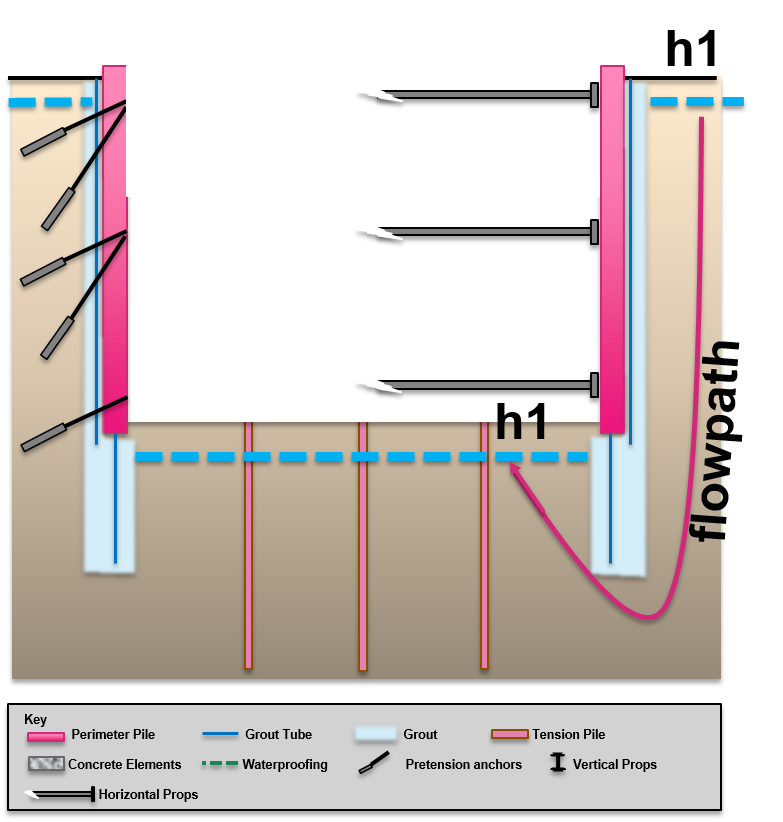
Fig 2. Showing use of grout as a vertical cut off to increase the flow path.
My initial thoughts are that this seems very high tech and potentially engineers trying to be too cleaver. The problem that I raised but apparently has been considered is that the first that anyone will know it has failed is when the excavation starts to fill with water. In this instance it would be too late to increase the length of the secant pile wall to increase the vertical cut off. I stand by to be corrected.
Comments on a post card…..
Lunatic Asylum
On my second day in the Jacobs design office, a call came in from a Brisbane mental asylum for help with an existing air conditioning system. The system was installed as part of a refurbishment of a single story heritage building within the asylum grounds in 2008, and has not worked properly since. The installer has made several return visits to ‘fix’ the system but has failed to do so. As the warranty has now expired, the maintenance team decided to employ a consultant to fix the problem once and for all. I put my hand up to run with the task.
The Task
Design an air conditioning system for the building which uses the existing split units to best effect. The solution must also be feasible to install whilst complying with the restrictions placed on heritage buildings.
Background
The buildings principal use is for offices, and the nature of staff complaints suggest issues with the capacity of the system and with air distribution. Someone, somewhere is either too hot or too cold, and any attempts to fix the problem have just shifted it to another room. I went to recce the job and found that they currently have 3 outdoor condensing units, each with a cooling capacity of 15.2 Kw, on 3 refrigerant ring-mains, feeding a series of indoor head units of varying capacity. It was immediately obvious that the indoor head units were poorly distributed among the rooms, and that there was no outdoor air supply other than natural infiltration. I collected details of the outdoor and indoor units, the room occupancy, noted the electrical equipment in each room and got a feel for the composition of the roof and walls. The site manager provided me with drawings of the building which had room sizes etc.
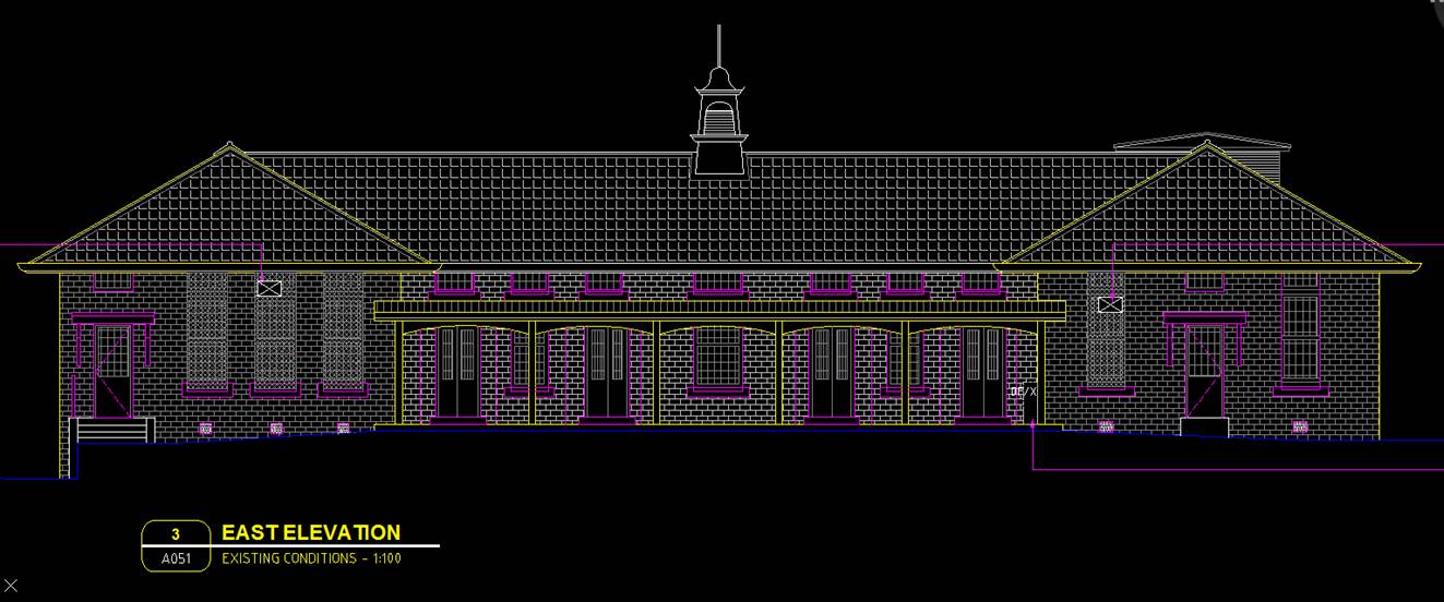
Figure 1 – East Elevation
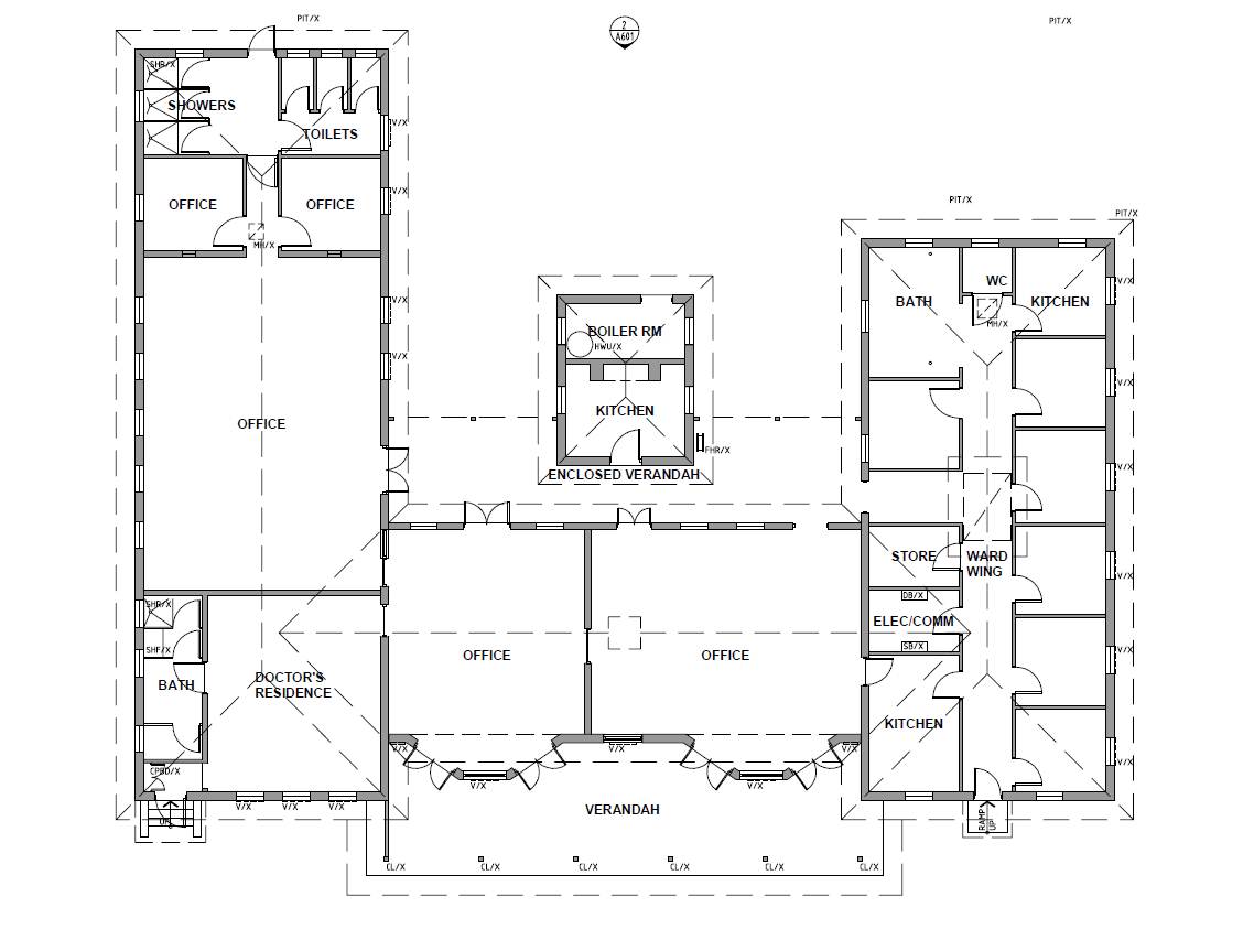
Figure 2 – Floor Plan
Due to the building being heritage listed, the site manager advised that the re-design should to use existing penetrations through the ceiling and walls. This will mean that refrigerant pipes will be visible on the inside of the rooms, and any ventilation will need to use either existing ceiling access panels (of which there are very few) or windows.
Heat Load Calculations
The heat load software used by Jacobs Australian offices is Camel, and is significantly less capable than Hevacomp as it only calculates heat loads. It took me the best part of a day to input the building data using the Camel manual as a guide. The project was an ideal size to learn the software and to figure out the little tricks that help speed up the data entry.
The key outputs from Camel were as follows:
- Individual room heat loads..
- Condenser cooling capacity required per zone.
- The W/m2 per zone, which gives an indication as to the accuracy of the output data – usually in the region of 200W/m2 for an office.
- Coil dew point
- Sensible heat factor.
The rooms are currently grouped into 3 zones, each serviced by a single 15.2Kw outdoor condensing unit as shown in Figure 3 below.

Figure 3 – AC zones and existing Fujitsu head unit layout.
The Camel heat load results clearly showed there was a problem with capacity in Zones 2 & 3, which tied in nicely with the information from the user.
- Zone 1 required a cooling capacity of 17Kw at its peak load.
- Zone 2 required a cooling capacity of 26Kw at its peak load.
- Zone 3 required a cooling capacity of 38.6Kw at its peak load.
So, the problem was three fold; insufficient cooling capacity for Zones 2 & 3, poor distribution of head units within the rooms and no outside air ventilation.
The Solution
Insufficient cooling capacity – Further divide the rooms into additional zones so additional condensers can be added to provide the required cooling capacity. Condensers to be selected form Fujitsu range based upon size requirements.
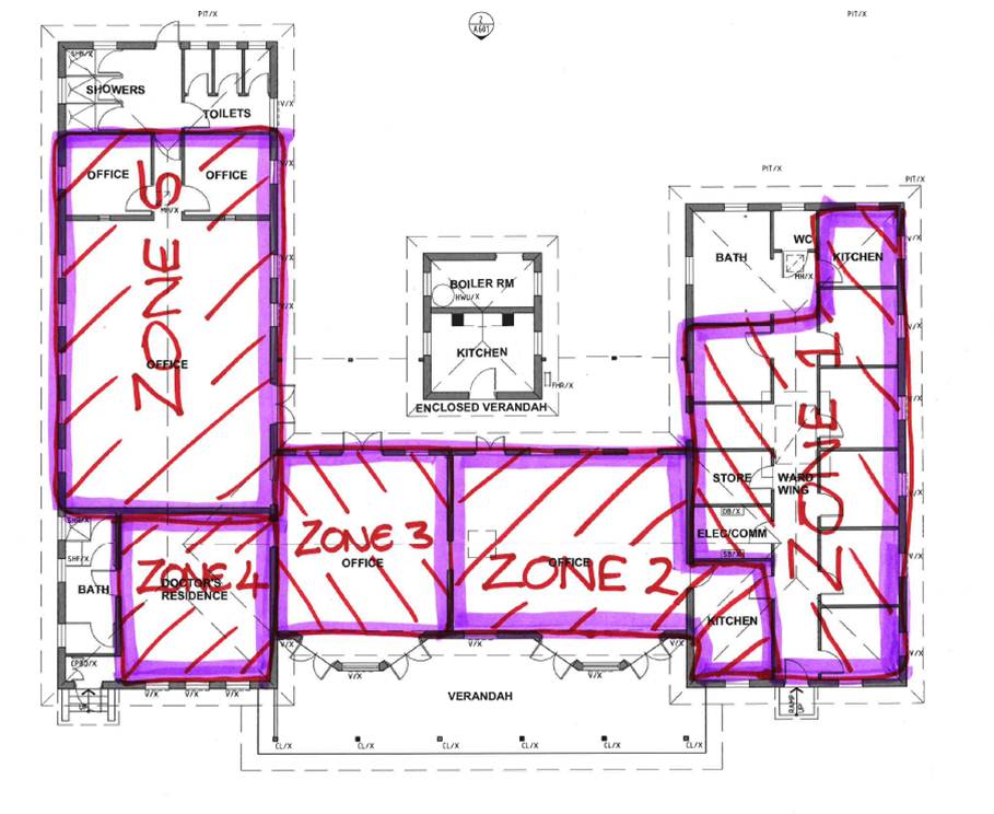
Figure 4 – Revised AC zones.
The revised zones require the following cooling capacity at their peak:
- Zone 1 – 17.0Kw – can utilize existing condenser unit.
- Zone 2 – 13.3Kw – can utilize existing condenser unit.
- Zone 3 – 4.48Kw – requires additional condenser unit.
- Zone 4 – 17.4Kw – can utilize existing condenser unit.
- Zone 5 – 20.3Kw – requires additional condenser unit.
Poor distribution of head units – Re-distribute head units and add units to rooms where current capacity is insufficient. The solution below utilities all but one of the existing head units but has an additional seven units of two different sizes. Figure 4 below shows the re-distributed head units. The purple represents a head unit and the number correlates to a particular unit capacity.
- 7 – 2.15Kw
- 9 – 2.8Kw
- 14 – 3.8Kw
- 18 – 5.4Kw
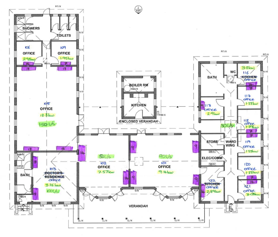
Figure 5 – re-distributed head unit layout.
Ventilation – Provide pre-conditioned air to each of the spaces so as to improve the efficiency of the system and reduce the load on the indoor head units. This is proving to be the most complicated part of the problem in terms of how to provide conditioned ventilation to each space, without any works that could cause problems with the buildings heritage status. The options being considered at this stage are; providing heat recovery ventilators to each room through windows, installing a centralised pre-conditioner in the roof space below the clock tower and ducting to the 5 key spaces (for zone 1 I am thinking to put air into the corridor rather than individual rooms), or a chiller unit with a chilled water loop.
At this stage, my thoughts are as follows; the heat recovery ventilation to each room would be the easiest option but the units are 1m x 1m x 2m and weigh 76kg so mounting them in a window (I cannot put any new holes in the walls due to heritage restrictions) would be difficult; the centralised pre-conditioner would potentially provide the best efficiency but it will depend upon the ceiling space available and flow/return air possibilities through the clock tower; the chiller unit seems overkill for such a small building and would require chilled water to be piped around the building.
I have spoken to a supplier to get and understanding of the options, and have another recce planned for tomorrow to see which options are physically possible….
The Joys of Office work
So I’ve now settled into the Jacobs design office. I’m starting off in the civil infrastructure team. The main things they deal with are bulk earthworks, roads and stormwater (drainage). So far I’m straining my brain in trying to remember all the stuff we did with Richard before disappearing off on Phase 2!
There are a few existing projects on the go, but most of what I have been doing recently is new proposals. These are either in the tender process or pre-tender.
Jacobs structure has marketing and sales sitting separately to the rest of the company. They seem to focus on relationship building with a number of clients – all in the hope of winning work before it goes to tender. For private clients I can understand this, but for government or defence clients that have to go to tender I’m not sure how beneficial this is? The hope is that they will be asked to complete the prelim designs for a client, then when the invitations to tender are sent out they are already one step ahead of the competition. Despite my scepticism it seems to work well for them. This year the infrastructure group in Brisbane have won $50 million of work from one client (the department for transport and main roads). This is 49% of the total revenue for the Brisbane office.
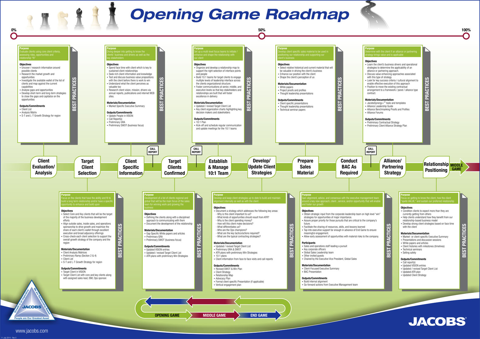
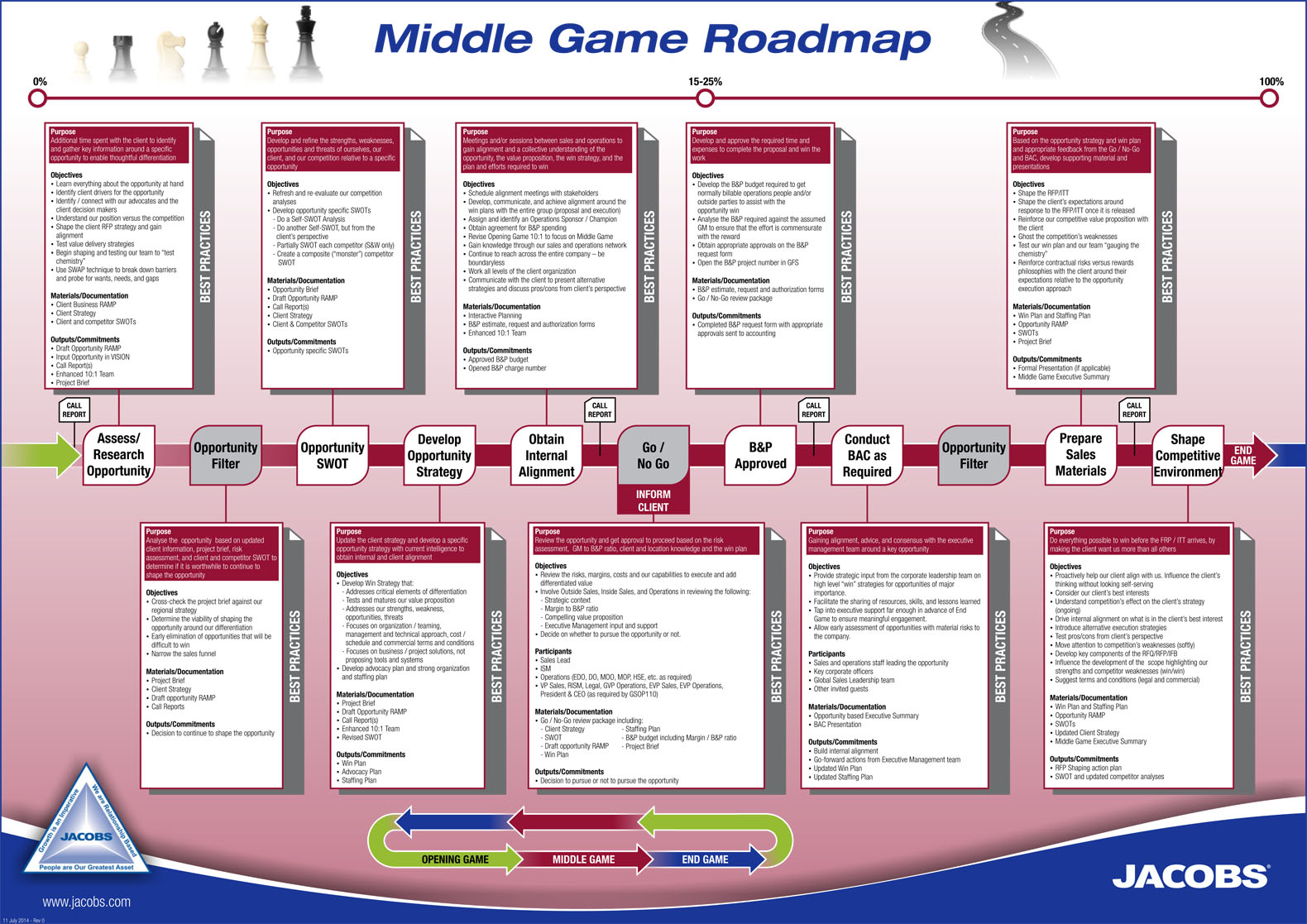
The company separates the early stages of winning work into three parts: the opening, middle and end game. To put this in context of a project timeline, the tender decision is the last part of the end game. There are some flowcharts to guide people through this process (see below – handy for new people like me). The middle game decides the go/no go in pursuing the work from the client. Prior to this a SWOT analysis will have been completed on the Jacobs bid, but also one that looks at the competition.

There is a surprising burden of paperwork that has to be produced during this evaluation process. I can’t help thinking this is a lot simpler in a smaller consultancy – is anyone able to comment? Is it equally paperwork heavy in the likes of Arup?
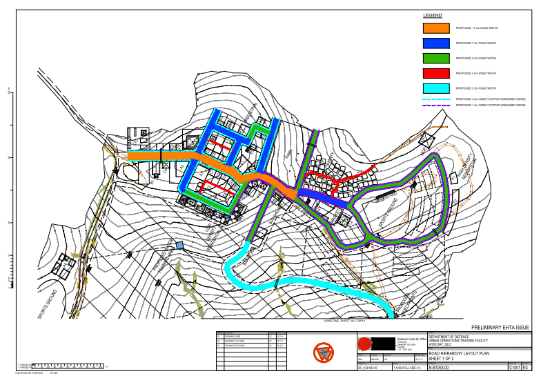
Most of what I’ve been doing so far is related to the early stages of bids and tenders, or so I thought (but these are in the middle and end game of the Jacobs initial process). There are 2 defence related bids of one and one health centre. The defence work if for the construction of an Urban Operations Training Facility (UOTF) and another Explosive Hazards Training Area (EHTA). Both are small in value and they are both located down near Sydney. This week the decision was made to “no go” the Holesworthy training area on the grounds that it wouldn’t have been profitable without winning the larger bid for Wide Bay. Too much risk I guess. The concept for the Wide Bay training area is shown below. The different colours denominate road types and widths.
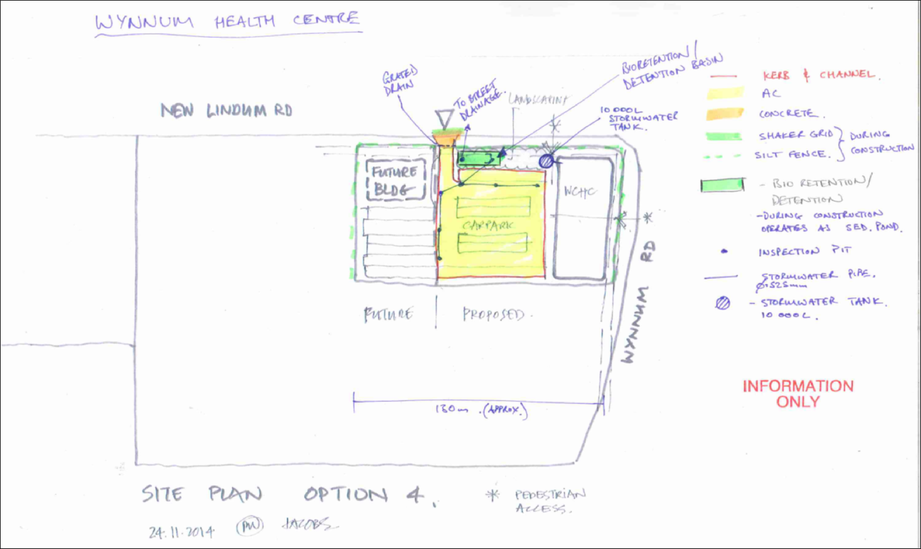
I’ve been focussing on the Health centre this week and getting together information to allow the contractor to complete the pricing for his bid. I’m probably starting to go a little further than I should at this stage, but I have the time to do this before the other projects kick off. I’m also compiling the cost and margin tracker for the civils team that will work on it. This will allow me to put forward the fee for the civil works. There is also a list of assumptions, inclusions and exclusions to submit (even though it is very early in the design process). See below for my first iteration marked up on the architects concept. This has progressed a little, but should give an idea of what I’m doing.
Its safe to say I’m getting some good experience logged towards B1 and C5 in the spec. Depending on the outcome of the bids there should be a number of workshops with the client and the other teams to work on value engineering. I’m also sticking my beak into the contract arrangements and I’ll be pestering the legal team in the new year. I’ll look to expand on what happens after the “end game” in my next blog.
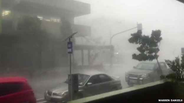
It was a bit stormy over here last week. It made the cycle home a bit interesting.
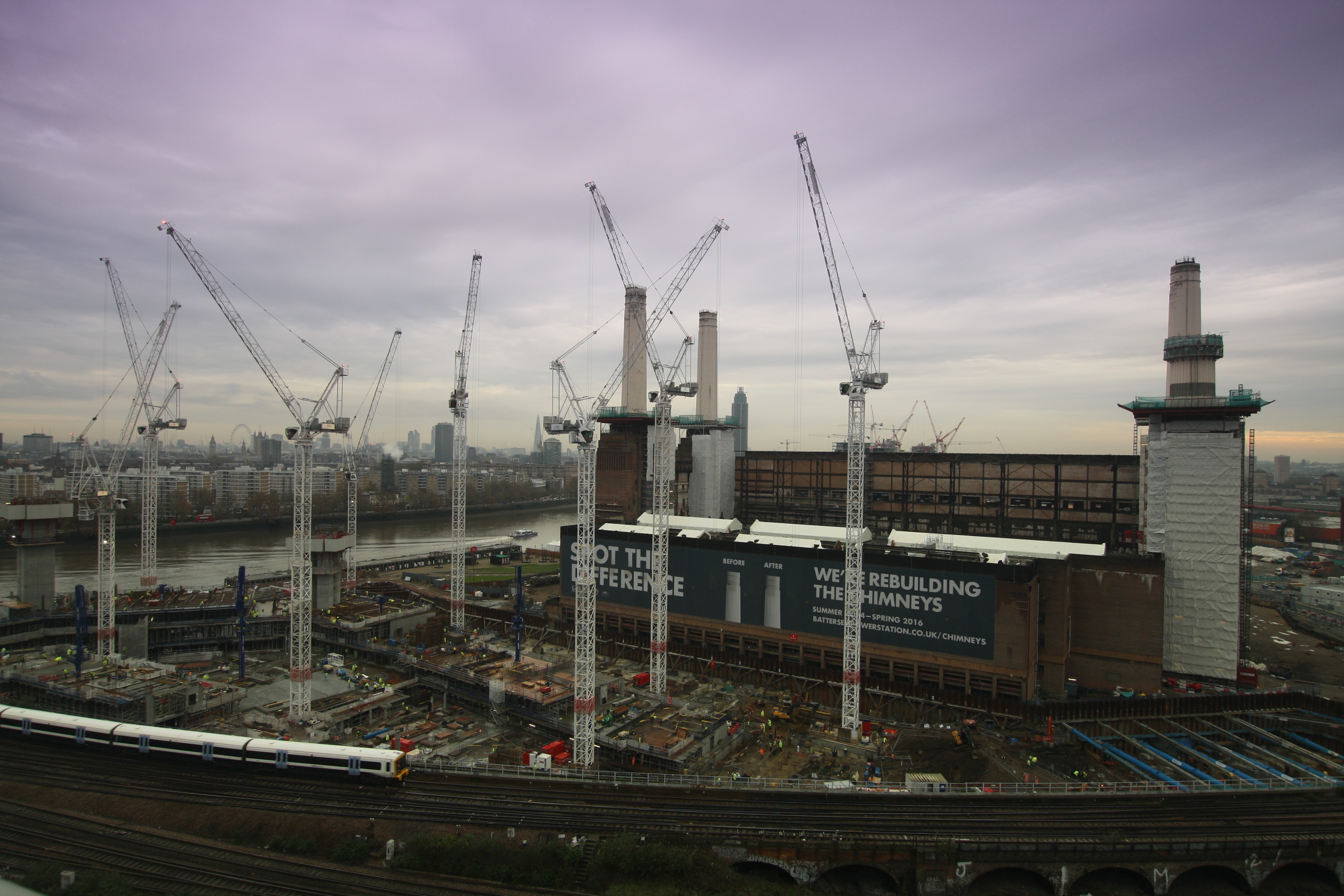
End Ex at Battersea
End Ex was called for me at Battersea on Friday and as I handed in my phone and PPE I realised that I had outlived the Project Director, Construction Manager, Construction Project Manager and the other Sub-structure Engineer! There were only 2 others in the original construction team that had lasted longer than I had!! To me that suggests that the grass is not much greener on the other side and that this project was certainly taking it’s toll on the workforce. My task back in Feb was to complete the installation of the utilities and Network Rail Road by the 26 Apr. Here is what actually happened and why:
-High Voltage Cables (power on planned 1 Apr): Actual power on: mid-Oct due to client not completing the contracts with the shipper and meter operator.
-Potable Water: Pipework installed on site, still awaiting pressure testing, swabbing and chlorination which can’t be achieved until just before the final connection to Thames Water-they still haven’t got the pipe over Battersea Park Road yet.
-Comms: Ducts installed but BT are yet to bring their infrastructure to the site boundary.
-Gas: Not even designed properly yet!
-Foul drainage: See microboring.
-Surface water drainage: No pumps installed yet as they haven’t been ordered, outfall to the Thames has been redesigned to accommodate Northern Line extension works and a new flood defence consent is required.
-Network Rail Road: Part opened on 26 Apr but remainder not opened till 30 Jun due to the requirement to install a second retaining wall. The road was then not wide enough and has already been dug up a number of times to pull temporary HV cables and find water hydrants.
-Road Retaining Wall: Completed on time but part was broken out by the concrete frame sub-contractor for access to arches.
-Microboring: Much to my amusement the microboring machine was still sat outside the launch shaft on Friday afternoon when it was meant to be halfway under the road by then. On digging the reception shaft they found that the sewer was actually 1.5m closer to the bridge than they thought, leaving about 0.25m to get the 1.75m machine out of the ground! I refrained from shouting ‘I told you so, should have gone with pipe-jacking!’
So in terms of grand achievements part of me feels that I have failed but they have all been as a result of the large complex moving parts of the project or client and third party involvement. The only thing I would do differently is be stricter with monitoring the Quality Assurance of the sub-contractor as they got away producing extremely bad ‘as built’ records and some mistakes were made with connecting ducting. Until the project employed a Quality Manager we were making it up as we went along! On a positive note I have learnt a huge amount on the project especially from a contract management, quality assurance and health and safety point of view. Now I need to just turn my DO’s into ICE speak to prove that I have been achieving everything.
Here’s a start and finish picture of the project showing that we have actually achieved a hell of a lot on an extremely complex site with many constraints. I think Rich G will have an interesting time there and enjoy being part of such an iconic project. They can certainly do with some military help in terms of planning and co-ordination!
Feb 2014-a muddy puddle!

Nov 2014-Upwards progress in the north and excavation almost complete in the south.
Bahrain Infra
All – some pictures from Bahrain on my page – interior works, exterior works, blockwork and roof installation for anyone interested!
http://www.roselliott.wordpress.com
Keep going everyone and best wishes,
Ros
Capts Blog – A final word
Has nine months really passed, time on attachment has gone very quickly. As I leave Liverpool Street here is a quick update on my areas of responsibility.
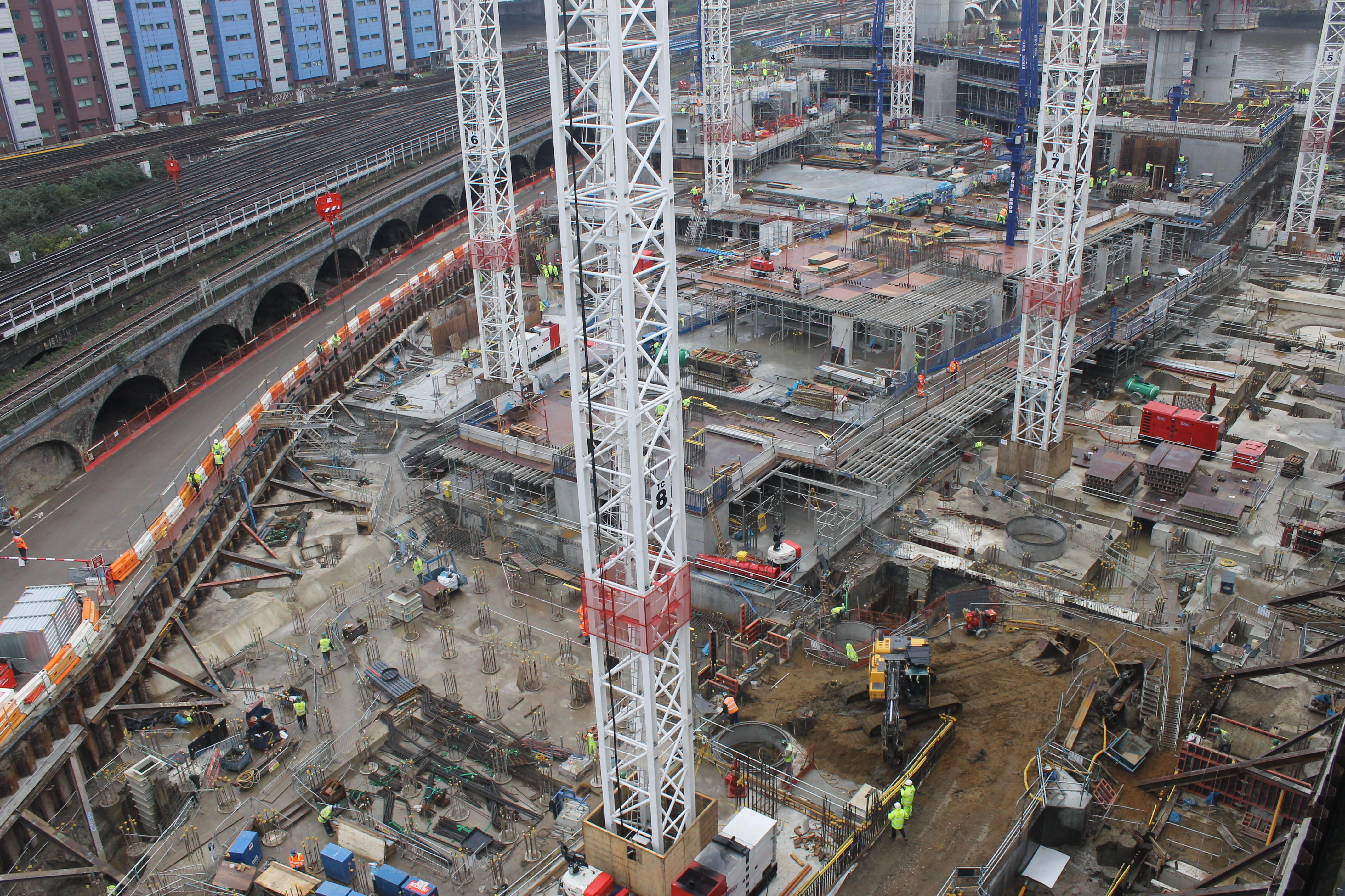
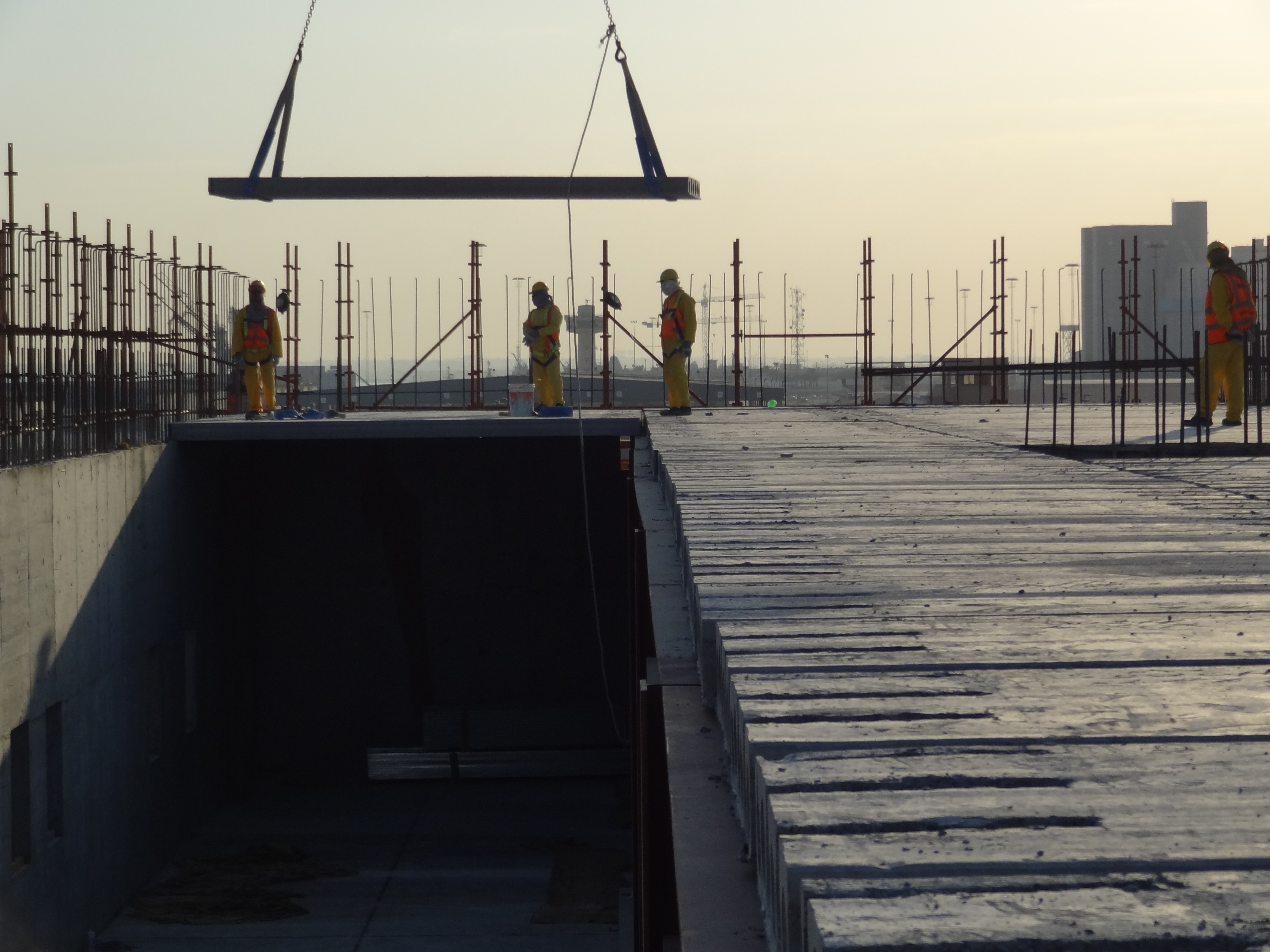
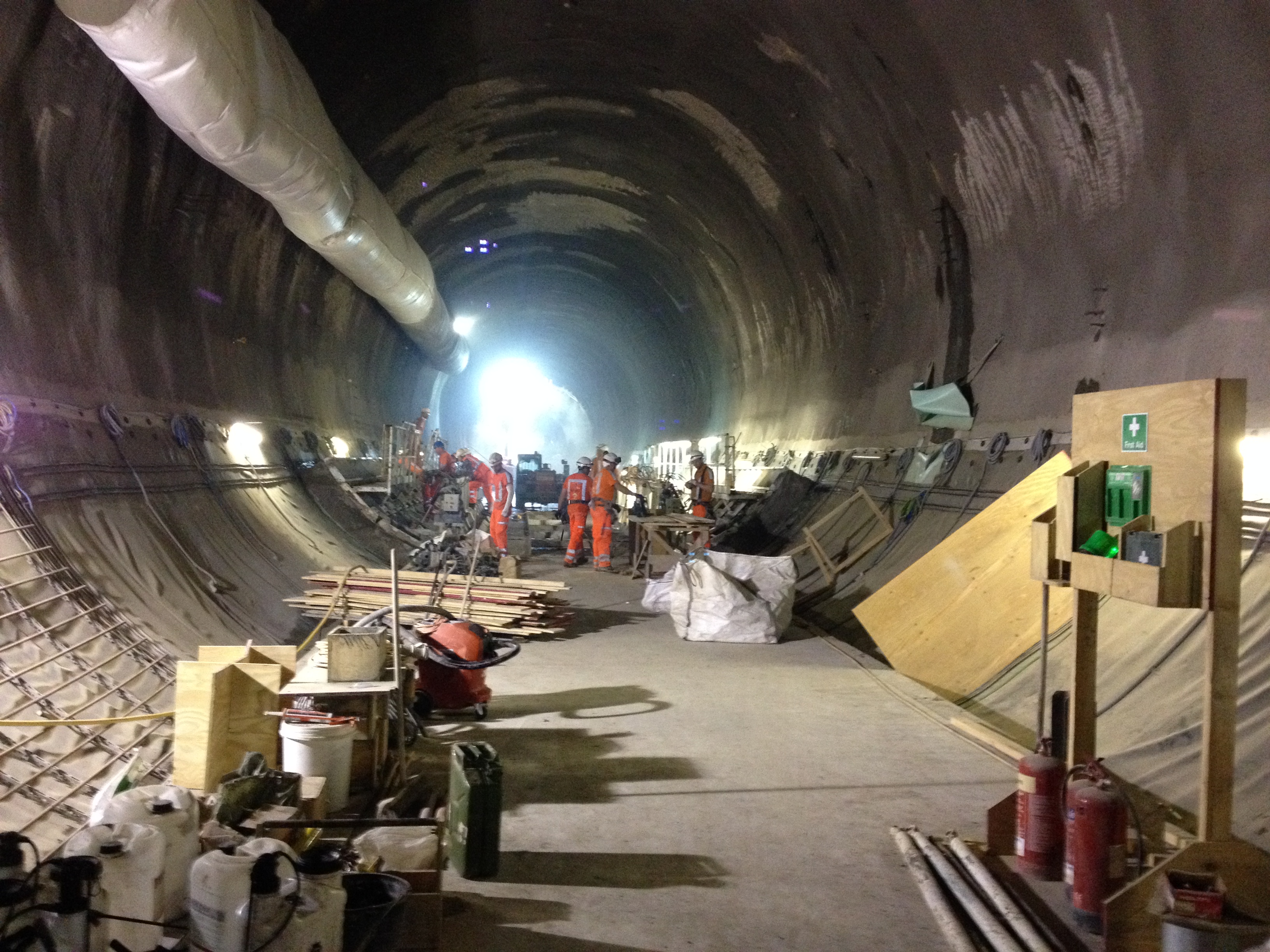
Site in General. At the time of my departure we had just completed the concrete pour for the penultimate slab at 78SSL and works had commenced on the excavation to the final level 73 SSL. All in all some 2,400m3 of concrete poured and nearly 2000 tons of steel fixed in the preceding slabs. The final excavation would prove the most complex as a the break out of the pile wall to create the access tunnels to the platform would need completed. During the breakout of the pile wall a temporary section of slab would be required carry loads across the sections of pile wall. I have intentions to return to the site to witness the pile wall breakout as the plan is to use a steel and diamond rope in a winch to cut the piles like a cheese wire……I would like to see that as the piles are 1200diameter with heavy steel reinforcement, but I have been told it is possible.
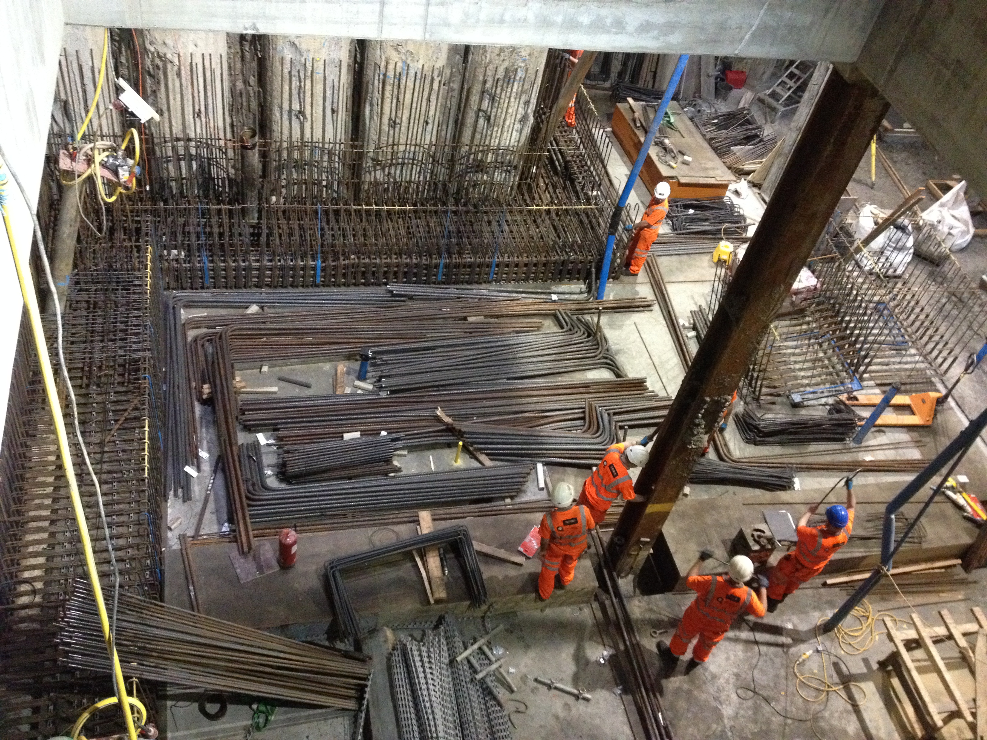
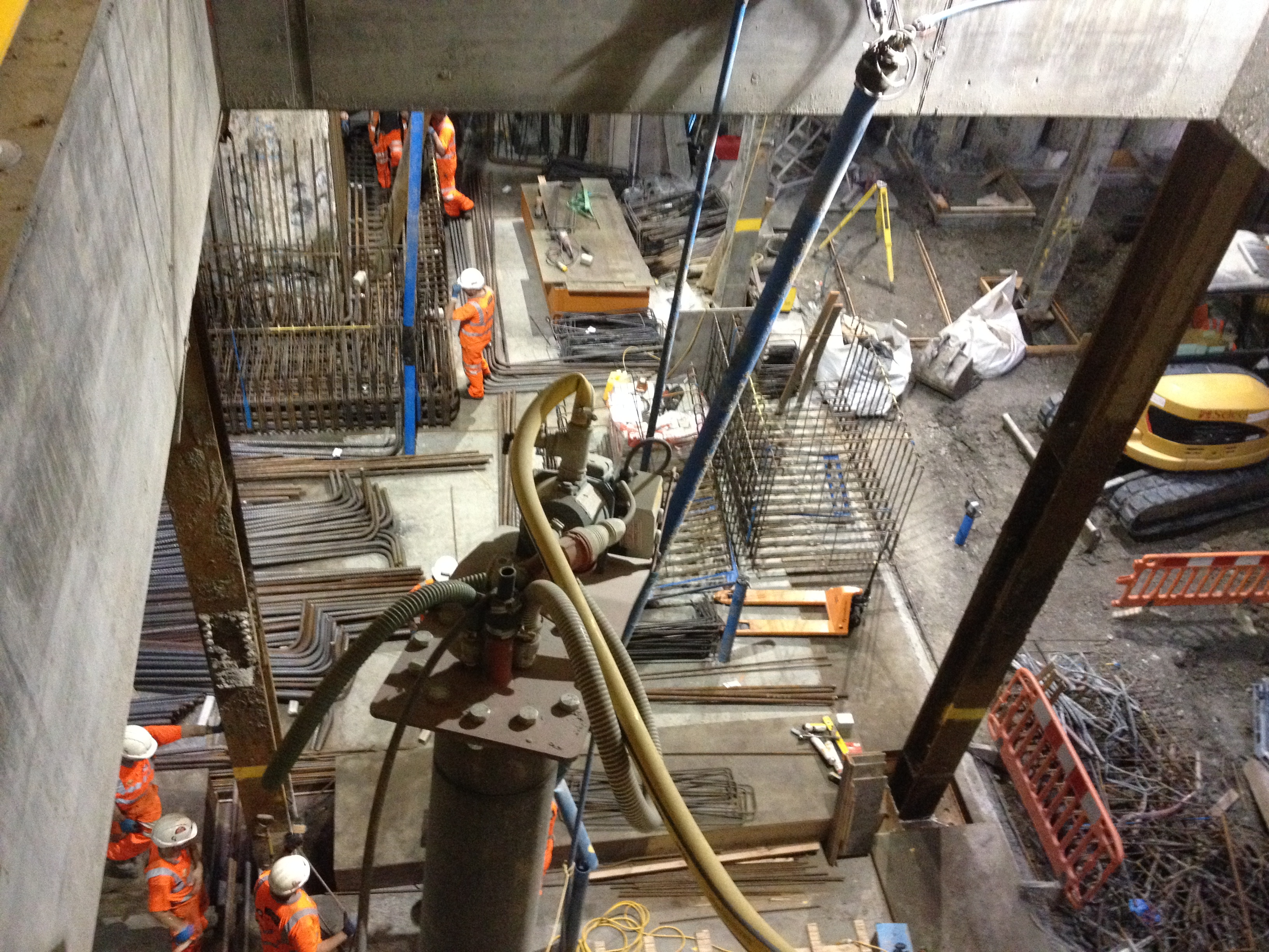
Installing steel at the penuletimate slab level & view of the running tunnels adjacent to site
Depressurisations wells. My part completed wells installed, working and a steady decline of the pore pressure had allowed the cessation of works to be lifted and the excavation to continue. Having now entered the Lambeth Groups of soils and with the wells firmly in the course grain gravelly layers the amount of water being pumped had dramatically increased from 200-300litres per day to20,000 per day. All was going well up until my last day when we arrived at work to discover the site flooded from an over flowing settlement tank, the cause turned out to be that the contract excavating the tunnels adjacent to our site had turned their dewatering system off on the Monday and it had taken a week for the recharge of the ground water to reach our site. Although the wells we had installed were capable of pumping the increased amount of water we did not have sufficient storage capacity. It also turned out that the young apprentice responsible for monitoring the flow rate had neglected to do this and so the increase in water flow had not been picked up.
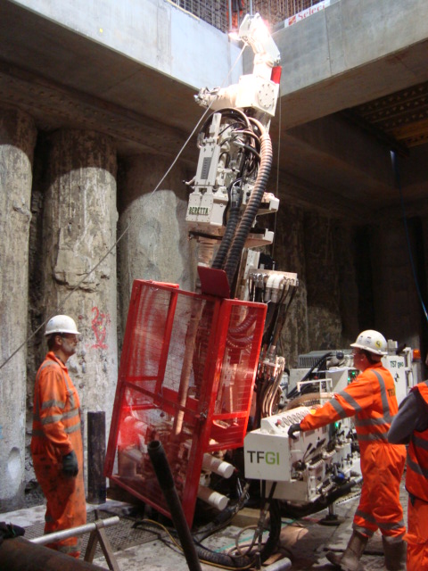
Installing the depressurisation wells & the well head of the vacuum edjector depresssurissation system
Precast Concrete. Leading the charge for Laing O’Rourke I had at the time of leaving managed to secure my greatest legacy to the Liverpool Street site, the use of precast concrete sections to complete the Northern Wall of Blomfield box. Through the use of negotiation skills, professional engineering judgment, coercion and by being a deviousness and sneaky bustard I coordinated efforts and produced the Value Engineering proposal that convinced Crossrail Engineers that the use of Precast Concrete was in fact the best option in terms of engineering risk, H&S and commercial risk.
The complicating factor in the design of the precast concrete sections was Crossrails insistence that as they would be required to take structural design responsibility then they would design the wall sections and inter wall connections. As the wall is to be next to live LU track and undercover the wall must have little to no maintenance burden and cannot use any materials that release toxic fumes when burnt. As a result Crossrail had designed the walls connections as an insitu concrete stitch creating two problems for us as the contractor to overcome; Firstly this insitu stich requires the reinforcement within the wall to be tied to the structural frame of the building and then concrete poured between the steel to join the wall and structural frame together to form what engineers have described as a monolithic structure. Secondly how do we turn and ten support the wall sections during construction. The walls have a long slender overhanging nose section that cannot be used to support the wall during fixing and pouring. With the temporary works team we had developed a rough scheme of manoeuvre using Perri Strong backs to create legs to support the wall. These legs then had to be offset from the wall sections to allow the site operatives access to fix steel and pour concrete. As a result at my time of departure I was working with the temporary works team to model the loads on the connections. At the time of departure we were on the 6th iteration of concept designs from the design consultants Motts….
I have now moved to Arup, London office without a speck of mud insight. I am now surrounded by a mix intellectual geeks and glamorous Europeans. I have discovered the free lunches that accompany the lunch time CPD sessions and have attended two this week already. The festive season has already started with a wear your s***test shirt to work day and festive if not geeky pub quizzes…John I am sorry to disappoint but my team came last at the geotechnical Christmas quiz…….
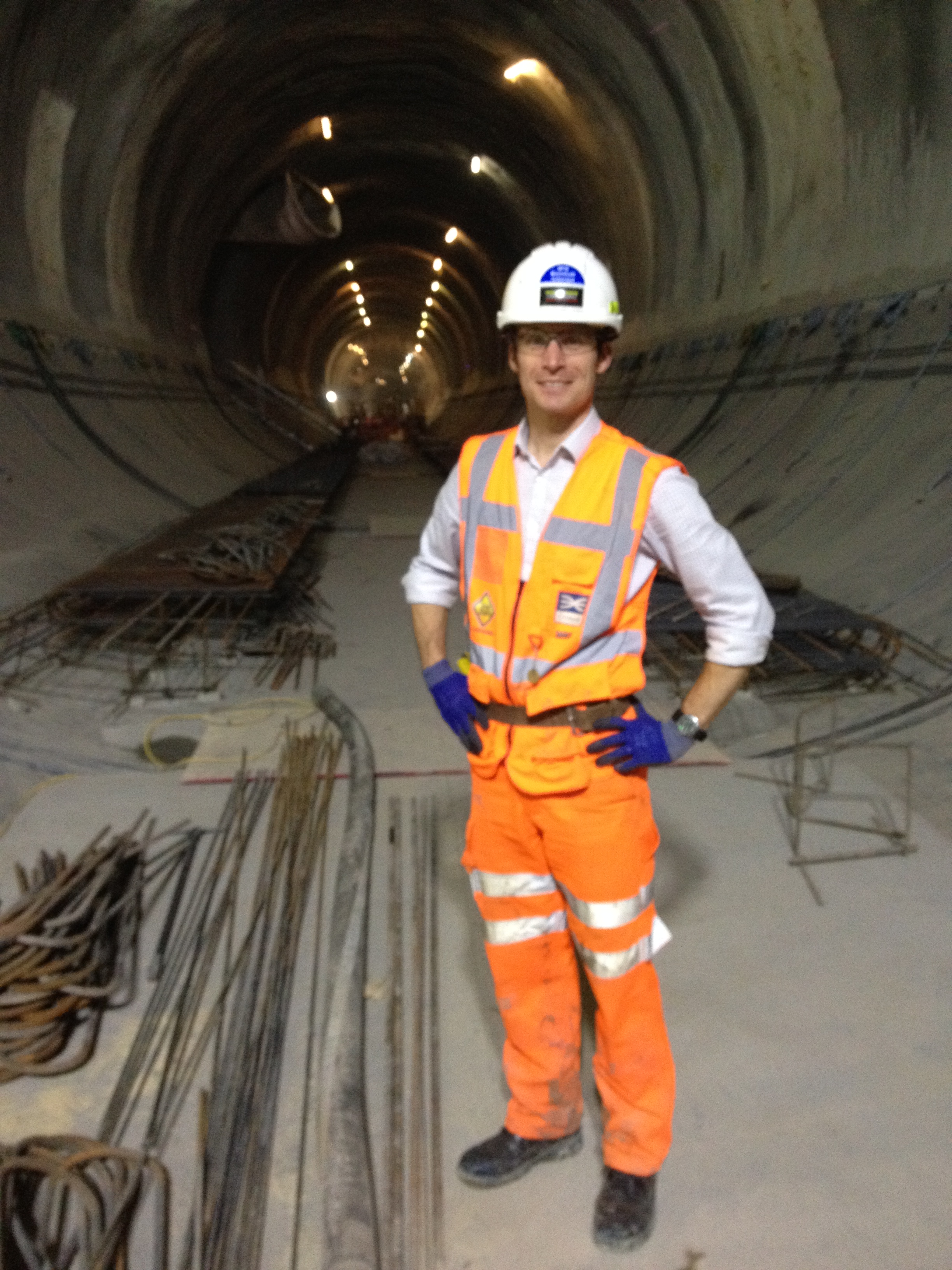
My final walk in the tunnels and on site
Phase 1 and chartership
The documents I refer to below are mainly (not exclusively) for those following the IMechE route. However, I believe that it is worth all PET students considering the end state. Personally, I failed to spend enough time in Phase 1 considering it, i.e. chartership.
I would commend to you all that it is worth investing some time in digging out the UK Standard for Professional Engineering Competence. Having put your hands on that document then read it and spend time understanding what the statements really mean, as they are in my opinion rather vague. Whilst you are at PEW you are in a good place to speak with you mentor and ensure that as you head out to industry you get immediately after those tasks that provide evidence for competence and where appropriate reject opportunities that don’t provide evidence or decent personal development.
There are a few documents out there that are easy to find if you know to look for them (www.imeche.org):
– UK Standard for Professional Engineering Competence. (http://www.engc.org.uk/ukspec.aspx)
– Competence profiles – Guidance for applicants and assessors. Part 2 industry classification (K) – The Army.
– IEng and CEng guidance notes.
– Guidance on the Preparation of an MPDS Final Personal Report and Development Action Plan.
As a closing remark, I recognise that Phase 1 has its own pressures and putting this off appears an acceptable COA. However, if you do decide to follow this advice it will save you hours of time working out what the EC is looking for and may prevent you being burdended with a task during Phase 2 /3 that adds no value, except to the company that is sponsoring your attachement.
Installation of the six mega embedments at the South Bank
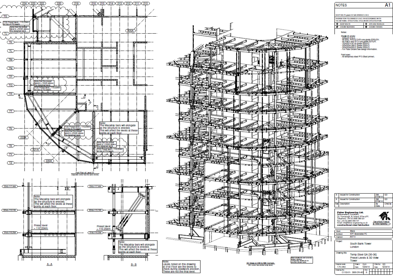
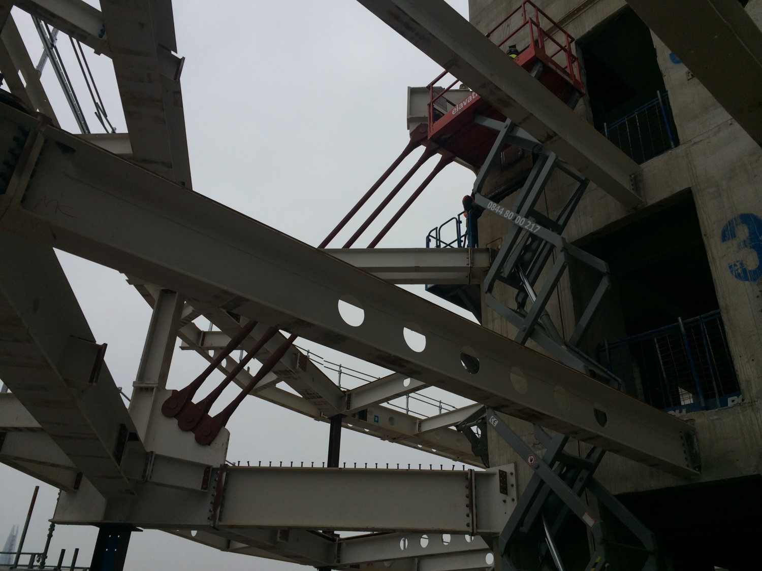
 In an early blog I described how the load path of the new steelwork on the tower extension is pulled up and into the core through Macalloy bars.

This is required since the existing pre cast columns crank inwards towards the bottom of the building, inducing a large moment that cannot be dealt with.
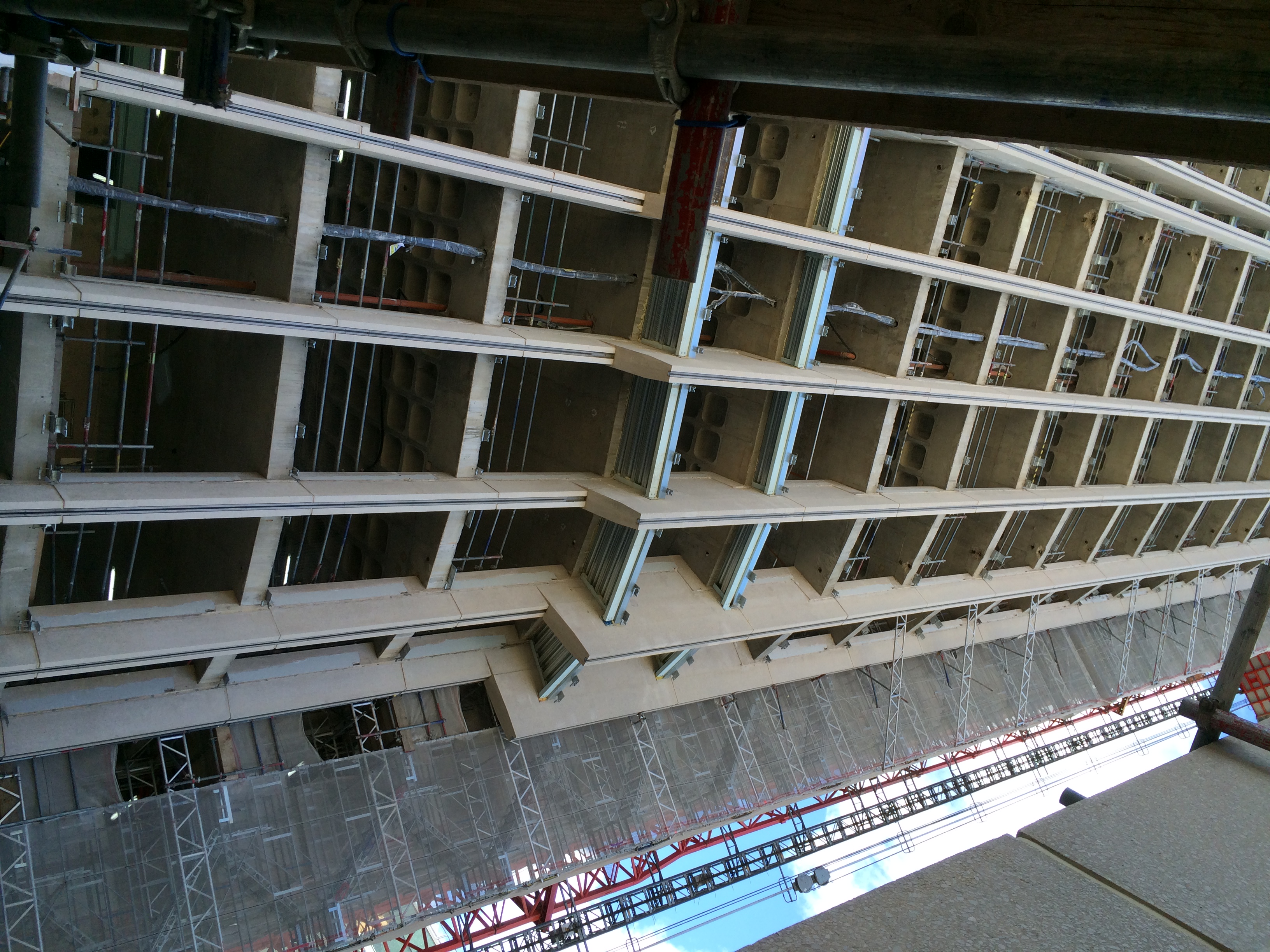
The existing column crank can be mid picture
In the temporary construction condition, whilst the diagonal Macalloys are not employed (because we were building them) the weight of the steelwork is propped off level 30.
This load passes down the existing pre-cast perimeter columns and into the foundation.
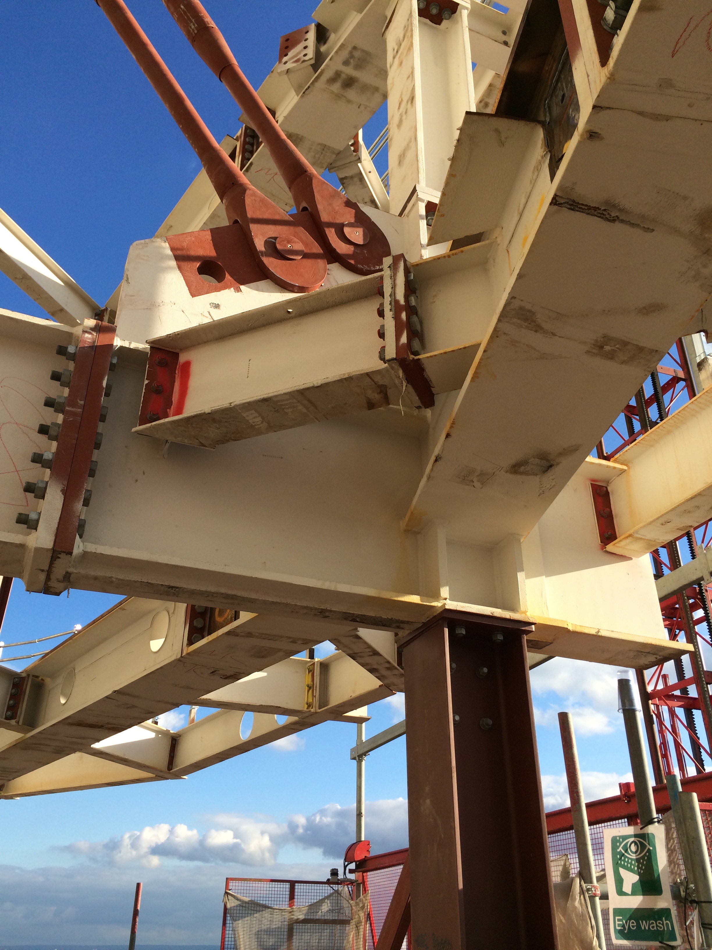
The red steel is the temporary steelwork sat on the top of the existing columns
I undertook analysis of the existing structure to determine how much steel we could erect before we reached the limit of the crank. I can report that my calculations to determine the allowable load were alright since the building is still here. Knowing the actual factor of safety during this operation was exceptionally difficult so we will never know how close we were.
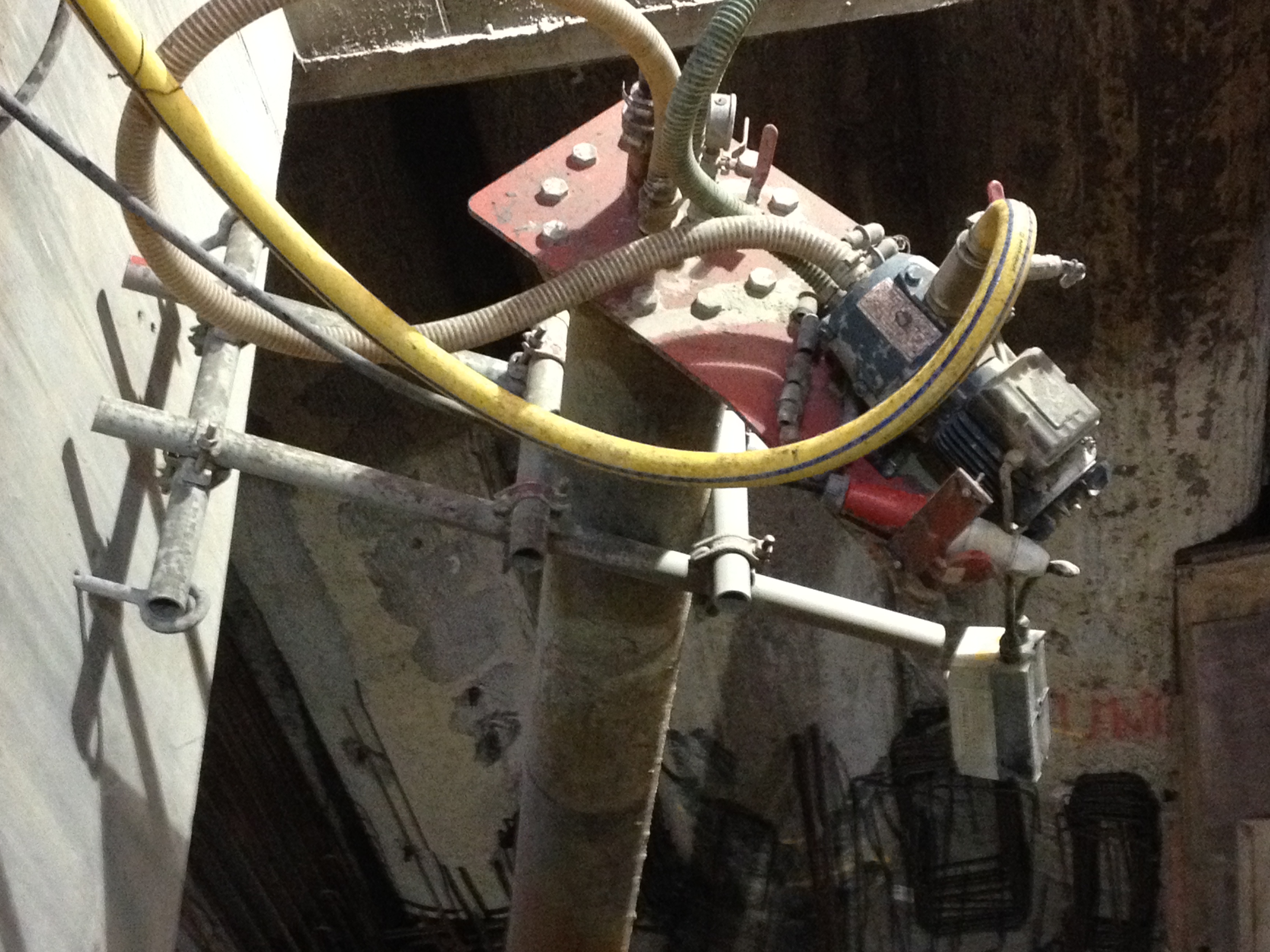
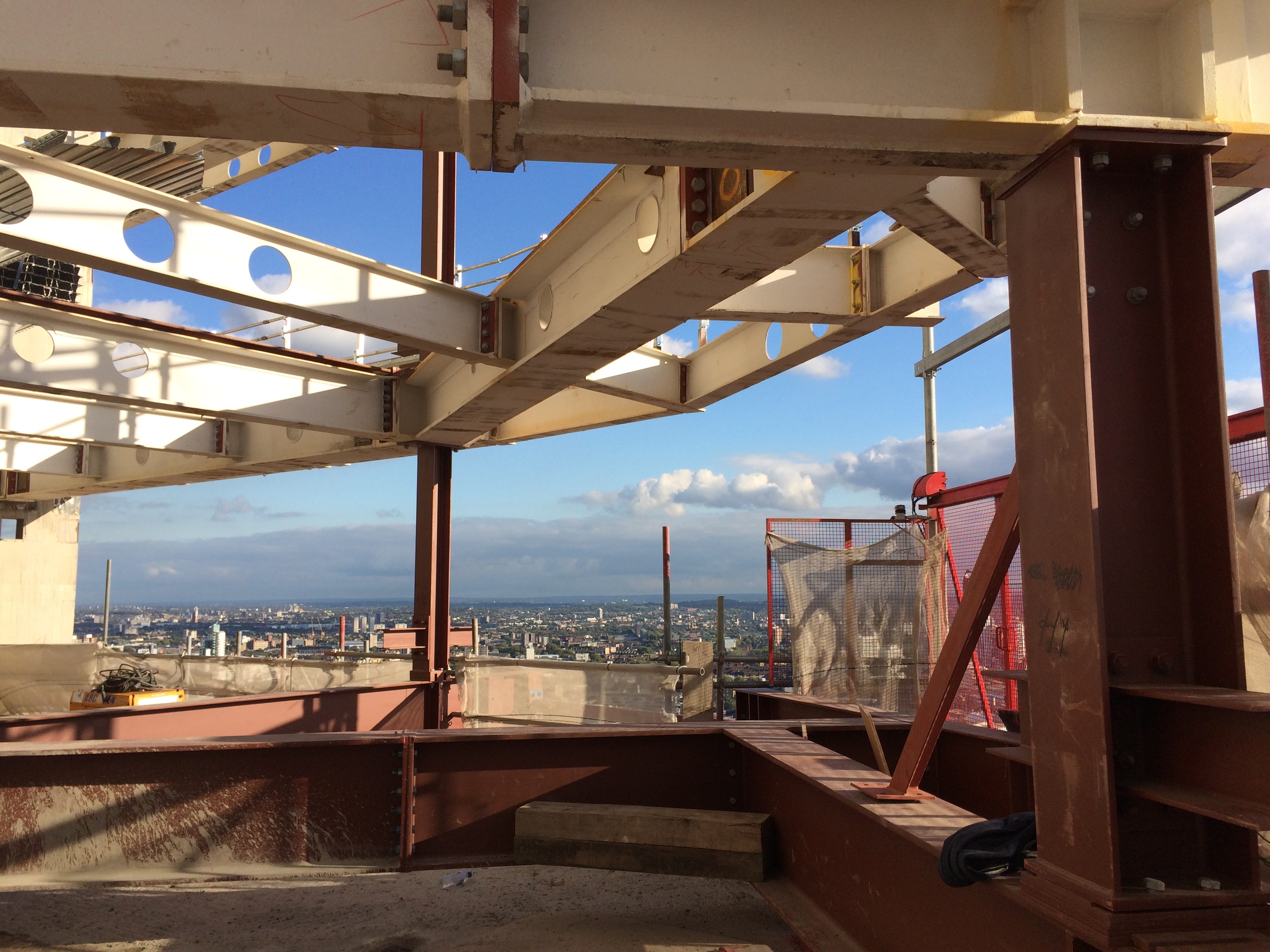
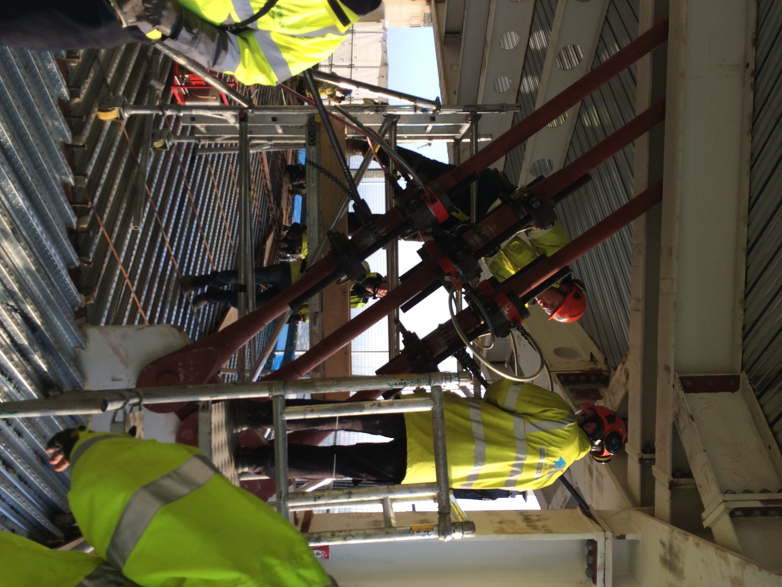
Installation of the hangers has been slow because of a number of issues.
1. PC Harringtons did not cast the correct size holes/voids in the core to allow the mega steel embedment to fit into. This required us to break out additional concrete.
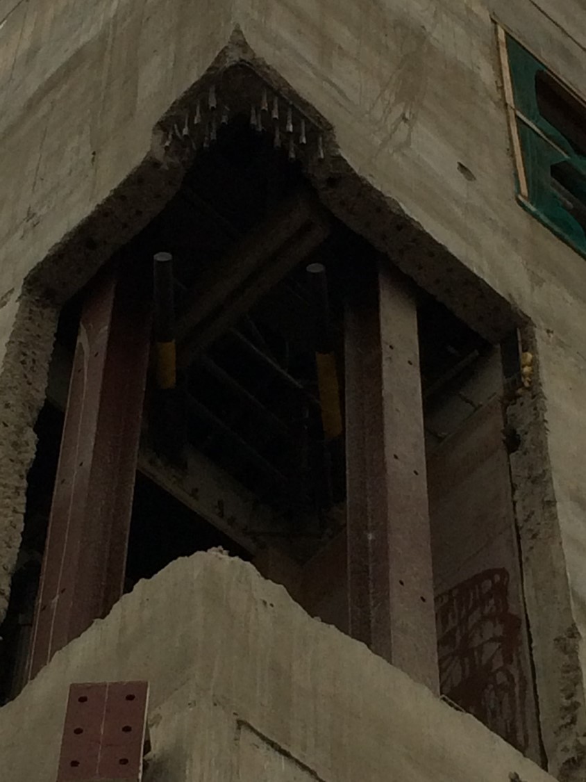
Void for the embed
2. The slipform at the top of the structure meant we could not lift the embedments into the holes until the slipform was completely removed/dismantled. This meant there was no concurrent activity

Back plate in place
3. Access to the embedments is difficult. We used a combination of traditional scaffolding, proprietary platforms and scissor lifts to access the embedments.
Access to the embed
4. Since the embedment elements are critical to the structural integrity of the permanent works each segment of work has to be inspected and signed off by the structural engineer, Mace and sub-contractors prior to moving on. This took a lot of my time as well as wasting progress.
5. Our resident engineer on site is useless. Although he is supposed to be a qualified engineer, he is not willing to take any responsibility or give a direct answer to anything. At every instance he has to refer back to his office for advice.
6. We are dealing with two sub-contractors to deliver the one element. This has required almost daily meetings to ensure progress is maintained.
So what.
- I think we could have planned better for this operation (who never says this?)
- Design information was scant. Its lack of detail seems to have then impacted upon the whole operation. Since there were so many unknowns I think higher risk was accepted prior to construction than really should have.
- We should have used 3D software to map out how the reinforcement and steel interfaced. The slipform precluded particular vertical reinforcement being fixed during slipforming. This should have been picked up. We were then in a position fighting to get hold of every piece of reinforcement that was available.
- The Structural Engineer’s designer of the embedment elements should have given us a presentation of how he designed them, and why particular elements were important. This would have allowed us to make more informed decisions on site and understand risk better.
Macalloys in place
So inclusion.
Communicating how a structure or element of it is designed is key. If the contractor doesn’t ‘get it’ then there is real risk failure could occur. Sub-contractor engagement, liaison and partnership is key to ensuring that shared progress is optimised. There was little motivation for the concrete contractor to get the job done, but lots of motivation for the steelwork contractor. Modelling of complex nodes, connections and elements is worth the time, effort and expense as it ultimately reducing time, cost and improves quality on site during the installation.
Here are some other photos of the embed.
Jacking in progress

Lift off once the macalloys were tweeked
