North Sea Update
Firstly, I apologise that it has been quite some time since my last blog so instead of going into detail on any one subject I will try and write a bullet point list of the things that have been occupying my time and some points of engineering interest:
1) Financial. I technically approved an estimate for £2.5 million and some change. This was for the replacement of the high pressure discharge cooler. This covers the detailed engineering and offshore construction costs for the project and I had to go through and scrutinise each line of the 35 page estimate because there was only £1.8 million left in the budget.
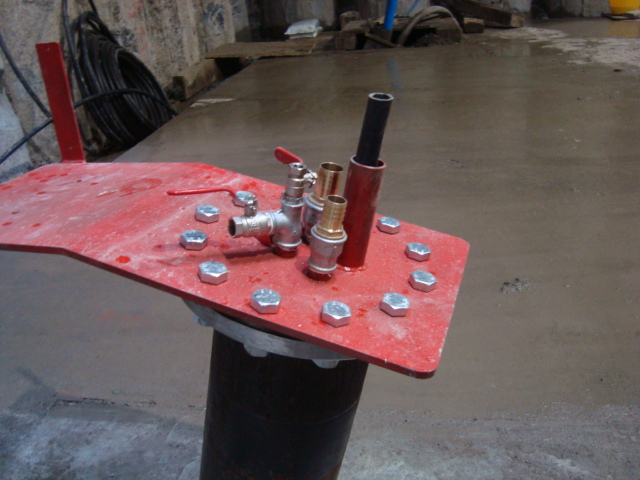
2) Flushing skid Issue One. I had to prove to the process engineer that the formula used by the vendor would work. The vendor had stated in an email the formula they had used to calculate flowrate but the process engineer was unconvinced. Although the query went back to the vendor I thought it was quicker to try and prove it myself. See the attached picture for details and hopefully I’m not wrong because the flushing has now occurred.
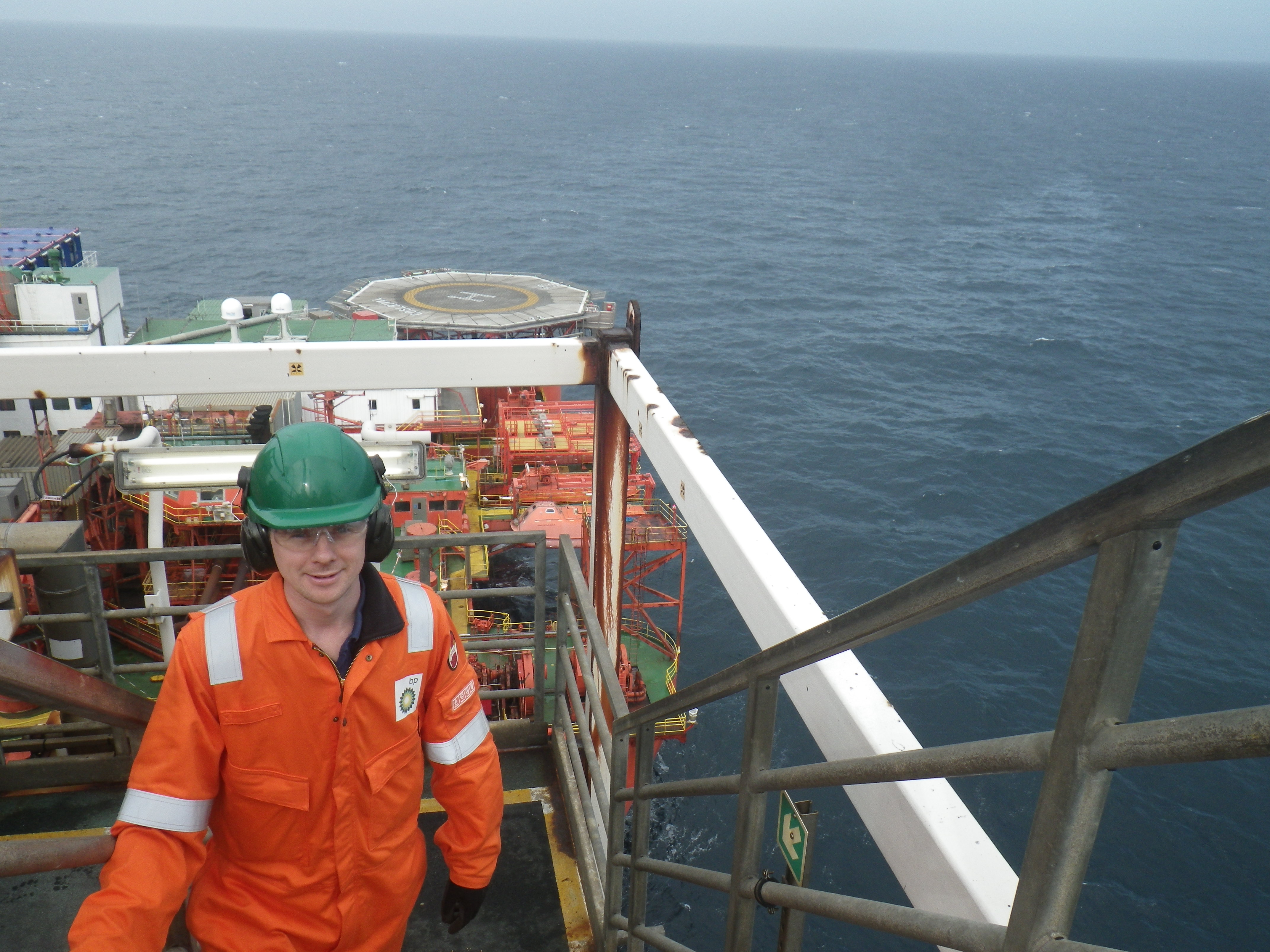
3) Offshore. I managed to get offshore again and I did some line walking, which involves trying to decipher process and instrumentation diagrams and then trying to see if what is on the diagram matches what is actually on the asset. I was also involved in an isolation for potable water prior to the issue of a permit.
4) Flushing Skid Issue Two. When there was a problem with the powering the flushing skid it was suggested that the existing hydraulic pressure unit (HPU) may be suitable to flush the system. I did a quick calculation to prove that this wasn’t possible (below):
5) Apart from that, I have been doing all the project engineer stuff for my other projects, which is keeping me busy. Hopefully, my next blog won’t take as long.
What’s wrong with this concrete?
A RC beam for a radial arm coal stacker was recently completed on site as part of a £2M variation order to the original contract. The beam effectively supports a radial arm connected to a conveyor that will distribute coal evenly onto the newly created coal yard slab.
Radial beam for coal yard stacking arm.
The stepped design allows the radial arm to move laterally and distribute the coal. The top concrete surface on the main running section of the radial beam has a series of small cracks tracing the position of the rebar and depressions inbetween as seen in the following photos.
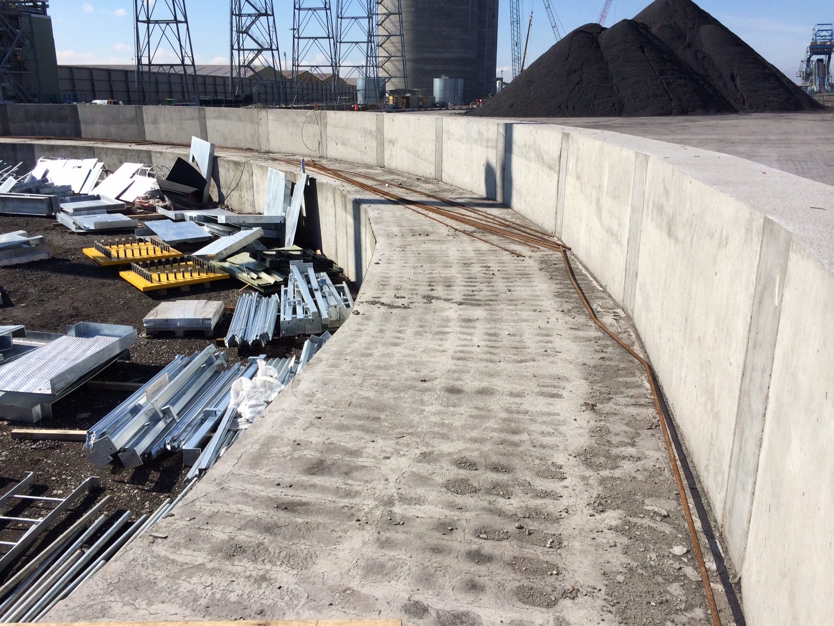
Radial beam top surface.
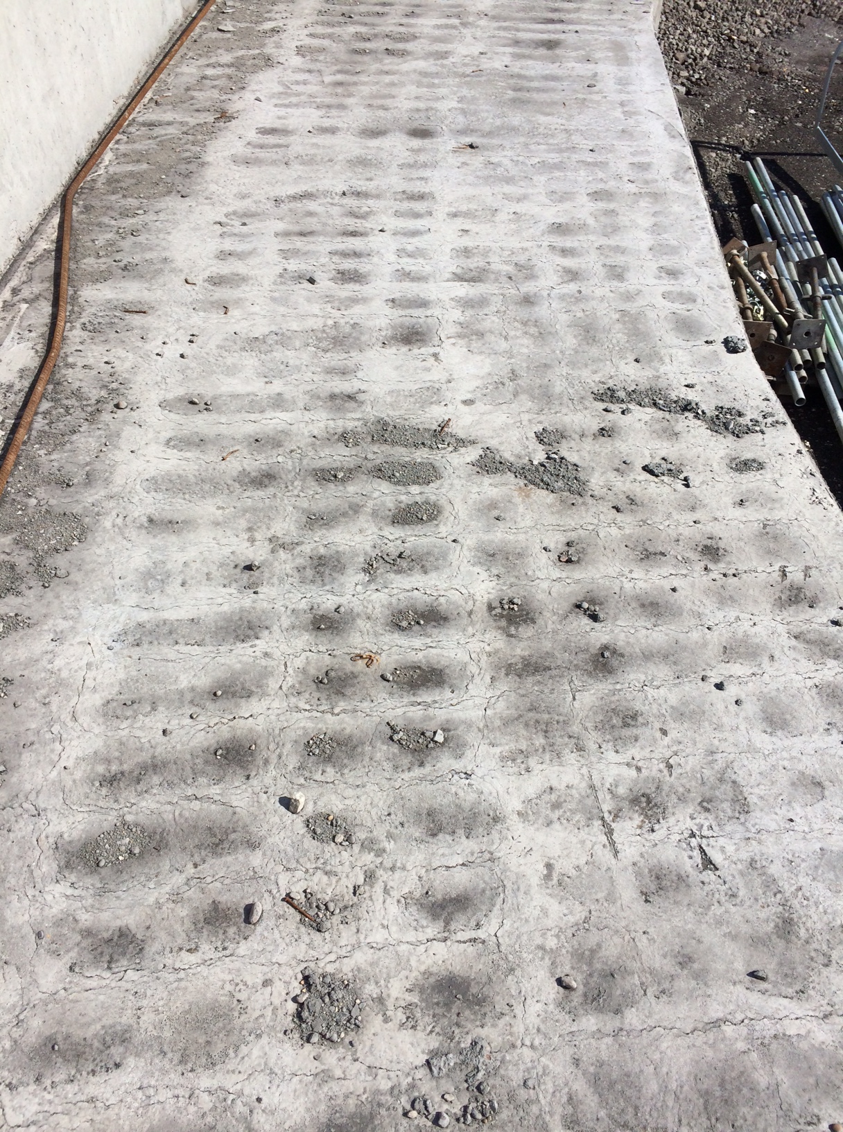
Radial beam top surface in detail.
This has occurred previously across the site (although not as severe) and seems to happen when there is a large volume of concrete poured into reasonably congested rebar.
My initial assumption was that the vertical cover was insufficient (specified 50mm) and the top reinforcement was too close to the surface of the concrete. However I saw the cover being checked prior to the pour and know that it was closer to 60mm than 50mm in most areas.
My next hypothesis was that the concrete was over vibrated creating the problem of segregation where the denser aggregates settle to the bottom while the lighter cement paste tends to move upwards allowing the lattice pattern of the rebar to be seen. This would be further accentuated by the practice of wetting up the concrete pre-pour as I have highlighted on previous blogs.
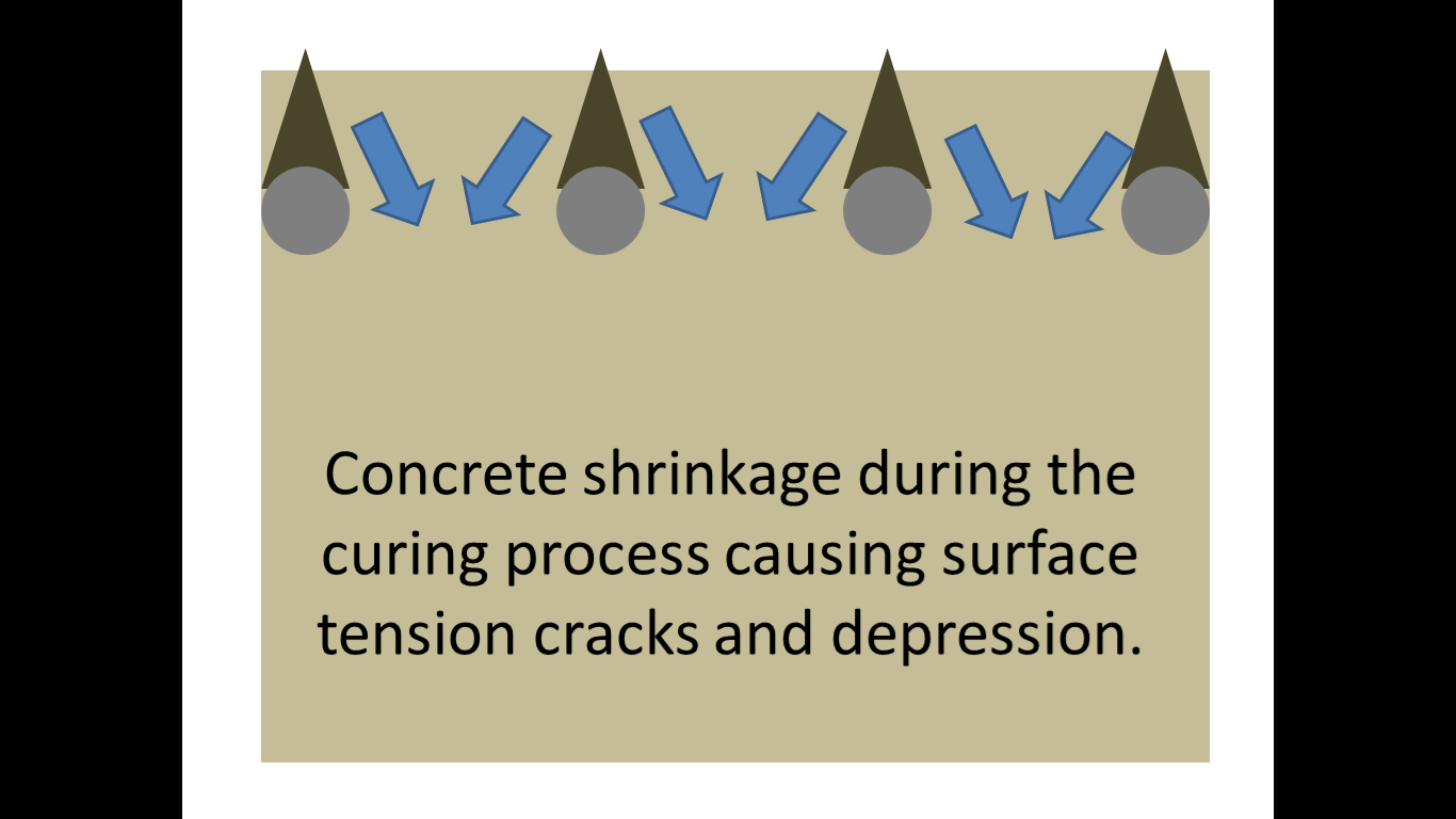
After further thought and reflection after watching the pour I had another theory and have put together a couple of slides to try and explain what I thought was happening. My theory had been that due to the depth of the pour (>2m) concrete was hardening on the top layer of reinforcing bar as it was splashed over it by the pump during the initial stages of the pour. If this was not cleared away it would create an area of hardened concrete above the top rebar that would eventually be covered during the final stages of the pour. As the concrete shrinks during the curing process it would arch over these small triangles of hardened concrete on top of the rebar, creating a surface tension and the eventual cracking and apparent depressions in-between the rebar. I know this was the case in certain areas as I spoke to the engineer in charge and he had to instructed the concreters mid pour to start cleaning off the top rebar as the pour continued due to bad practice from the sub-contractor.

Stage 1.
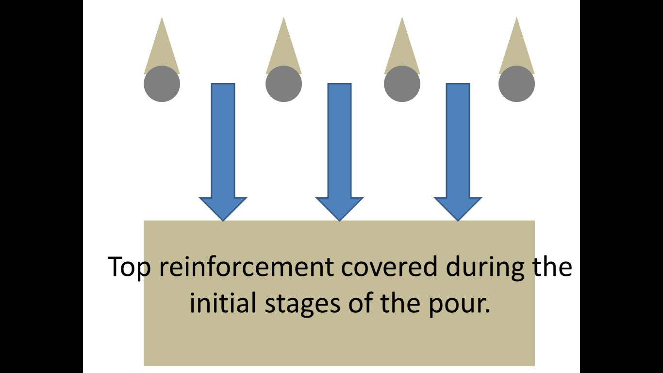
Stage 2.
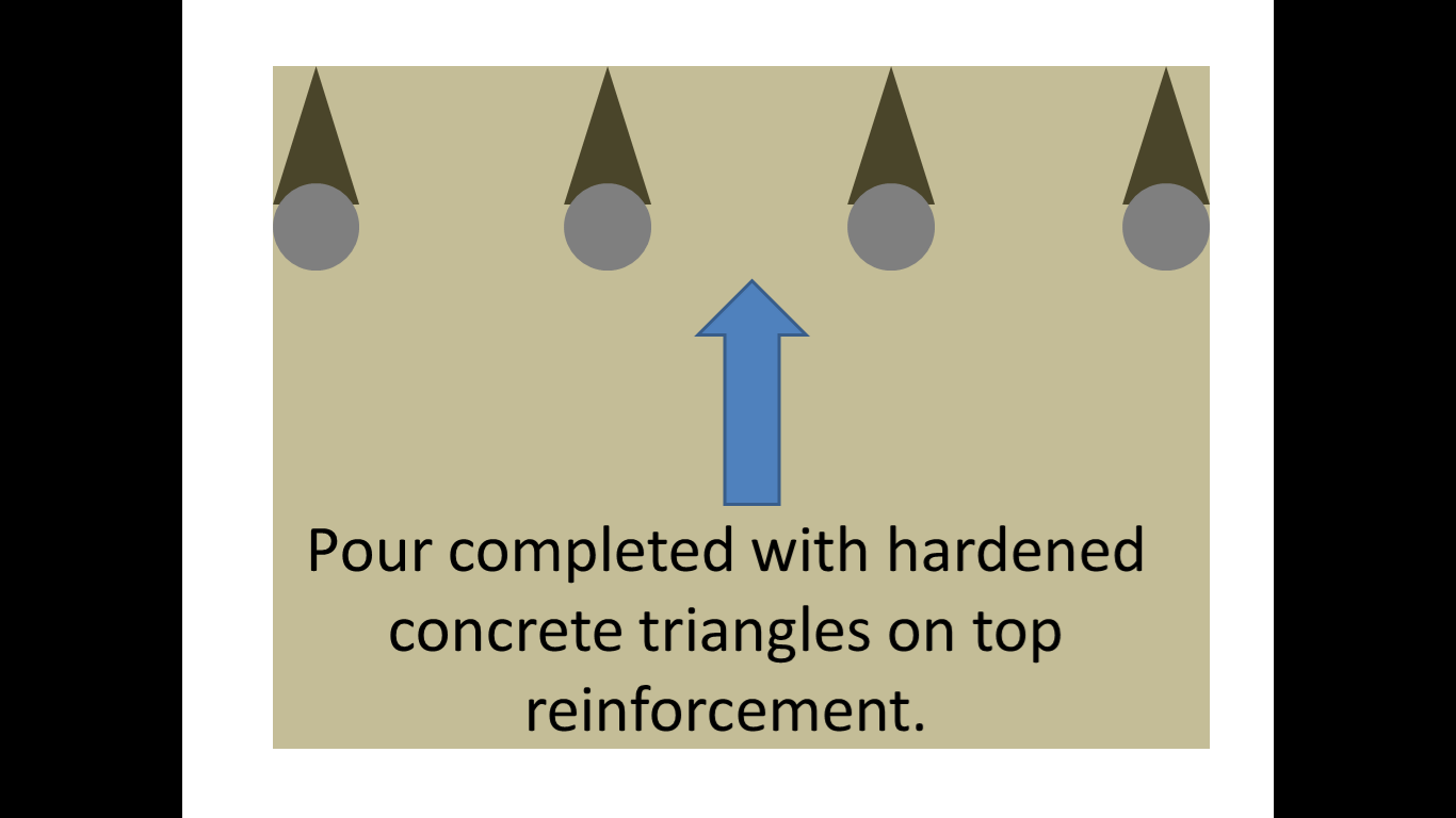
Stage 3.
Stage 4.
However I have done some more detailed research and believe that the problem may be plastic settlement cracking. I found the following diagram on the concrete society website.
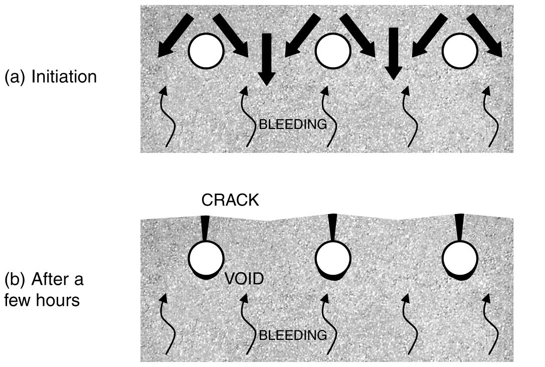
Plastic settlement cracking.
This suggests that the cracks could be caused when the settlement of fresh concrete is restrained by the reinforcement. Plastic settlement cracks can form in young concrete, within the first few hours after placing. As water moves upward through the mixture, the denser constituents move downward accentuated by any over-vibration. This downward movement may be obstructed by the top layer of reinforcement.
The plastic concrete may arch over the top of individual reinforcing bars, bringing the surface into tension. Cracks may develop at regular spacing and usually follow the line of the uppermost bars, giving a series of parallel cracks; there may also be shorter cracks at right angles over the bars running in the opposite direction as seen on the radial beam.
It is sometimes possible for plastic settlement cracks to form on a vertical face where reinforcement has restricted the free flow of concrete within the formwork. In such cases it is possible that the cracks are formed between the lines of the reinforcement.
The concrete can also be supported by the shuttering, causing restraint to the concrete in connected members. This typically happens at mushroom-heads on columns but can also occur at other locations, such as under spacer blocks. Cracks at mushroom heads of columns are generally horizontal. They are also typically 1 mm wide and can cross the full section.
So in conclusion I now believe that a combination of these factors have led to the formation of the cracks.
The radial beam was made up of large (22mm) diameter rebar along the top layer and was reasonably congested (top rebar and links at approx. 150mm spacing). The C32/40 concrete is made using 20mm aggregate and has a slump of consistence S3 100-150mm for use with the pump but is often wetted up even more prior to pouring. The concrete was pumped into place and there was no doubt that some was left on the top rebar due to splashing over it and not cleaned off. It would all be furthered by the tendency to over vibrate during the pour due to the volume.
So what’s the remedial action?
I believe the client is currently unaware of the finish as the beam has been completed well ahead of schedule. This means that remedial action can take place. It is likely that the top layer will be removed by high pressure water (hydro-blasting) down to the top layer of rebar before the surface is re-applied and finished correctly. Contractually I am unsure of where the liability currently lies, I suspect with the concrete subcontractor but I will try and dig into the subcontract to find out.
Why am I concerned?
The reason I have investigated this particular issue, that is outside of my section and responsibility, is 2-fold. Firstly it has happened on site before, including the previous sub-station ground slab and although it was not as severe when I enquired as to why it was occurring, no-one offered a solution.
Secondly, and most importantly, as I am likely to be building a significantly larger substation I do not want the same to happen to the slab I will be required to pour. Therefore any mitigation measures I can take during the pour will hopefully limit my blushes.
So what’s the preventative action?
The tendency for plastic settlement cracks to form may be reduced by adjusting the concrete mix, for example by avoiding gap-graded fine aggregate and reducing the water content, and by appropriate workmanship and control of vibration. Particular care will be required for tall elements especially the 2m+ concrete cable pits required in the sub-station base. In some cases, plastic settlement cracks can be eliminated, rather than prevented, by careful re-vibration of the concrete after they have formed. However, it is important to ensure that the concrete is not over-vibrated as may have been the case in the radial beam.
Are my conclusions correct? Thoughts???
Water, water, everywhere
It’s been a hectic couple of weeks, with several issues occurring as we excavate further but I try to remind myself that its all great experience!!
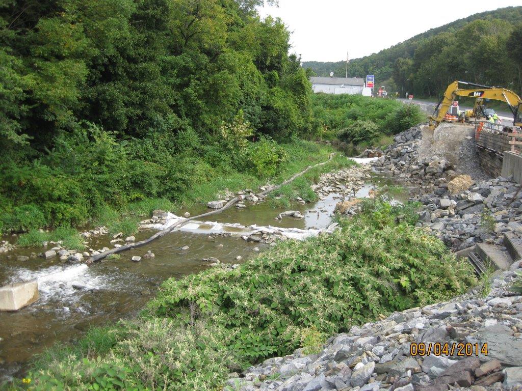
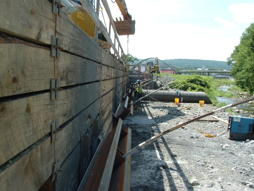
Looking north; river flowing towards the viewer. Dewatering partly in place – dammed upstream and down, with water being pumped around site.
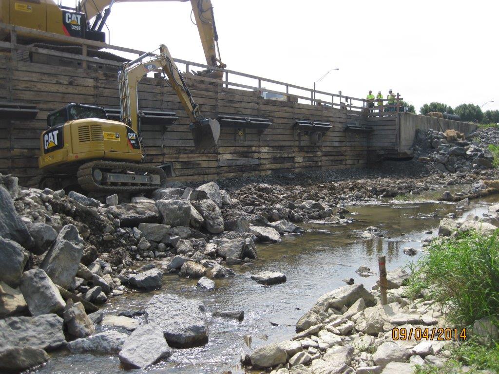
Looking at site from across the river, supposedly mostly dewatered. Note stake in foreground shows limit of excavation for the dug-toe.
As usual, pretty much everything problematic has been a result of water! Upon reaching the limit of excavation at the base of the shoring (13ft) and reviewing submittals for the structural fill I had some major concerns:
- The excavation was starting to get wet underfoot, plus I could see (in concert with some local knowledge) that the visible river at 1-2ft deep was actually running several feet deeper and was flowing under our site following its original path under the retaining wall and the highway. This tied into the issue that was raised by the tie-back drillers that they were hitting water at 15-20ft. Annoyingly the original borehole logs down to 28ft do not show any indication of water on them – not helpful!
- The dewatering was having minimal effect; there was more pumping to occur within the two dammed walls (pic top left) but it was evident that it would be nigh on impossible to dry the area in order to excavate the ‘dug-toe’, and then lay the proposed structural fill (lean clay) and compact it to 98% of lab dry density. (Readers may see the system as somewhat Heath-Robinson but we are ham-strung by the Env Agency design manual, and the inability to have any plant in the water – it was too late in the day to design a causeway and build a by-channel, plus see notes at para 1)
- As mentioned above, the submittal for the structural fill was a low-plasticity clay – the purpose was to produce an impervious layer across the site. However, if you have a look at Sheet C-303 below you will notice that the clay extends from the base of the toe all the way up to the edge of the shoring; more concerning is that the concrete wall sits on it. How on earth is a wall going to be structurally stable sitting on clay which will continually be dried out and saturated (note the mark of ‘normal water level’ – 5ft above where it is at present)???
- The damaged wall in 3 x 30ft sections had fallen at different angles. I managed to work out what was where by measuring what was poking out, and what was embedded and at what angle. The concern was the amount still embedded below the limit of excavation, and that a huge amount of sediment was entering the river downstream of the site whenever the wall was being broken up (additional evidence that the river is flowing under the site).
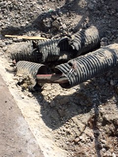
- A void was visible on the south side of the site underneath the existing wall – clearly caused by erosion once the wall had fallen. Rebar was also exposed and the water joins were ripped (see pic).
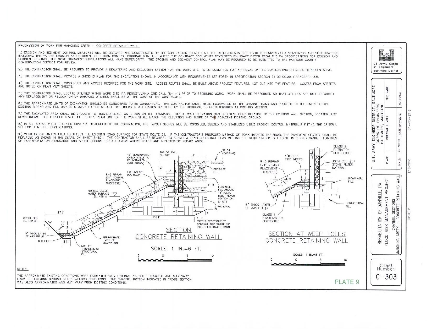
Original design
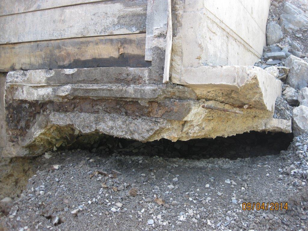
Void underneath existing wall to the south of the site
Additional limitations. Predominantly timelines…
- The Environmental Dept informed the contractor that wild trout egg stocking was to take place on 1 Oct thus the river will be in lockdown for any in-water works from 1 Oct – 23 Dec..that leaves us 3.5 weeks! Annoying that we didn’t know this as a limitation at the start (why not? I beg the question, have we got ourselves to blame?)
- The Env Dept stipulates that the dewatering scheme chosen must have a maximum lifespan of 2 weeks otherwise a new bypass system was to be designed. The contractor, without me knowing, essentially pushed himself into a corner by installing it as soon as we had approved it assuming that the E&S approval would follow shortly behind…it didn’t, it was disapproved and needed significant redesign. This put extra pressure in making any changes; some may say that is their issue/ fault – it is but we all want to get a solution in place, if we sat back, the project would fail, no funding was in place for next year and we’d be left with an open excavation, so we were all pushed into a corner somewhat!
Several conference calls later and many hours of brain-racking through options with the USACE depts of geo-tech, civil works and structures we came up with a multi-faceted solution (see pic below). The embedded original wall would be left in-situ for fear of incurring additional sedimentation, plus enabling staying on track with timelines and the consensus that it may actually help in preventing scour. The dug-toe would be removed and a new design incorporating an ‘anchor stone’ and additional reinforcing rock armour would be used (see pic), while the structural fill specification would be hastily changed from clay to a coarse gravel; this would negate the need for major dewatering and speed up time of construction. We all now have to be on the ball with processing submittals asap to meet the 1 Oct 14 hardstop. This now leaves the painful part of change orders and/or REAs but needs-must.

Slope redesign
I am pleased to say that the H&S and QC has made a dramatic turn following the insertion of the 3rd party assessor by the contractor. It is clear that morale has dived a little amongst those on site following some serious whippings, but I have no doubt they will take it on the chin and move on. It is good news, and the assessor confirmed with me that things were far from where they should be! He’ll be on site until things reach my stipulated levels per USACE specs, and then a bit longer to ensure it is maintained. He even phoned the county sheriff direct raising his concern the morning I arrived on site that some drivers were driving past at 70mph in a work zone and 35mph limit. Cue a cop-car with speed gun on site within an hour and some great viewing of law enforcement US-style in action!
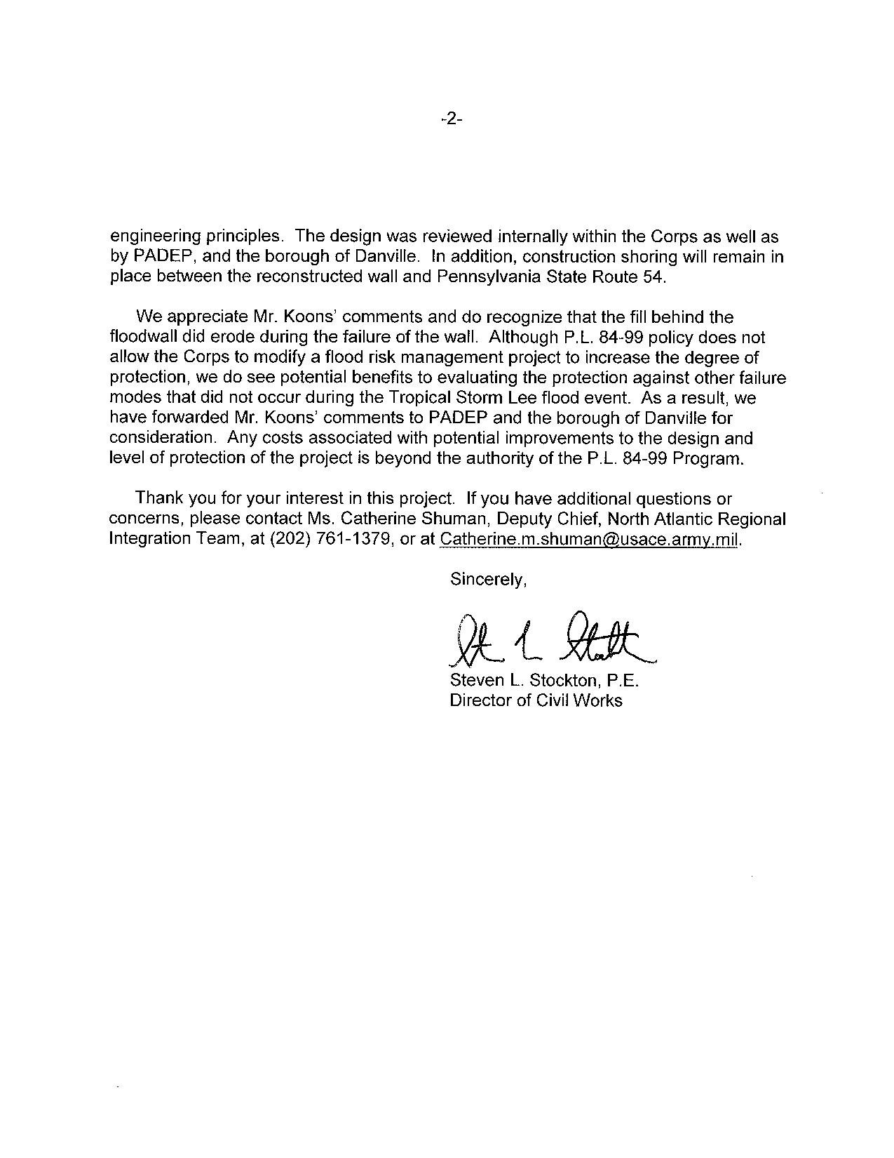
We also had a ‘congressional tasker’ (akin to the Complaints Commissioner writing directly to the CO!) …cue flapping all round. The ‘tasker’ stemmed from a Danville local writing to the Congressman on the back of a fag-packet his concerns that the project was a ‘waste of money’, because we are building the wall the same as was originally placed, and that the original wall collapsed as a result of scour to its rear. He was quite correct, but federal law (PL84) has tied our hands and dictates that disaster relief work on hydraulic related projects are done on an as-built basis. Several conference calls later, the attached letter was produced.

Plus, a bit of media publicity…
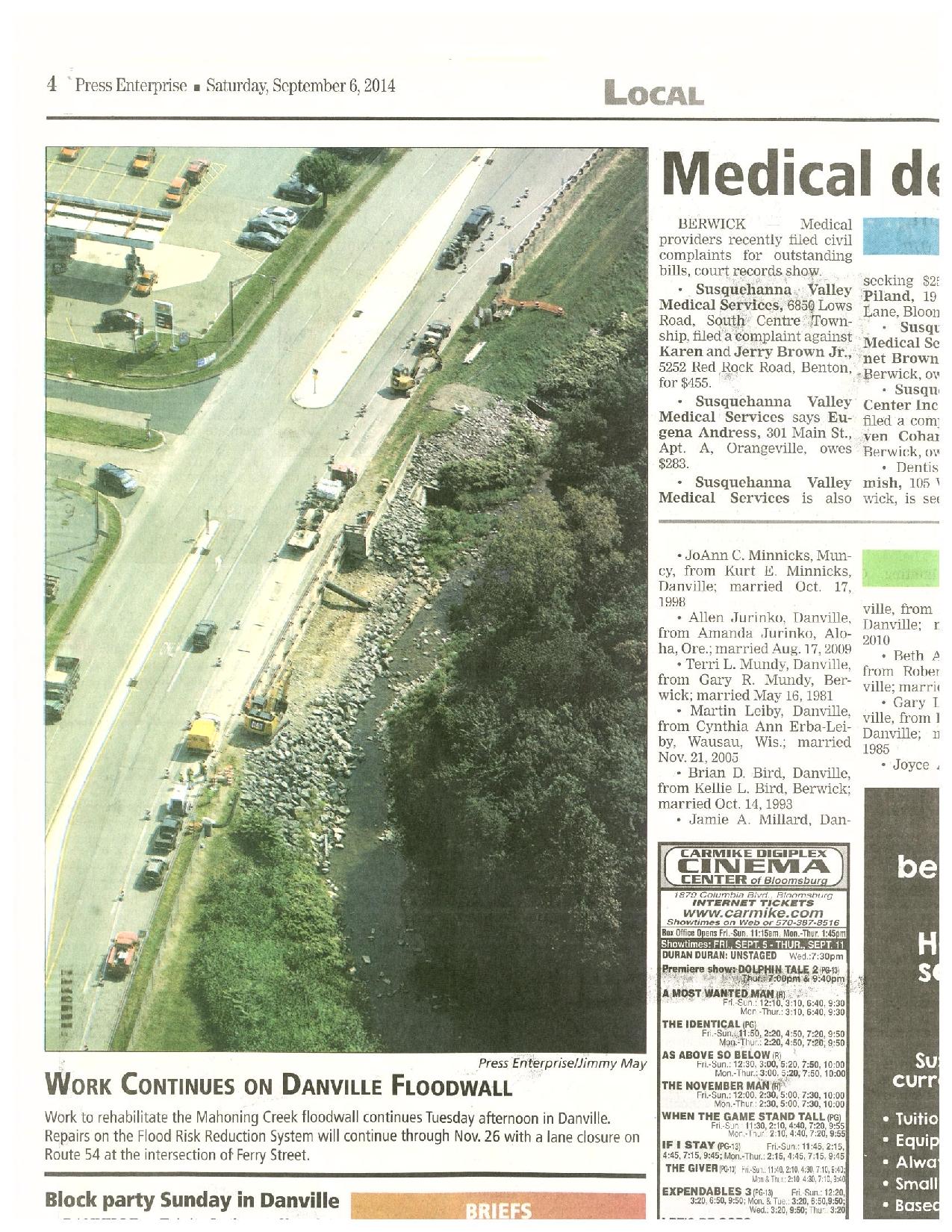
Also, this weekend sees the national ‘Star Spangled Banner’ celebration taking place in Baltimore’s inner harbour…100s of tall ships, Blue Angels flying displays etc – all to celebrate the 20oth year to the day from which the USA hangs its history…the first location to withstand bombardment from the Royal Navy, raising the stars and stripes for the first time, and providing the backdrop from which to write the national anthem! We will of course be attending…in a disguise of dodgy stars and stripes sunglasses and a Dunkin’ Doughnuts coffee permanently clasped in our hand; no-one will guess we’re British!? In other news, and not that we’re competing with the other HRH but maintaining the tradition of Phase 3, Emily is pregnant with our 3rd!
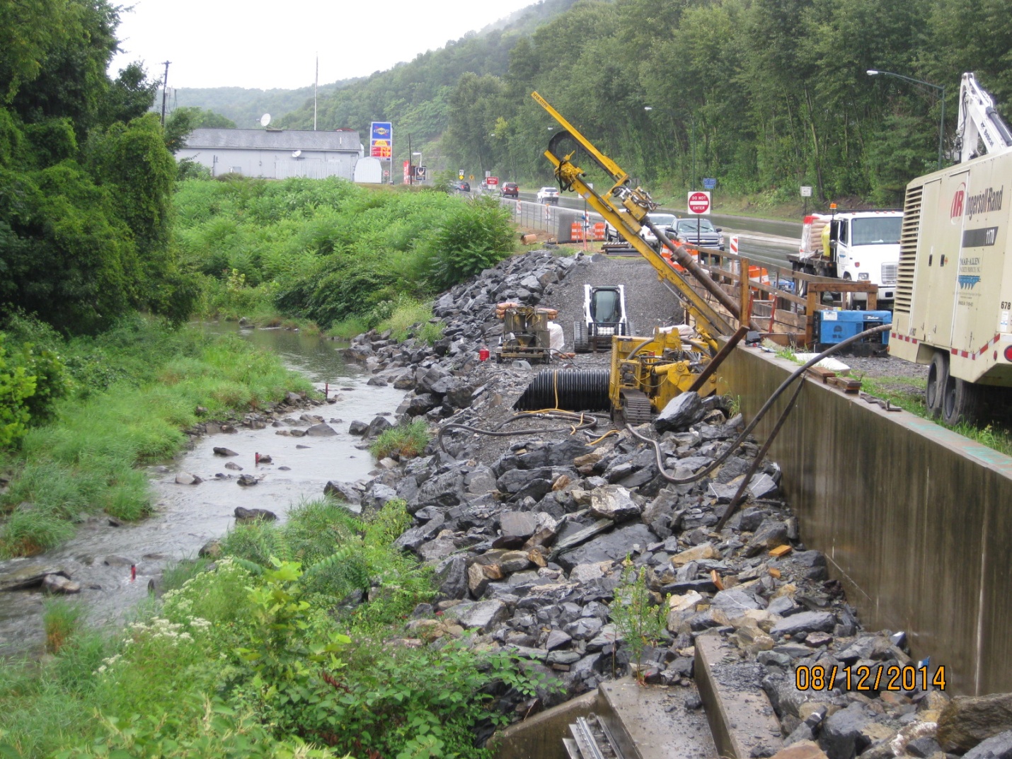
Depressurisation Wells
Depressurisation Wells.
During the course of the week I have been overseeing the installation of 16 depressurisation wells. From my previous blog the purpose of depressurisation wells as appose to dewatering wells is to reduce the pore water pressure, rather than stop mass water ingress into the excavation.
Situation. Although open to debate the exact reason for not completing a full depressurisation system prior to starting the excavation is not entirely clear. However the design authority (C138 Mott MacDonald) had stated the required pore pressure required before excavating below each level. From my last blog C502 (primary contractor Laing O’Rourke) are now having to install the depressurisation system 25m below the surface with only 6m clearance between the working platform and the bottom of the 89 slab level. To make the drilling more complicated, 12 of the 16 wells need the well tip outside of the contiguous pile wall, but avoiding the new crossrail tunnels running adjacent to the Blomfield Box being constructed by C510.
Soil. The soil characteristics are typical of London Clay and the Lambeth Group, over consolidated fine grain soil with laminations of course grain soils. Primarily a low permeability soil with a low voids ratio the soil is very stiff with high shear strength as a result it is extremely difficult to excavate. Added to this it is believed that at 25-30m below the current slab level (83 SSL) are the chalk and silt layers of the Lambeth Group. The risk here is the believed 40m head of the artisan water below within the chalk. Penetrating this would result in a mass water ingress and flooding of the Blomfield box, a potential risk to the project and to life.
Drilling Rig. The drilling rig being used is a Berretta T 57 Geo, which usually has a 10.5 m fixed mast. Given the high strength of the soil, the possibility of pile overspill the drill and the restricted head room the drill was modified rather than use smaller drilling rig with insufficient power to penetrate the soil efficiently. In addition the drilling rig would need to be articulated in order that it could drill at an angle to allow the well tips to be outside of the pile wall. As a result the drilling rig had a smaller mast at 5.5m and hydraulic rams to adjust the drilling angle fitted, all of this was completed in Italy at the expense of C502.
Depressurisation Wells
The well system being used is an ejector system that uses a vacuum to reduce the pressure within the well to set up a artificial low pressure and hydraulic gradient which is intended to draw the porewater from the soil and reduce the pore pressure. The low permeability of the soil means that the seepage rate of the soil is not sufficient to lower the porewater pressure to the required levels set by C138. Unlike an air induced vacuum as used on deep well systems the ejector system induces a vacuum by pumping water into the ejector well tip which sets up a venturi vacuum. The amount of water that is extracted must account for the water pump through the ejector to set up the ventral vacuum.
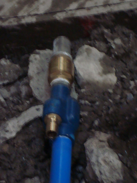
Pictures Right to Left, Well head showoing water inlet and outlet, ejector pump head, water injected through left connection, water removed from main blue pipe.
Drilling Operation.
Angle of Attack. In order to place the wells outside of the pile wall we determined the end location of the wells at 65m, and the location of the C510 running tunnels at 72/73m. This gave us a angle of between 15-20o and at a distance of 2.2m from the pile face.
Drill Setup. As the engineer overseeing the drilling I have been setting up the drilling points and then confirming the drill is at the correct angle prior to drilling. This has been done by using the EDM to determine the Easting and Height of two points on the mast, then using Trig to determine the angle of the mast.
Drilling speed . The speed of drilling is governed not by how fast the drill can be forced through the soil but how quickly the cuttings can be cleared from the well. The drill uses a drilling tip and drilling rods using drilling mud to bring the cuttings to the surface, not an auger.
Drilling Mud. Drilling mud is a mixture of water and additive to create watery slurry. The type of additive used is dependent on the soil type. The drilling mud acts as; a lubricant for the drilling tip, as a well filler similar to bentonite to maintain horizontal pressure to keep the well open and as medium to carry the cuttings clear of the well. Drilling mud is pumped through the centre of the drilling string to the tip, it then picks up cuttings and is forced to the surface. The drilling mud then passes through a series of settlement tanks and then recycled. The types of addictive for different soil types are not an area that I have a great deal of information at this time.
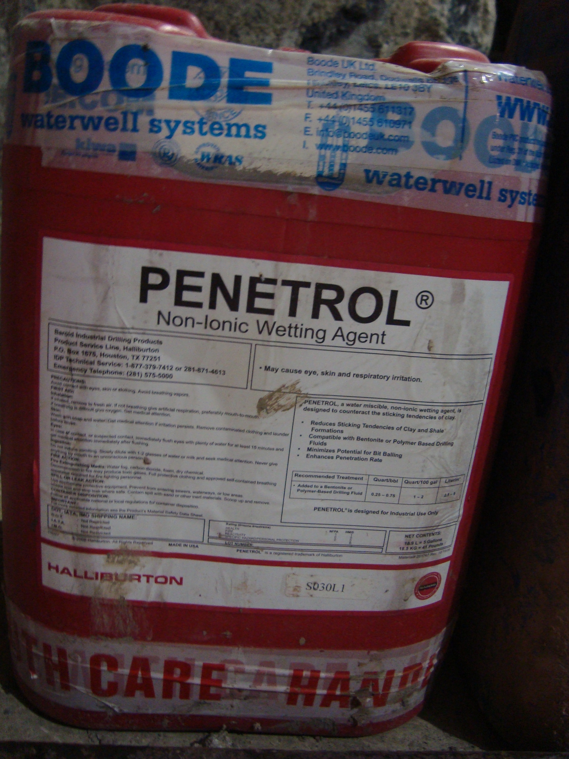

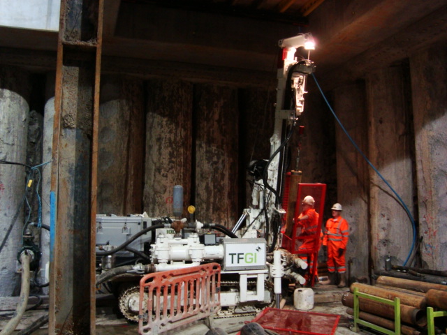
Pictures Right to Left, Drililng mud additive, Drilling rig set at 15 degrees, drilling rig
Another Big Lift
This blog will not add any value by recording reflections but it is one I thought might be reasonably interesting given Peter’s enthusiastic reaction to my last big lift photo in blog 7, DO heaven.
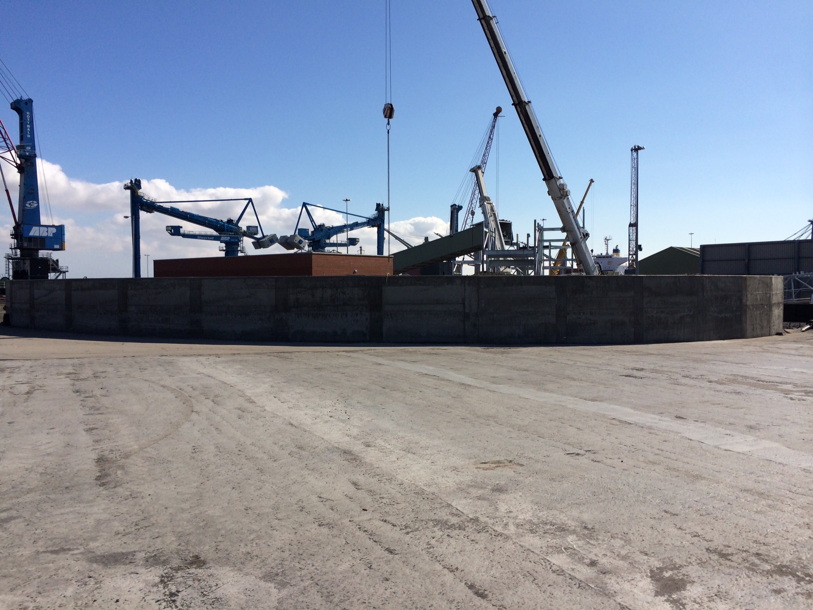
This is one of two 600T £7M Siwertell Container Ship Unloader’s (CSU’s) designed in Sweden, constructed in Italy and delivered to Immingham last week, being lifted off the transport ship by the two on-board 400T cranes. The whole operation went well and the ship off loaded the 2 systems and all ancillary parts in 3 days before departing a day ahead of schedule to Amsterdam (who wouldn’t?!).
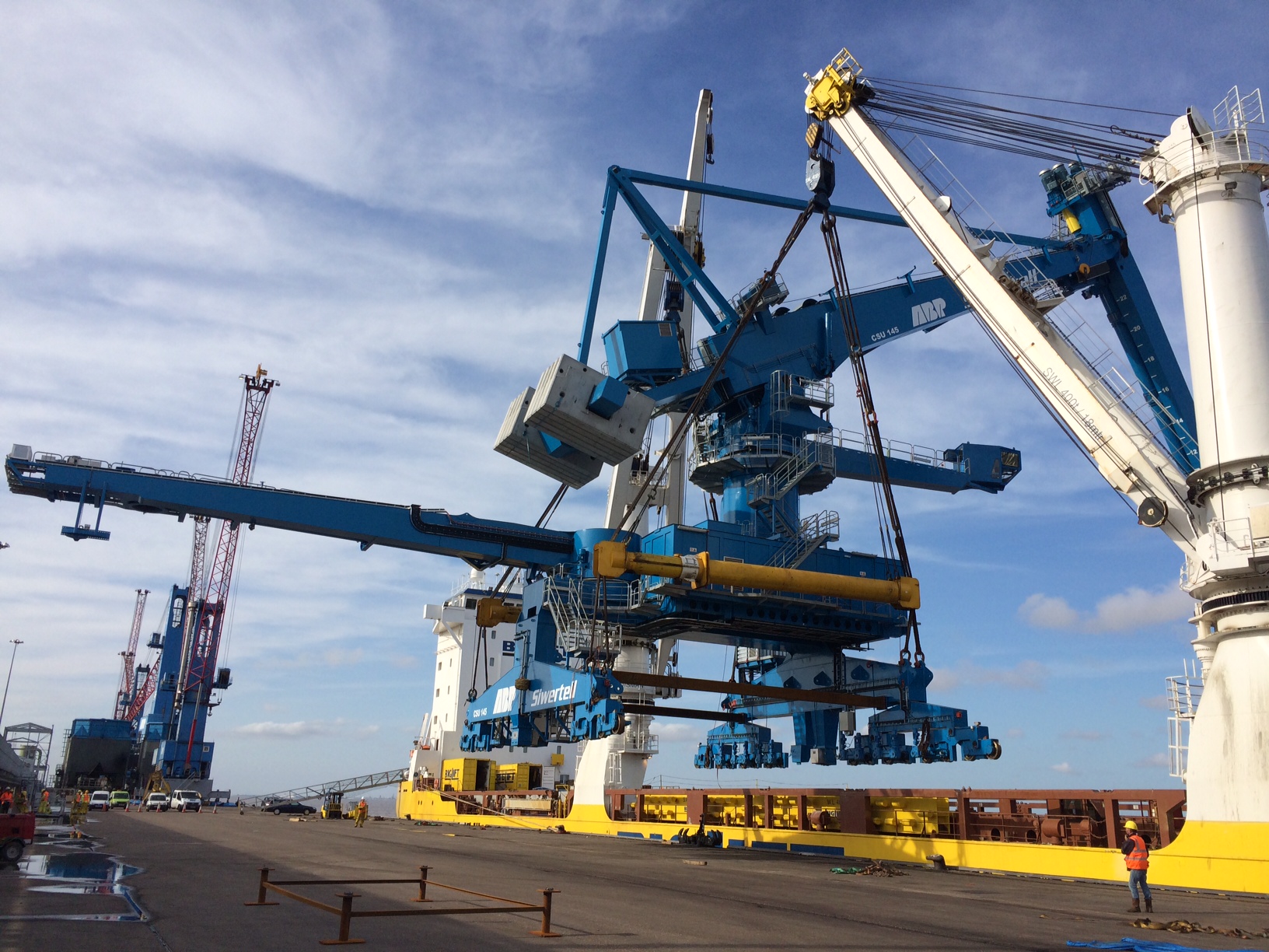
CSU No 1 is lifted from the hold.
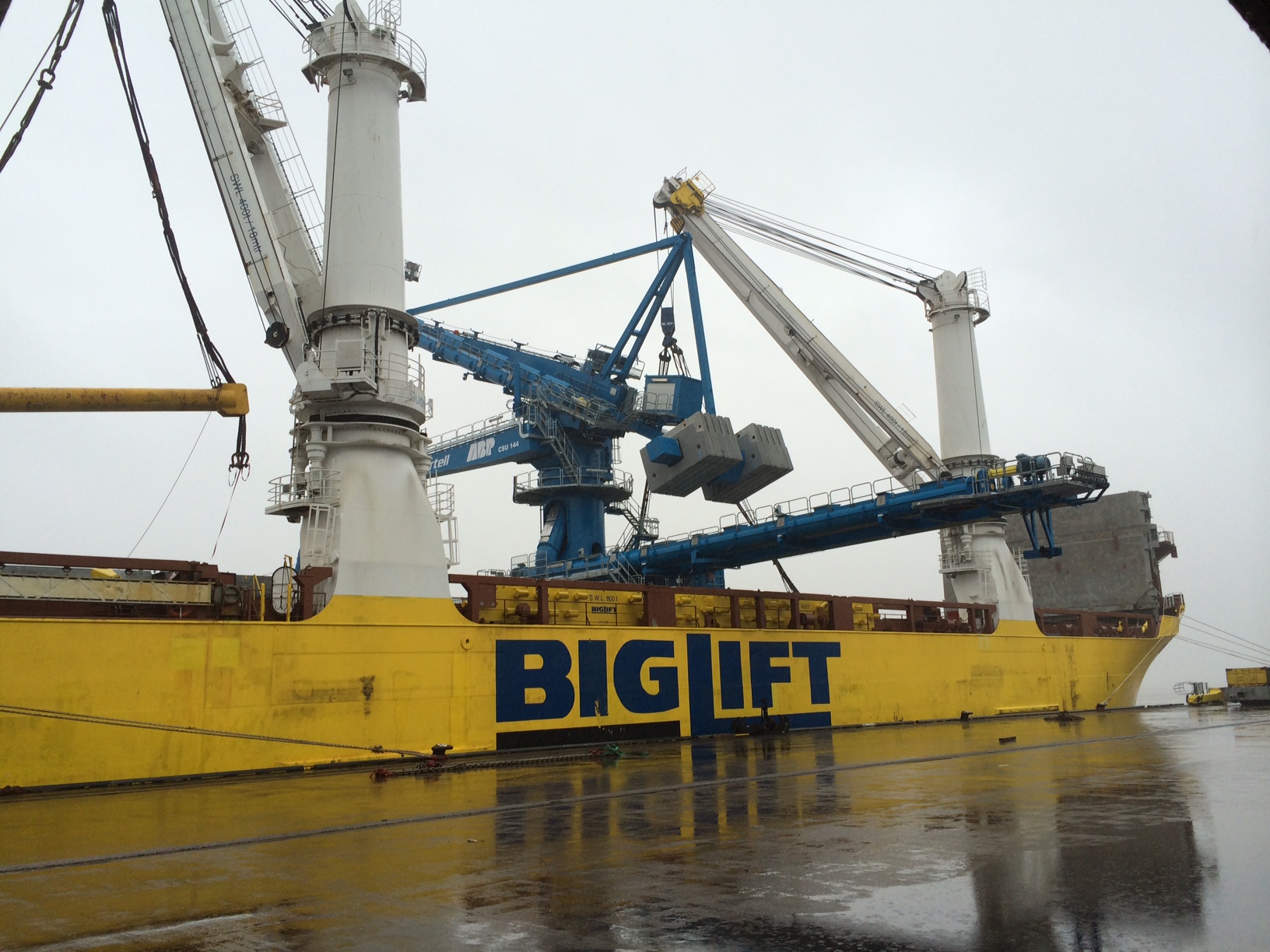
CSU No 2 is prepared for lifting.
These are quite interesting pieces of engineering and are based on the Archimedes Screw principle designed in the 3rd century BC. The rail mounted screw conveyor is an Archimedes screw contained within a tube and turned by a motor so as to deliver the biomass wood pellets from the ships hold to the conveyor system leading to the RC storage silos. This dramatically reduces the amount of labour, energy, spillage, explosive dust and importantly discharge time when compared to the conventional cranes. Whilst initially expensive the discharge time is effectively halved meaning double the amount of biomass ships can be unloaded in a given time increasing ABP’s profit. I expect that they will pay for themselves in a reasonably short space of time. Whilst the image below from Siwertells website is not the greatest quality it shows exactly how the system works.
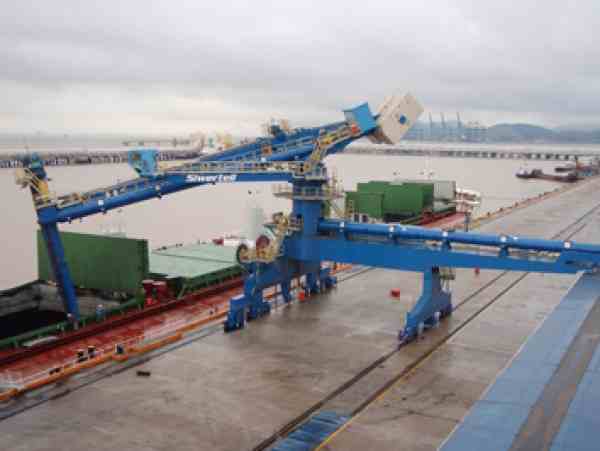
Due to my discoveries during the trail hole excavations at the sub-station there has been a delay whilst the redesign takes place and thus the CSUs have become my focus for the last week or so. This has involved a number of snagging type tasks from clearance and inspections of the rail lines that the CSUs will travel on through to the positioning, drilling and placing of the storm locks and rail clamps that guide the CSU and secure them during a North Sea battering.
Full of hot air….
No doubt you have all had trouble sleeping recently. Understandable…waiting in trepidation for the outcome of ‘McGuirk’s Magical Mix’ trial for the cast in situ secondary lining! In the seminal works, ‘Red Card Moments – Parts 1 and 2’, I detailed the genesis of this mix, following the realisation that there was a national shortage of Pulverised Fuel Ash (PFA). So like a slightly confused contestant on Great British Bake off, I was set the challenge of developing a new recipe for self compacting mix by the site sub agent (who is no Mary Berry!). This mix was to include Ground Granulated Blast Furnace Slag (GGBS) as a cementious filler, in place of PFA. The mix design is as follows:
kg/cubic metre
Ordinary Portland Cement – 270
GGBS – 180
Agg (Limestone, 20mm, 10mm, 4mm) – 1300
Marine Sand – 325
Filler – 100
Admixtures including superplaticiser (water reduction for the low water/cement ratio), stabiliser (modifies viscosity, and eliminates segregation) and retarder(controls the rate of cement hydration). An importanly, 2kg of polypropylene fibres for passive fire protection.
Results
This table shows the performance requirements specified by the client…and how my mix got on!
| Performance Requirement: | KF10 rev 10.0: | BFK024A SCC |
| Cementitious Content | > 320 kg/m3 & < 450 kg/m3 | 450 kg/m3 |
| Water / Cement Ratio BS EN 206-1: 2000 | < 0.50 | 0.50 |
| Density | >2300kg/m3 | 2207kg/m3 average @ 28days |
| Target Flow BS EN 12350-5: 2009 | To be determined during site trials | 500 mm |
| Concrete Temperature | 15°C – 35°C | 26°C |
| Early Age Strength Development | C8/10 @12hours or | 6MPa (achieves 9.2MPa at 24hrs)(please see general comments) |
| Long Term Compressive Strength BS EN 12504-1: 2009 | 28 days > C32/40 | 43.8 MPa(Must exceed specification by current margin, 7.5MPa minus 3.5) |
| 90 days > C32/40 | ||
| Concrete Shrinkage ASTM C341/C341M-06 | <0.03% | 0.003% |
| Exposure class | XC3 | DS2 |
Many of you will not be surprised to hear that despite a valiant effort…it failed. Two criteria. Density and compressive strength.
Analysis
The strength of the concrete is influenced by the water/cement ratio and the relative volume of air in the mix. All Crossrail mixes that I have encountered so far have a specified w/c ratio of <0.5 and in the main, have easily achieved the required density. This mix achieves a figure of 0.5. Whilst I would have preferred a slightly lower figure to achieve a greater strength, this is still within specification, and therefore is not affecting the density in this instance.
The cementitious content adheres to the specification of no more than 450kg/m3, and so cannot be increased. Further, at no point can the mix achieve a temperature of 70degrees C during curing. Using thermocouple data loggers I recorded a peak temperature at the core of 66degrees, so I dont feel I can increase the proportion of cement for fear of too much heat gain.
Therefore, I am focussing my efforts on the volume of air in the mix. The low density may indicate a higher than normal volume of air in the mix. Crossrail have an air entrained mix which is used as a sacrificial medium for the Tunnel Boring Machines to ‘pull’ their way through the station boxes on their drives. The air entrainment has left them with a similiar density to my mix at around 2100kg/m3. This mix is designed to have a relatively low compressive strengh to allow the TBM to easily plough through it. I therefore suspect something in the mix causing it to retain air voids which reduces the density, and further the compressive strength.
Polyfibres
By comparison to other mixes in the project, the only real variable in this mix, is the addtion on polyurethane fibres. Following a series of high profile tunnel fires and the increased threat of terrorism, the safety of underground structures have gained public atention. Polypropylene fibres have been developed as a means of passive fire protection to prevent explosive spalling, and maintain the structural integrity of the concrete.
How do they work?
This is quite interesting…so much so that I found myself spinning the dit to my girlfriend at the weekend…before I had a moment of clarity, whereupon I fell silent for fear of getting chucked!
Imagine the concrete is exposed to high temperatures, such as those in a tunnel fire, or indeed my fire trials (Refer to the tour de force that is “I am the god of hell fire!! (testing) for more details). In high quality concrete,t he density prevents the moisture contained within the concrete lining escaping quickly enough. Any voids that are present will become saturated. The heat will gradually increase and overtake the moisture front, whereupon the moisture will vapourise and increase the pressure in the body of the concrete. This increased pressure can ultimately lead to explosive spalling.
Polyfibres are introduced to increased permeability during heating and ultimatley reducing pore pressure. At approx 160degrees they will begin to melt, before disintegating at about 360degrees. This has the effect of providing millions of capilliaries in the concrete which allow moisture to escape. Brilliant…
However….
Having been tipped off by a guarded response by the manufacturer, it seems the particular brand of fibres…IGNIS…have a tendency to trap air in the mix during curing. As a fag packet calculation, a percentage air change of 1% in your mix can affect the compressive strength by as much as 5%. As the mix had cured there wa no means of conducting an air entrainment test on it, but this confirmed in my mind that this was a prime suspect.
Next Steps.
The pressure is definitely on. We are programmed to pour this mix in the permanent works in 5 weeks time. 28day results, plus a 2 week contracted response time from the client for material approvals, puts us behind by a week.
I have initiated two trials, whih were poured this morning. The same mixes, but with two alternate fibres: one from the same manufacturer, one from a competitor. Initial results as follows:
Fibremesh 150.
Slump/Flow. – 660mm
Ambient temperature. – 15.7°C
Concrete temperature. – 17.6°C
Fresh Density. – 2275
Air Content. – 2.1%
M320P 32F.
Slump/Flow. – 640mm
Ambient temperature. – 14.5°C
Concrete Temperature – 19.7°
Fresh Density – 2270
Air Content – 3.7%
NB. The air entrainment test is not a requirement byt specification, but I requested it given my theory that air content is at the heart of this. Using previous mix performances, and the fag packet from above, I reckon the percentage of air content in the first, failed mix could have been upto 10%. The result above are a good start
Testing
I have taken a total of 30 cubes over the two tests, which will allow the following (increased) testing regime. Those required by the spec are highlighed. In addtion, cores will be taken at 28days the test dry shrinkage.
12hrs – 3 Cubes – Crushed at 27 Aug 14, 1930
24hrs – 3 Cubes – 28 Aug 14, 0730
7 Days – 3 Cubes – 03 Sep 14
14 Days – 3 Cubes – 10 Sep 14
28 Days – 3 Cubes – 24 Sep 14
56 Days – 2 Cubes – 22 Oct 14
(2 spare)
In order to expedite this, I have gained provisional agreement from the client to submit a Materials Compliance Report at 14 days in the hope that I can show a marked improvement in material strength against the first mix. If Im really lucky it may have gained its 28day strength by then, in which case they will approve subject to dry shrinkage results at 28days, meaning McGuirks Magic Mix will be holding up the ‘cross’ in Crossrail!
Safety is not a dirty word…
Safety has been the mainstay of my last couple of weeks. Whilst hierarchical eye-brows were being raised at the photos I continually produced showing a lack of grip of PPE on site by the SSHO, I did some more digging into the site safety. What was initially a little thread pull, turned into a set of pants falling down around the ankles!

Grouting about tie backs (before eye-pro!)
Following installation of the walings and allowing a week for the grout to cure, we have just completed the pull testing on the anchors at 133% of design load. On a site visit to observe the installation of the soil anchors and grouting, I was again hit by sub-contractors without eye-pro, some without high-vis, and others with no hard-hats. As mentioned in previous blogs you may have realized my frustrations at the inability of the QC manager who is double hatted as the site safety officer (SSHO) – hence my decision to ramp it up a gear as my initial hand-holding and constant on the spot rectification clearly handn’t worked. Safety clearly wasn’t in the psyche of the SSHO nor was the understanding of documentation, briefing or indoctrination. I enquired from the operators as to whether they had safety briefs upon arrival on site – the answer all round was ‘no’. Further questioning turned up no hot works permit for welding (as per USACE regs), no accessible first aid kits or knowledge of their contents, no eye wash, no material specs on hand, no accessible emergency plan with routes to hospital etc etc…it went from bad to worse. Upon my return to the office and back briefing the Area Engineer and H&S coordinator, I immediately drafted a dismissal letter to the contractor’s CEO for removal of the SSHO. Somehow the CEO later managed to calm down our Area Engineer, by the promise of a rectification plan within 72-hours and discipline of the SSHO.
The rectification plan has been pretty thorough with the additional intent of bringing a 3rd party to conduct an independent safety audit. The QC has improved dramatically, with the QC manager for the first time intently conducting 3-phase (prep, initial and final) briefings and inspections correctly and with all involved rather than on the back of a fag packet and solely him and the foreman present. I tend to find that safety goes hand in hand with the QC as I would suggest good safety is a function of sound, comprehensive QC. However, my safety ‘feelers’ remain alert so I have gone through the Accident prevention plan (APP) with a fine tooth comb as it is only the risk assessments and CoC diagrams that have been updated since the first 2 phases of the project that were completed last year. What could very well be a scene from Monty Python, was when the USACE H&S manager decided to check the emergency contact numbers in the APP, as they curiously were not 911?? The telephone answer was: ‘’Hey, this is Misty’s bar’’..once the H&S guy had picked himself up from the floor, he managed to do some further enquiry to realise that till not so long ago the bar was the manned telephone for any out of hours fire emergencies as Danville’s fire service was a volunteer service (who presumable were permanently in the bar??). It wasn’t still the case, cue more knuckle rapping. Needless to say the contractor’s rating will be rock-bottom at the end of the construction project.
So, questions I’ve been asking:
- Why did we approve this SSHO, when his CV shows no safety management experience on it other than a 30-hour online course? (Answer: there isn’t answer; we dropped a ball and let it pass under our nose a long time ago!)
- How did this contractor win this contract when it is becoming apparent that they have minimal experience working with USACE (other than a single roof job), no experience working with levee systems and it is becoming clear they are purely a management layer for gaining works and then subcontracting everything out…I also have my assumptions that the APP was written by an external party, as supposedly the SSHO on my site is the contractor’s corporate director of safety…he doesn’t even follow his own APP rules nevermind USACE’s. (Answer: this project was put out to bid amongst ‘small businesses’ – those with an annual income less than $25.5mill. Tender evaluation for such businesses are done by contracting division in Baltimore head office and the dept deals with over $1bill of projects annually…I therefore get the impression that projects such as mine are fast-tracked and minimal resources are allocated to the technical and managerial evaluation boards – I hope to explore this a bit more when in Baltimore for Phase 3)
Negotiations and change orders have now been put to bed for the north end shoring system, the damaged drainage pipe running through the middle of the site, as well as me sitting down with the sub-contractors designers to discuss new site dewatering systems – the longitudinal extent of the excavation was further out than originally thought, especially with the heightened water levels (see pink flagged pegs in river). Instead of the dike system in front of the excavation, we have planned to dam the water upstream with jersey barriers, sandbags and plastic sheeting, whilst pumping the water around the site in addition to the smaller dewatering system within the excavation area. Other options were to change the size of rock armour being used to allow for a steeper slope thus a tighter toe. A lot of our ideas are hamstrung by Public Law 84 for disaster operations, Pennsylvania’s dept of environment permitting and the timeline for which dewatering is intended to take place.
Looking south through the site; note the stakes in the river showing extent of excavation hence the need for a rethink on the dewatering plan
Excavation down to approx 10ft; wales now attached awaiting tie back performance testing.
In other news, Emily and I were kindly given tickets to a pre-season NFL games by a fellow USACE employee for last Saurday evening – what an experience…USA testosterone in all its grandeur!
The pipe-jacking saga continues…
I tried to post this before my holiday, but it seems that WordPress and I don’t get on that well so here I go again 4th time lucky!!
Well this is my 3rd attempt at a blog as first my computer turned itself off then the site crashed whilst trying to save my work. I am off on holiday in 1 hour so I will be quick!
For the last 6 weeks I having been waiting to be able to write a great blog about pipe-jacking under Battersea Park Road with pictures of the launch shaft or some pipes going in. But alas no, we are now going back to looking at different methods because it is too expensive. To cut a long story short the client’s representatives (T&T) and client (BPSDC) nearly had a fit when the £75k provisional sum wouldn’t even cover the launch shaft. Due to the soil type (Terrace Gravels) and water table above the pipe-level, the costs have escalated to £960k! Cue lots of panic and many meetings questioning how on earth it had become so expensive. Here’s why:
Due to the likelihood of hitting an obstruction under Battersea Park Road Bridge the open-face pipe-jacking technique was decided using a 1.2m diameter ID pipe allow miners to excavate inside. Due to the groundwater, this would require de-watering along the full length. As the bridge covered half of the 75m the de-watering regime would not be able to achieve such a large radius of influence without potentially affecting the railway lines 10m from the pipe. Therefore resin grouting would be required for the last 35m. So what was once around £250k for the pipe-jacking alone ballooned to nearly £1m once you looked into the detail design.
Despite my best efforts to explain this with the sub-contractor T&T looked at alternative solutions such as micro-boring and a representative from Barhale came along with his sales pitch. He tried to say that pipe-jacking with miners over 25m went against HSE guidelines (our H&S person then dispelled this as it is allowed with safe systems of work in place). He then said that micro-boring would save lots of money as de-watering and resin grouting would not be required. T&T thought that this was the golden chalice and they put a halt on all pipe-jacking work and made us investigate this more. Since we had already done this exercise back in March less the pricing side of things it wasn’t too difficult to highlight the constraints for the micro-boring. The big ones being: if it hits a boulder over 1/3 the size of the pipe, or timber or steel, it gets stuck-a cost of £350-500k and still no pipe under the bridge with no back-up plan. If that wasn’t enough to put you off then the installation of the reception shaft would need to be in a public cul-de-sac over the trunk main. Diverting services and digging up the street is also not a cheap option. A representative from Terra another tunnelling company also came in to explain this and suddenly T&T’s golden chalice turned into a poisoned one (and I refrained from shouting “told you so!!”). Now we will not get the job done by our deadline of the end of the year when the Northern Line Extension starts at the south of the site in Jan.
So it looks like we will be back to pipe-jacking when they make their mind up this week and I have left the 200 pages of Risk Assessment and Method Statements and temporary works designs with Network Rail for approval. Now I am off to Turkey kite-surfing for a week so next week should be quite interesting!
HV Cable Strike!!
If you want to see a pained expression worse than Ryan’s when he realises the last chocolate digestive has been taken, walk into your offices and utter the words ‘we’ve had a HV cable strike!’
My last blog commented on the progress I was making towards my DO’s with work on the Dwarf Wall, HV ducting and student mentoring. I have completed 192.652m of the 619.310m Dwarf Wall, which is as far as I will now take it. This is no bad thing as I got as much experience out of it as was likely. The student has fledged and flown the nest to start work on the second rail load out silo for IRFT 2.
The HV ducting and deluge main proved more challenging than it first appeared and there were a whole host of learning points from the experience.
As part of the preparation for the work I organised a GPR survey to identify all the existing ABP services crossing the area we would be excavating through. This all formed part of the various permits and RAMS I completed, as mentioned in my previous blog and in detail for AER2. We successfully undermined 5 sets of existing HV lines at various points, a number of live water mains and several fibre optic telecommunication cables without incident. On the last HV cable crossing this happened:
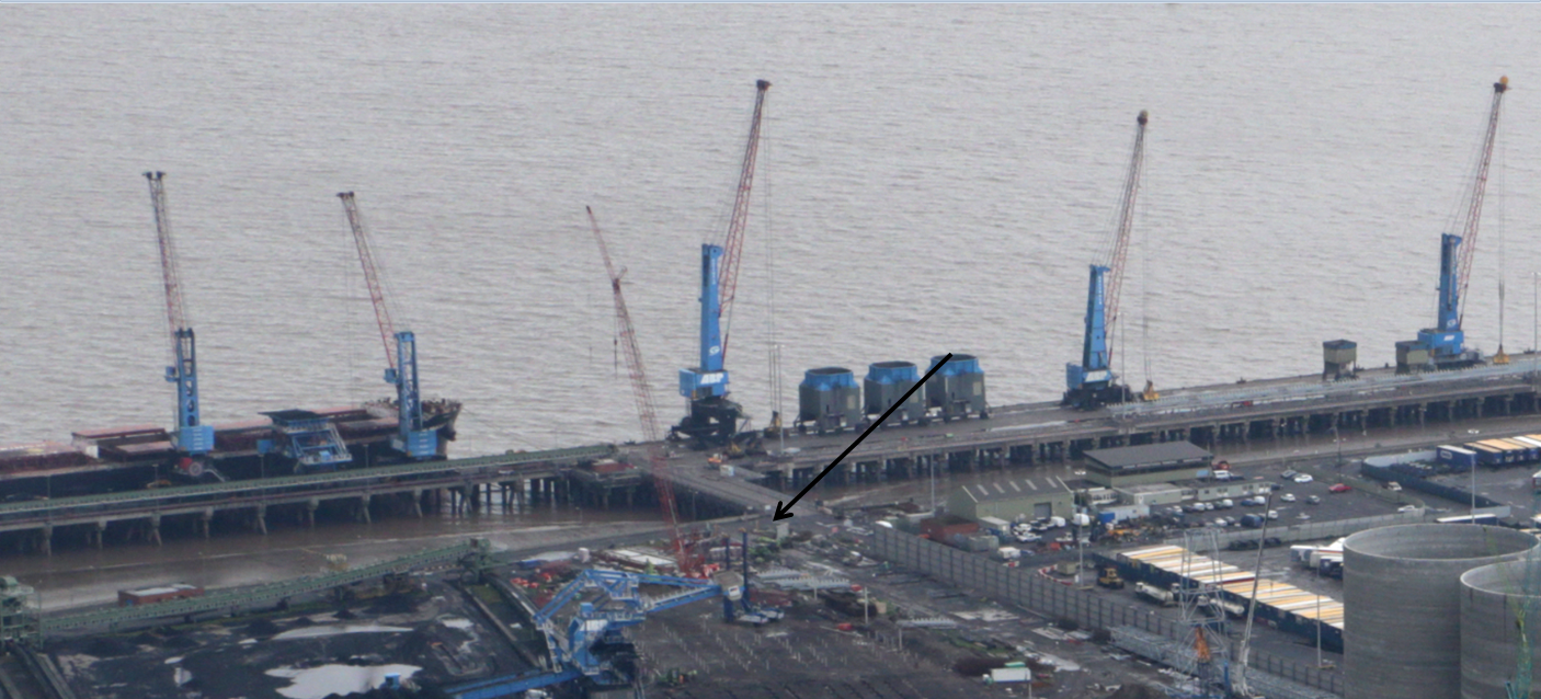
Unfortunately it was the primary HV line to the main unloading jetty (location shown in photo below), powering all the infrastructure including the cranes, where 2 container ships were being unloaded at the time. It was also during the crossing of the main access road to that jetty that we were only allowed access to for one 12 hour period. Balls.
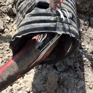
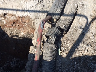
The first photo shows the primary 11kV line that we hit and the fibre optic cables that ran in parallel. There happened to be a secondary HV line directly underneath the primary that subsequently proved useful. By the skin of our teeth only the armour surround to the cable had been pierced not the inner cable and it never went bang despite being wrenched a few inches up by the excavator bucket.
So what happened??
This was my section of works but in the greatest tradition of every troop commanders favourite sapper, I wasn’t there at the time boss! The previous night I had issued the permit to dig, briefed the team (including the engineer who would cover for me in the morning) and prepared the road closure procedures for the following day. The route of all the cabling was identified through the GPR drawings, checked with a CAT scan and sprayed in red onto the road. The following morning the team set to work and the road tarmac was cut using the road cutting saw.
This is where a small series of errors came together resulting in the strike.
The road cutting saw creates a lot of dust that when suppressed by the accompanying water unit covers everything around it in a thick slurry, including red spray paint marking routes of HV lines.
The team that I had briefed the night before got pulled onto another task early on in the works (operator availability as ever) and the replacement crew, despite having also attended the evening brief, were not given a thorough HOTO or up-to-date brief by the engineer or foreman. The tarmac line that had been cut was assumed to be the line of excavation to the full depth of the ducting, as the red spray was no longer visible they just cracked on and dug away.
The engineer left in charge hadn’t noticed the red spray was no longer visible, assumed everyone had understood the brief as well as himself and was taking photos of a manhole to one side when the incident occurred.
The foreman working on the task had only arrived on site the day before, had been briefed but wasn’t really ‘acclimatised’.
I’m sure you’ll all say ‘yeah yeah’ but my timing couldn’t have been worse as I walked into the works area to hear the foreman shout ‘whoa, whoa, whoa, that doesn’t look too good …….ah Joe you’re here……take a look at this…..’!
So what did I do??
After calming down and realising nothing had gone bang, nobody had been BBQ’d, (thanks Harry for those inspiring HV strike H&S videos), and everything on the jetty was still working, I basically conducted a 4C’s operation! Train hard fight easy and all that.
I phoned my section manager (who thought I was joking) and informed the on-site health and safety advisor.
I soon had a battlefield tour on my hands as every man and his dog came down for a nosey and a photo.
Everyone was fairly pragmatic about the situation, some more so than others and I had to laugh when the foreman suggested poking it back into the ground and covering it in concrete before the client found out!
The main HV line serviced the whole jetty, the secondary line powered just the cranes and ancillary equipment ie the vital unloading equipment. After much discussion it was decided that the power would be switch to the secondary line for 2 hours so the primary could be inspected but allowing the unloading of the ships that were docked to continue. Once complete the main line was switched back on and a cordon was put into place until the ships had been completely unloaded. This then gave us a 12hr window, between the high tides, a couple of days later to get it fixed prior to the next ships arriving. The damages for a ship in port not being unloaded are huge, so realistically that was the only choice.
So what I have learnt?
Technically.
GPR Survey. The investment in a GPR survey is worth every penny and I cant recommend it highly enough in similar circumstances. The amount it reduces the risk alone is worth the investment. The cable we hit, we knew the location of, which makes it even the more frustrating. The CAT & Genny is very good for identifying services but proves difficult on our site due to the industrial nature of the fill that makes up the top 5-7m of ground as it is full of metal and old cabling. In addition the clients existing service drawings, that formed part of the initial tender, are woefully out of date and hugely inaccurate and some of the electrical cables service night time facilities so the CAT SCAN may miss them in the day, the GPR survey will not. The GPR survey allowed us to identify the services and then we could use the CAT SCAN to confirm the locations as it much easier to use on this site once you know the path of the service. I was also surprised with the accuracy of the GPR depth estimations as 90% of the time they were spot on. This has led to my insistence on getting the same done over my new site for the substation build I will be conducting, as there are a number of services including HV around the existing substation that mine will replace. I suppose the ground is a risk whatever way you look at it!
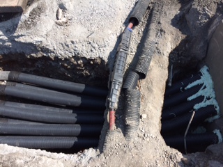
How to fix HV lines! The armour was cut away and replaced followed by a mould that was pumped full of resin to reinstate the outer casing. This was then re-sleeved with the ducting. We also used the 12 hour period to complete the undermining of the lines and fit our 12 ducts into the manhole as can all be seen in the photographs below.

Managerially.
Health and Safety. Don’t skimp on the paperwork. The H&S advisor rightly conducted an investigation and after his initial enthusiasm to hang someone was dampened, he used the opportunity as a lessons learnt scenario. He concluded that the paperwork was actually to a standard that he had rarely seen on the site! The RAMS, drawings and permits to dig I completed were comprehensive, up-to-date and everyone had been fully signed up so my arse was covered. I even suggested an additional measure that has now been adopted on site similar to the sign off sheets seen in the military when a memorandum is circulated to ensure everyone has read and understood the permit to dig. Up to that point everyone had to read and sign the RAMS but only the operator and banksman had to sign the permit to dig that contained the up-to-date drawings and service details.
Communication. Absolutely key. It was clear that much of the error had come from the change-over of the plant operator and banksman and the lack of communication between the team largely assembled in the morning. There were various levels of information amongst the team and everyone assumed everyone else knew what was going on. The lack of communication invariably led to the strike and was the main learning point from the H&S investigation.
Control. I wasn’t on the site at the time of the incident (have I mentioned that?!). I had handed over to another engineer the night before who knew of the HV line (I had sprayed it out with him) but he had been taking photos of the manholes we had constructed the day before when the incident happened. If I had been there I would like to think that I would have been more resistant to the change of plant operator and at least stopped the incident as I had lived and breathed those services for the preceding weeks. I was a little disappointed with the whole episode from a personal perspective as we had conducted a number of crossings to this previously without incident, and we stumbled at the last fence.
I have now completed my summer leave and have started setting up my own mini-site for the sub-station construction I have been given the independent command of. The design is yet to be completely finalised but this week I have cracked on conducted the GPR survey (as mentioned above) the CAT SCAN and dug a number of trail holes to confirm the services. I am taking the design co-ordinator down to the site this afternoon as a number of my discoveries (railway lines, CFA piles, pile caps, sheet piles etc) are likely to force additional redesign – watch this space.
Things are going wrong!
The mechanical subcontractor is the worst performing subcontractor on site!! They have today after three months of work have realised they have did not design their expansion of their chilled water pipes correctly. This is causing huge problems as currently the system is a fully Victalic system and now they want to weld every change of direction. Considering a large amount has already been hydraulically tested, signed off and lagged, with cable tray below this is going to be major re-works. Also going through the programme with them a completion date of their plant room which will supply chilled water to the Central Communications Room CCR2 an essential part of the hospital, which has a hand over date of December fully operattional ie it has chilled water running to it, now has a completion date of mid feb……not good.
On a positive note the Power Available programme which has been running since April is nearly complete, we have all three substations ready for commissioning, I have attended all the Factory Acceptance Tests (FAT) for the equipment, we have had some huge logistical problems with some of the larger switch boards. Overall has been a very good experience. We are having large problems with the Client changing its mind and also delaying works by
sitting on very small decisions, it is frustrating how so many people don’t like making decisions and we have been trained to make decisions. We are now getting into the real detailed design of how everything operates and it is clear that the detailed design is truly lacking. There are fundamental parts of systems that have not been thought about correctly, for example the Reverse Osmosis water, chilled water to CCR2 (no mechanical separation) and the whole BMS interface with equipment. this is just to name a few, the great side its keeping me very very busy, with thinking about design, functionability on site and cost.
I have also been responsible for the Northern Green Space as a lad was a way for 5 weeks, this involved all the connections to and from the building for the two fire tanks and two rain water tanks. This brought around a new dimension to works as I had a new set of dead lines set by the infra guys outside, who I was pushing as we wanted to run the Syfonic drainage to the tanks instead of flooding the basement. Overall busy times and the pressure is on as the completion date of 30 June 2015 is dramatically looming and there are some fundamental things going wrong, mainly the mech subbie…
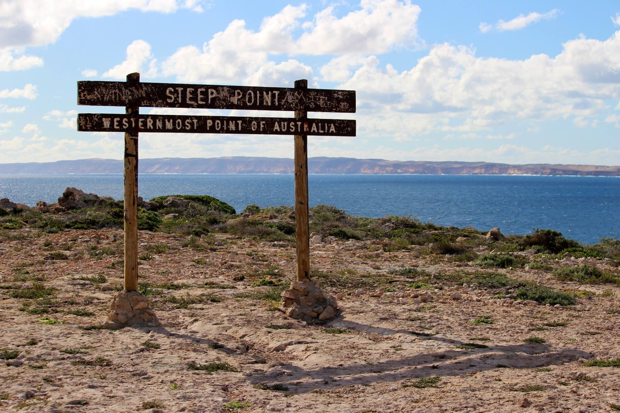
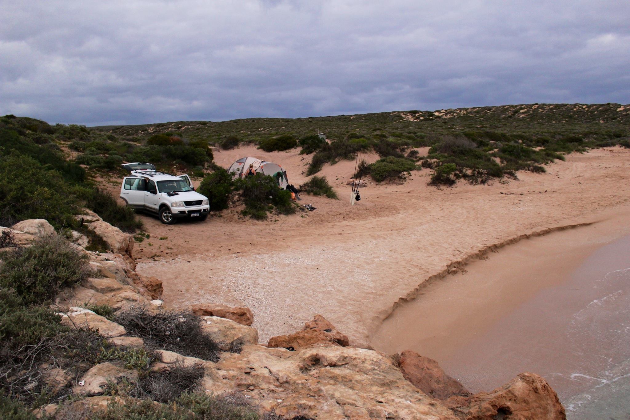
On a positive note spring is here it was a lovely 25 the other day and is warmer at night now, Hannah and I had a great weekend at Shark Bay which is such an incredible place, but a 10 hour drive!!