140 Elephant Hangers
The South Bank Tower extension from 30 to 42 storeys is based upon the requirement that all vertical loads must be transmitted down the existing core to the foundations.
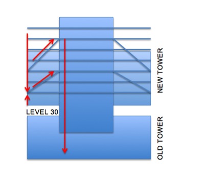
In order to do this, the floors outside of the core will be hung, supported by angled steel bars that drop down from 2 or 3 storeys above. In plan, there are three hanger locations, NW NE and SW corners (see red below). Each corner has an upper set and lower set, as can be seen above (blue diagonals).
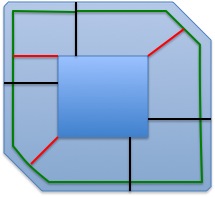
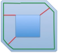
The NE and SW hangers (in red now above) each have three bars. Each bar is 100mm in diameter and is to be supplied and installed by Macalloy. Since the NW hanger supports a small floor area there are only two bars on each set. The Macalloy bars pick up load from a ring beam (in green above). The ring beam spans from the wing walls (in black above) between Level 30 and Level 35. Above Level 35 there are no wing walls and the ring beam extends around the entire building (as below).
The challenge therefore is taking the high resultant verticals loads (7600kN in disproportionate collapse = 140 elephants) that drop onto the Macalloy bars and transferring it safely into the RC core. This steel to concrete connection (the hanger) is the key element of the building and the lack of detail from our Structural Engineer has added a degree of friction to the planning and design of these elements (ref last post).
Constructability
The 12-storey reinforced concrete tower core extension is going to be built with a slipform rig. The slipform rig will not allow the corner hangers to be installed as the slip passes each hanger location. Therefore large pockets, or voids, will be left at each hanger location. Over the past month I have worked on the size of each pocket, what infill (or strengthening) is required around each to ensure the temporary stability of the tower, as well as the sequence of offering the hanger into the building and making good.
The general sequence is
1 Slipform launches from Level 30
2 Slipform leaves pockets at each hanger location (six in total)
3 Floor plates internal to the core follow the slip with a 3 floor delay
4 Slipform reaches Level 42 and is dismantled
5 The floor slab adjacent to each hanger is post tensioned, once the concrete is up to design strength.
6 Access is now possible to the hangers with the crane and the hanger is installed.
7 The Macalloy bars are attached and can suspend the steel frame exterior to the core, and later composite slabs.
The Steel to Concrete Connection
The principle of the corner hanger is to resolve the diagonal Macalloy force into a vertical and horizontal components.
The horizontal force component passes along post-tensioned cables that are anchored within a 400mm thick slab. Macalloy rods are planned to be used (not confirmed) and they will lie in the middle of the slab with no change of eccentricity. The PT slab is heavily reinforced to allow the tensile loads in the tendon to pass right through the entire core slab. Outside of the PT slab the floor is only 200mm thick.
The vertical component employs both bearing and shear keys (within the hanger) to transit the vertical compression into the walls of the core. The shear key uses three 350x350mm SHS sections (filled with grout) to engage the concrete within the walls. The key issue for us is maintaining wall reinforcement continuity into the hanger.
The way we plan to do this is by leaving couplers accessible on the edge of the void as the slipform passes. The corner hanger will be offered up in two phases. First the inside plate, with SHS sections, is lifted and positioned. Then the rebar is fixed within the hanger (and attached to the couplers left in the walls), the outside plates are welded on, and finally the hanger is filled with concrete.
The risk here is that air pockets might form within the hanger and this will significantly affect the bearing ability of the hanger.
The Issues & resolutions
- Size of the void
o We have opted to weld the hanger on site. This limits the size of the void since the lapping of rebar will happen inside, instead of outside the core. However the quality of the weld may be reduced. My input was to conduct prelim analysis of the viability of options an then a detailed examination to highlight issues to the Struct Engrs.
- Rebar displacement and continuity inside and around the hanger.
o The SHS sections block horizontal and vertical rebar. The base plate blocks vertical rebar.
o Therefore holes will be drilled in the base plate and rebar will be displaced to avoid the SHS sections. The detailed examination again identified issues and I was able to propose minor design changes.
- Temporary strengthening around the voids.
o How much strengthening is required for local and global stability? How will it affect later construction? What is the cost?
o I looked at RC strengthening, steel and proprietary systems. For global stability we are using further strips of RC to be slipped. For local stability issues the use of proprietary systems allows quick installation.
- The PT slab does not extend through the entire core.
o How will this affect the robustness of the core? Mace have not conducted any examination of the detailed design but since concerns have been raised we are now getting a Category 3 check completed on the hangers.
- There is no tensioned belt around the core at the hanger level.
o What is stopping the corner of the building bursting out from inside the core? This will be covered in the Cat 3 check.
- The Macalloy bars will elongate during construction and throw out construction tolerances.
o How do we plan the elongation and pre-set required at the start of construction. Whose responsibility is it to get it right???
o Do we plan to jack (shorten) the Macalloy bars to achieve the required length later on?
o Will the cables need to be jacked in order to achieve a regular force between them?
o These issues are not bottomed out. AKT are not willing to give preset cambers, or dictate the jacking procedure which we are strongly contending. After all, it is their design and concept, not ours, to screw up!
In all, the past few weeks have been the most interesting but stressful. The slipform is now behind schedule, but has now launches and is at level 33. PC Harringtons are paying the price still for not backing up their engineering design team since temporary works were holding up the construction.
When Deck Pours go Bad
So I’ve had a request from one of you excited civils out there to expand upon my throw away comment this morning about a deck collapse on site. I should have known that simply mentioning a concrete pour would have caused a ‘Civil Twitch’
Three days before a site closure for the Easter long weekend a concrete deck pour had been scheduled. In the region of 300m^3 were scheduled to be poured on a deck half suspended over a previously poured concrete slab and half over formwork suspended off a sloped batter. Halfway through the pour the formwork gave way and a partial deck collapsed occurred causing the site to be evacuated and effectively closed for five days.
No one was injured during the incident – Through the use of exclusion zones and Partially due to the fact that the collapse occurred half an hour before a scheduled evacuation rehearsal – The site staff had been prepped and ready for an emergency drill.

Concrete deck pour complete with undersigned additional ventilation/ natural lighting
Investigation into the incident uncovered a number of key failings which led to the deck collapse:
1. The Pre pour formwork inspection by an engineer had occurred a number of days before the pour.
2. A significant amount of rainfall had occurred the night before the pour – enough to cause standing water in the basement of the project– changing the condition of the batter upon which the formwork supports had been placed. (effectively the surface of the batter had water running down it, an
3. The ‘shelves’ cut into the batter to place the formwork supports on were insufficient to distribute the load
4. No post rain, or pre pour inspection occurred the morning of the pour (no Question 2.4 moment, Has the situation changed?)
The result? an industrial investigation, union action, a new site manager and add 4 weeks and thousands of dollars to your program please!
Abercrombie Update
Life at the Sydney business school build has been suitably hectic, hence my recent lack of blogging, For which I thoroughly apologise. A deck collapse on a concrete pour before Easter put the construction program back 3 -4 weeks and ended the reign of the somewhat haphazard site manager. The new site manager has been keen to drive things forward in terms of remediation and it has been all hands to the pump in order to attempt to recover lost time.
Tasks that have been added to my gradually growing portfolio of responsibilities has been the running of the services section of the weekly site subcontractors meeting – deconflicting issues between the subcontractors on site and managing the services portion of the four weekly program in conjuction with the site foremen. As the vertical of the building increases (The western end of the building is due to pour the first slab of the top floor later this week) and formwork is removed from the lower levels, access for services trades has opened right up and managing the trades in the lower levels has become a real challenge,- The application of deconfliction is apparently a new concept! The value of careful (military esque!) sequencing and programming is being demonstrated to the organisation and is gathering momentum. Construction of the higher levels of the building has also required me to design and arrange the installation of temporary, charged fire hydrant and hozereel systems for the lower floors in order to meet increasingly stringent health and safety requirements during construction.
Services ‘Flying in’
This week saw the last slab on ground pour for the main building of the business school, a momentous occasion which has meant that across the site we are no officially ‘Out of the Mud’ which means for the most part that I can begin to stop being concerned (as Angela is) at the risk of In ground services strikes. This is less the two big ones which are coming up – Undergrounding of overhead power cables in the streetway (a seemingly innocuous task less, were it not for the fact that the area in question is a minefield of existing services including a number of high pressure gas mains) and the construction of a new chamber HV substation, in an area that has had temp 3 phase power for one of the sites tower cranes run through the ground. Needless to say I’m heavily involved in designing the methodology for both these tasks.

Apparently, There is going to an HV substation in there one day.
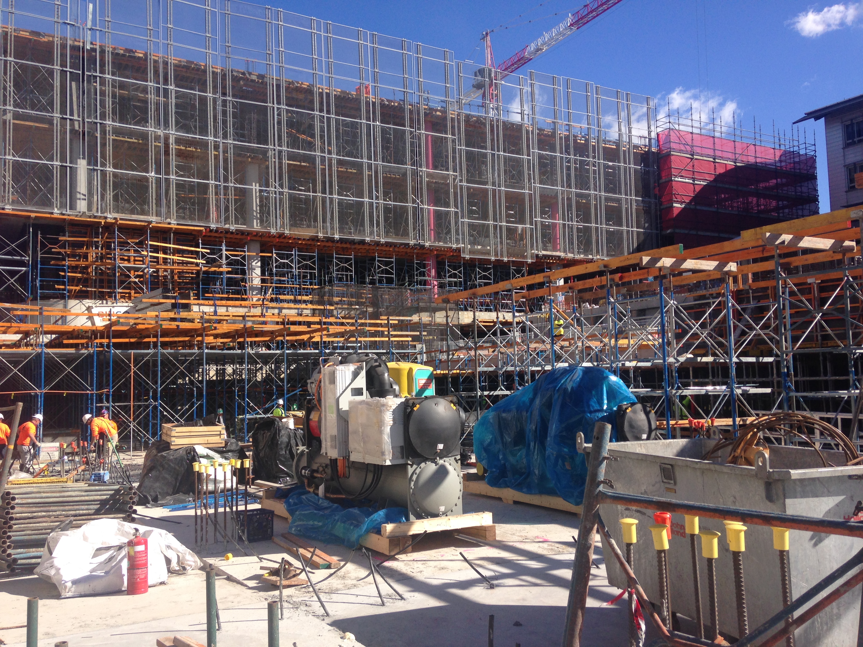
As the building goes up storage for plant and equipment becomes tight. Arrival, unloading and storage of 8 ton chiller required careful planning.
Procedurally I have had my hands full as well – Reviewing and rewriting the Site’s electrical works management plan as well as Activity Method Statements for the installation of services (The overarching Health and Safety Framework for the services installation).
Quality Assurance and problem solving on site continue apace. Delays to the BIM 360 role out has meant that clash detection, recording and solving on site as the services trades role through the building has been undertaken manually, with myself as the primary conduit.

Pressure testing of Ductwork to ensure stringent university and not so stringent SMAKNA standards are met.
The entire services team has now relocated to site, and while the other two members of the team continue to be focussed on completing the design, my focus remains primarily on the construction as well as being the main mechanical services engineer. This will expand over the coming weeks as the Services Manager goes on a 5 week holiday, next Friday, and as a result a gradual hand over of responsibilities has begun to myself and the AV and commissioning Engineer. Sink or swim time. Watch this space!
Stop Stop Stop
As part of the piling proprietary works we were required to remove sections of a reinforced concrete slab with the old Boradgate ticket hall. The slab level that requires breaking sits 108 SSL (street level 112 SSL) and in order to facilitate piling the substation is due to be filled with foamed concrete and clay fill. The purpose of the fill and foamed concrete is to bring the ground level up to street level in order that the piling mattress and piling rig are not working over a suspended slab with a void some 4-5m deep beneath them.
The breaking out of the sections of the 108 slab is to allow remove any obstructions to the piling that may cause the piles to kick and become misaligned. To facilitate the break out we hired a machine called a Brokk which is a small remotely operated breaker and excavator. The great advantage of these machines is that they are able to access confined spaces and break out areas overhead while removing the risks associated with construction workers (operative) operating within these environments. Although there remains a risk of damage to the machine, considered much less of a risk then injury or death to an operative.
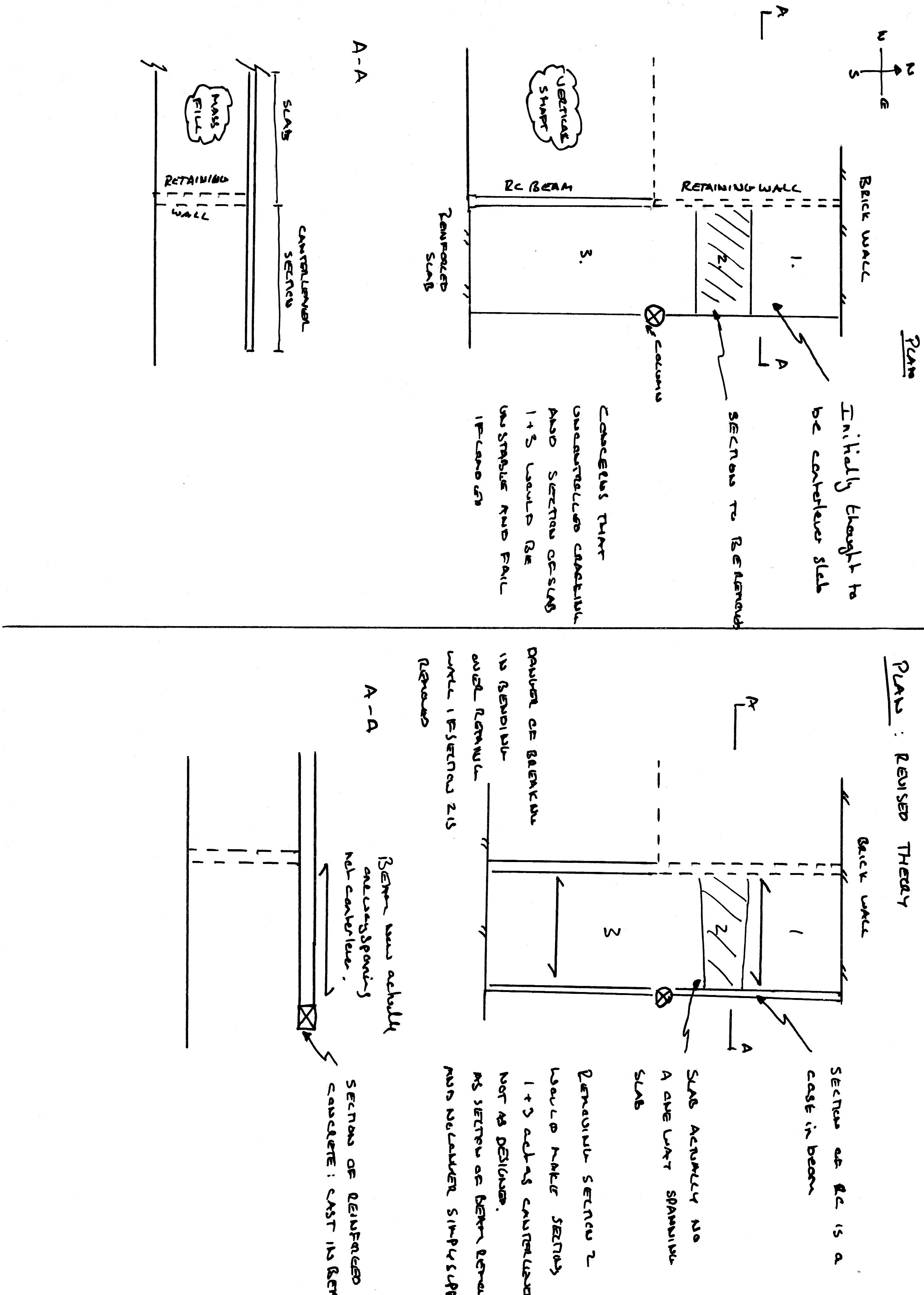
Having successfully remove all but one of the sections of the slab the project manager was pushing to remove the final section but I raised a concern over it appearing to be a canter leaver slab and that we had no way of knowing how the remaining part of the canter lever slab would react to a section being removed. Warnings ignored our project manager continued to push forward with the break out and I found myself with only a limited amount of time to come up with a convincing argument as to why we should not break the slab and an alternative solution.
The area of slab to be removed as a 1.5 x 1.5m section. The section of slab appears to be cantilevered over a small retaining wall with the canter lever wall reaching west to east. The area that appeared to be canter levered is tied into a brick wall at the northern end and then merely sits on top of the connecting flange of a cast iron column at mid-section and then tied into a reinforced concrete slab at the southern end. Between the Column and the northern wall there is only one small supporting strut. Between the column and the southern end the small retaining wall ceases and a vertical shaft opens beneath the slab. My concern was/is that the breaking out of the section would/could result in unpredictable cracking and the failure of the slab presenting a risk of injury or death if loaded. A phone call to the rear guard for some further advice deduced the following:
The area that at first appears to be acting as a canter lever may in fact be acting as a simply supported slab, with hidden cast in beam that spans from the northern wall to the column and then to the southern slab. This would then allow for a one way spanning slab from the retaining wall to the beam. If this is the case then removing a section of the slab would then make the slab work in a way it was not design too with the potential to fail un predictable if loaded. This is of course only a theory, as I have no way of knowing if the edge of the slab is indeed a simply supported beam and I also do not know the make up of the steel with in the slab.
Initial recommendations:
- Remove a larger section of the slab to the north of the column. This would then allow the southern section to act in isolation. Any area north of the column that may have been unsupported and pose a risk of unpredictable failure would be removed.
- Find another way of completing the work.
Final solution:
As a further part of the works we are required to fill the void beneath the 108 slab with foamed concrete. By filling the void first and then breaking out the section of the 108 slab the risk of failure has been completely removed. The order for the works is not important as neither the foamed concrete nor the break out are dependent on the other.
In the words of the great orator “never assume anyone else knows what they are doing” in this case after presenting my theories and recommendations and with no one else having either come up with a recommendation or even being able to prove me wrong we were forced into working to my recommendation. So I hope it all works. May I recommend that should any of you find yourselves in the future be travelling on Crossrail, I recommend that you do not get off at Liverpool street as i have hand in guiding the build…
Holes and rattlesnakes!
There has been little tangible movement on the flood repair since my last blog other than to’ing and fro’ing of submittals from the contractor for his dewatering plan (or lack of), erosion and sedimentation plan and random others such as concrete and pozzolan specs. It has taking even longer when the chain comprises of the subcontractor, contractor, USACE area office, USACE design office and then additional third parties – state Dept of Transport or State enviro guys – I sit in the middle getting annoyed and cross-eyed. Even with my immature engr eyes I have picked up errors in submittals as simple as not supplying the right concrete ‘psi’ despite it being clearly stated in the specs. Despite the paper-pushing, the clock has started for the contractor; I can only persuade and remind them of the repercussions of late completion but this is preaching to the converted somewhat so the ball is really in their court.
I have continued with the QA on the HQ site. Today was my first soiree into the E&M world…..DALT testing! A quick google search as to what exactly that meant – Duct Air Leakage Testing. Thinking I’d be out of my depth, I was pleased to see that in the initial briefing and explanation for 12 of the witnesses (incl me) that it was quickly apparent that only about 2 of them knew what exactly was going to happen having been baffled by a handout of 20 pages of which 2 pages were only relevant, while the rest all kept quiet trying to look both interested and knowledgeable – the veneer crumbled rapidly when the uniformed guy in the corner with a funny accent started asking questions!!
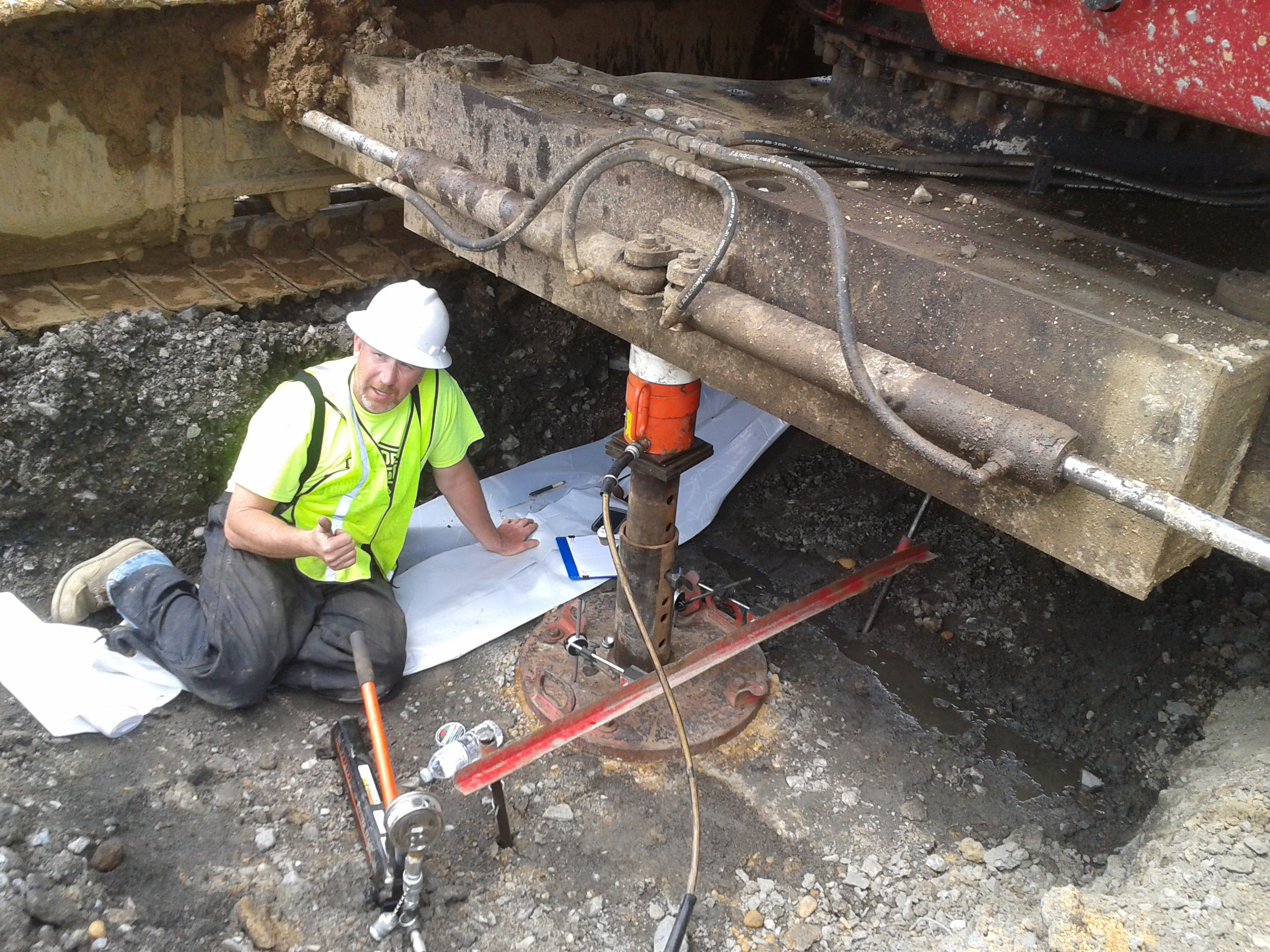
Adjacent to the office is another USACE project I have been keeping my eye on – a large warehouse that has just started foundation work. The ground is a mix of silt, sand and clay and general debris (having had an entire ground penetrating radar scan) with a high water table of approx 0.5m. The line of attack therefore is to build geo-piers (otherwise known as rammed aggregate piers). The technique is exceptionally simple – a 12-15ft shaft is formed by the ‘rammer’, it is then withdrawn and layer upon layer of aggregate is poured and rammed/compacted into the hole – see below.

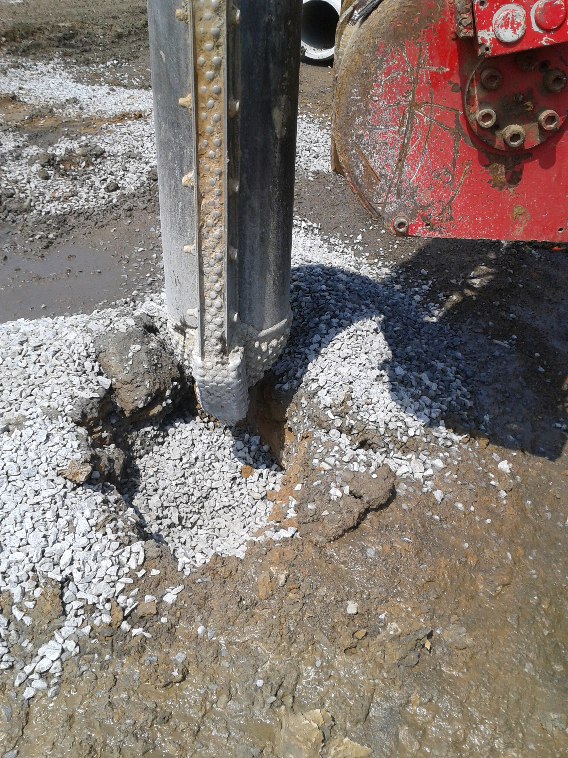
I sense John putting on his reading glasses now….rather than our typically taught shallow or deep foundations, these are known as ‘intermediate’. The rammer tool has 45deg edges to press the rock laterally – this ‘preconsolidation’ technique pre-strains and pre-stresses the soil below the drilled bottom, creating a bulbous base of aggregate upon which succesive layers are piled and compacted (each layer no more than 0.3m). The ramming therefore creates a very stiff dense rock pier (”load goes to stiffness”) but also improves the strength and stiffness of the soil surrounding the pier, through compaction >> increased lateral stress >>increased effective stress >> increased shear strength (Mohr’s circle) . It does however involve a huge amount of piers, 3600 for that matter under a warehouse approx 200m x 100m, but each rig can complete approx 50 piers per day; one more is inbound (with a top hopper). In this case no steel is being used, but it can be incorporated to prevent uplift.
One day in we conducted the modulus test on one pier – the top foot (sacrificial) of pier was hoed back, while a pressure of double the design load was placed upon it (550kN/m2). Settlement was then recorded as pressure was increased, as was the rebound when pressure was released. We await exact figures and analysis but down and dirty figures were a total settlement of approx 8mm, with a rebound of 7mm – recall the consolidation curves.
In other news, we just enjoyed a long wkend (memorial day yesterday) full of BBQs with friends and family. Smoked, slow cooked, pulled pork is the food of choice for BBQs out here having eaten it 3 days in a row – certainly not complaining!! The SI joined us for a few days last week – no doubt he is telling tales of our 10ft rattlesnake fight on the Appalachian trail…I certainly am! Weather has now hit the 30deg C so the outdoor pool at work got a visit today at lunch – tough life!
Power Available?
The last few weeks have been hectic, subcontractors have been difficult to manage and we have invested a vast amount of time programming every room to give all subcontracts strict deliverable dates. This has included tons of work shops and study groups and now we can see the light as it will soon all be added to the main contractual programme to bring The New Children’s Hospital (NCH) back on target, loosing three months of delay in seven months of work, back on target by Christmas!!
However I have done a lot of work with the Power On Programme which needed to be changed to Power Available as Power On portrayed the wrong message, it basically means power will be available to be used but in matter of fact will only be on the HV side. This process has included inspections of the LV switch boards attached photo below there are six for the three substations and the UPS boards are yet to be built, and we started installing the HV switch gear yesterday.
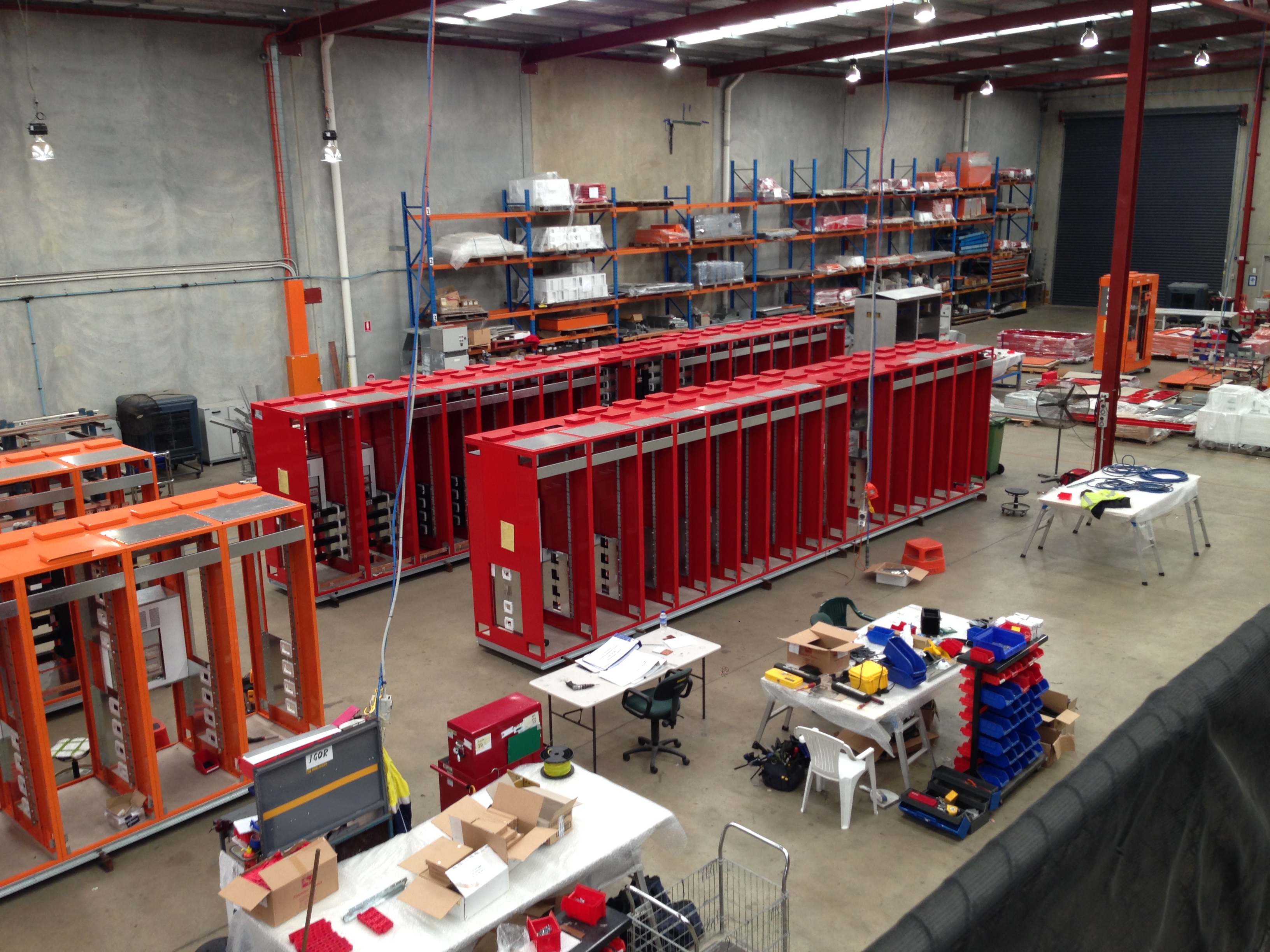
The different colour are for essential and Non-essential. The front two boards are for the Northern Substation and Plant Substation is at the back, I re-visited yester day and they are a lot further ahead looking at Factory Acceptance Tests on the 6 June and delivery on the 9 June.
The next challenge is the Corridor of Death which is slowly progressing and I am trying to get the subcontractors to utilise the model which they are contractually to do as much as possible. We have had to move one Fire Hydrant Pipe which has been in location since last October as Fredon Mechanical Services Subcontractor modelled there pipe wrong and did not even model the brackets themselves. The corridor is becoming an increasing concern and we called in the director of the main problem child subcontractor yesterday to try and resolve some design and shop floor problems. This meeting will hopefully see change and progress watch this space for an update!
To prove we do use modelling attached is an area I am working on at the moment, the interface between corridor and main service riser.
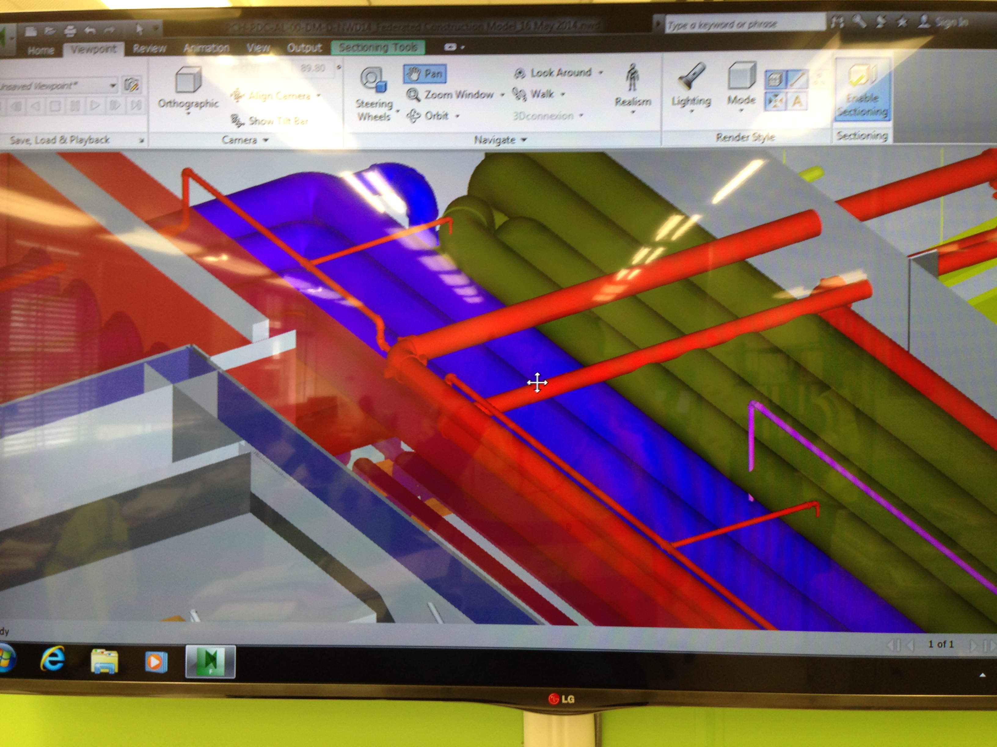
We have also started to see progress in all the Plant rooms and these should start to progress over the next few weeks……
Like for like, but not quite…
The pace of life in Aberdeen is picking up and people are actually starting to ask my opinion and give me more responsibility. In the last couple of weeks there are two jobs that have taken up a significant portion of my time; the modification of lifeboats to increase their capacity and the modification of 34 cabins on the Clair asset. Both of these projects combined will go most of the way of increasing the capacity of the platform from 120 to 154, which is the key enabler for the turnaround next summer. The cabin upgrade is going okay so I’ll only cover the lifeboats in this blog.
The Lifeboats
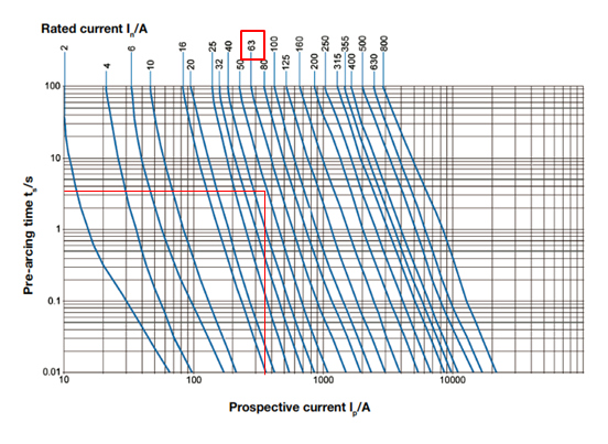
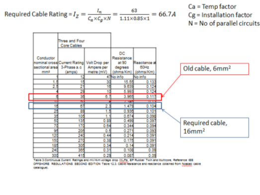
The lifeboats task has been rushed through a little bit and was supposed to be in two phases, with the first phase being like for like. Things have not turned out like that at all. Phase 1 is the recertification of a davit A frame used to lower the freefall boats into the water using a hydraulic pump unit (HPU); it is now definitely not like for like. Despite going through several levels of technical checks it turns out that the original 17kW motor has been changed for a 26.4 kW motor by the vendor and they failed to inform BP. At first it was assumed that the increase was because there must be a bigger pump in the HPU. However, this is not the case and it appears it was just the vendor standardising their HPUs. From their point of view it makes perfect business sense to standardise their units but it is criminal to not inform the client on what was supposed to be a like for like swap. As result of the change in motor there is now a problem with cabling. The current installed cabling is 6mm2 three core cable rated to 36A. Since time is very tight with when the job should go offshore the vendor is saying they cannot swap back to the 17kW motor and that the best solution is to de-rate the motor to 22 kW and change the protection device to accommodate the slightly larger motor. The calculation below is why this won’t work and why we are left with two options: 1) increase the motor and change the cabling or 2) leave the cabling and go back to a 17kW motor. What I have put below will be confirmed (probably more accurately) by WGPSN next week but this is what I think:
The old motor is rated for 17kW, with Ifl = 28 A
The new motor is 26.4 kW
In is the nominal current of the protective device.
The protective device is selected from a time – current characteristic curve where Istart up is 8 x IFL (for a motor) = 8 x 44.5 = 356A
Should the cable need to be replaced then the job may not go offshore because it will involve someone from operations risk assessing the work because there are other live cables in the pillar that feeds the HPUs. The asset may not be happy with this.
Risk Assessment
The other phases of the lifeboats are pretty much on track but there has been a great deal of risk assessment done regarding the construction because there is overboard work, scaffolding, hydraulic fluid and new technology involved. The whole process is very meticulous but occasionally there is a lapse.
When asked what was the mitigation for hydraulic fluid falling into the sea the response was to use big Norwegian thumbs to plug the hole or do it at night so nobody can see!! That sounds more like a Sapper’s approach to risk assessment.
I must stress, this was a not what was captured as the mitigation.
I will keep you up to date with this task because it is due to go offshore for the scaffolding in Jun.
Other news
I have been sampling the delights of Scottish cuisine and have come across a strange soup and a deep fried Mars bar. I’ve not tried the soup, I’ll save that for Joe Wood when he comes to visit, but the Mars bar was actually quite nice.


Cakes and Pipe Jacking
I have been rather quiet as I realised that all I seemed to be writing about was what size cast iron pipe we unexpectedly uncovered on our drainage run and what was going on with the latest in the HV cable installation saga. Well nothing has changed there we are on big old cast iron pipe number 6 in the last 10m of drainage, the client are getting excited about us damaging the HV cables and we are now extended the HV sub station slab because they put the wrong size GRP housing on top of it.
At the end of last week we had a team meeting to discuss roles and responsibilities as the Project Director has realised that they may have scrimped too much on construction management staff. We have no resident temporary works engineer or quality assurance person and these are the areas that the project are crashing and burning. At the start of the week I was looking at a promotion to being the resident engineer of the block G construction-think Ex COFFERDAM but 40m wide and 100m long with 2 stages of propping! In the initial meeting I pointed out that they might want to consider the detail of the connection of the waler to the sheet piling as they were suggesting a 1m gap to allow the construction of columns. They said not to worry about it as they would use wedges, until I pointed out that wedges spanning 1m taking vertical components of the forces probably wouldn’t work! So they went back to the drawing board and asked to move the columns in a bit!
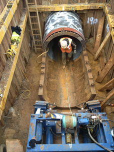
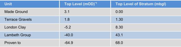
OIC Power and Drains again! But this is taking an interesting step as we are planning our pipe jacking exercise to tunnel under Battersea Park Road. In a nutshell the masterplan is to build a cofferdam to launch the pipe jacking machinery to cut a 70m tunnel approx 5m BGL to meet with an existing sewer on the other side of Battersea Park Road. watering scheme.
Pipe jacking launch shaft in top left corner tunnelling 68m with the final 30m under a raised section of the Battersea Park Road bridge: and a typical pipe jacking launch shaft:

General works:
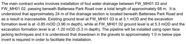
The main issue is one of John’s favourites: GROUNDWATER! In the foul drainage run we have had to sump pump a considerable amount of water flowing through the Terrace Gravels, which is also slightly tidal as we are about 300m away from the river.
![]()
The plan is to control the groundwater with a de-watering system:
Likely issues:
-Proximity and state of dilapidation of the Battersea Park Road Bridge.
-Proximity of Network Rail lines.
-Risk of settlement of bridge foundations.
-Risk of encountering unknown services or obstructions.
-BOUNDARIES/PROPERTIES-although we can’t be tunnelling through much worse than the gravels which will be pouring water in! Unless we hit an old brick pile or more of the old gas works infrastructure.
-GROUNDWATER-we are pretty much in the worst case scenario.
-CONTAMINATION-So far we have been OK with de-watering around the site so fingers crossed it can just go down the foul sewer.
Without looking at my notes they were the main points I remember from John banging his hand against the wall! No doubt I will have more to write on this over the next few weeks.
On a plus point I held a Colossal Cake Sale for Help for Heroes in the canteen and we made £220. I mentioned to our Environment/Schools/PR person that I could come in uniform and she held me to that offer. The problem was mine was all in the attic in Poole. So after a quick cycle to a friend’s house 5 miles away I squeezed myself into an ex-Army Air Corps Adjutant’s tailored(!) green kit to sell our cakes for an hour. I was overwhelmed by the generosity of some of the guys on site and the support from both the managerial staff and groundworkers. Not a bad outcome for a couple of hours work.

Fighting Fire with Fire
The last couple of weeks have been dogged with industrial action, which has resulted in the loss of around 4 days work. The dispute is centred around a change to Australian legislation governing the access of union officials to site. Previously, a union official could access any site if they deemed that there was an urgent safety issue, and demand that work cease until the issue had been resolved. This translated to a carte blanche for union officials to wreak havoc on construction programmes, and chuckle while site management frantically tried to replace a first aid box that had a broken seal, for example.
The new laws require union officials to give 24hrs notice to site management, so as to enable them to rectify the issue without having to stop work on the site. This has gone down badly with the unions who are doing their best to beat major companies (as far as I know, this is not restricted to John Holland) into flouting the law and allowing immediate access. The tactics to date have been to call 2 hour union meetings, which they are entitled to do. The clever part is that they will hold meetings for select trades at different times of day so as to ensure there are never enough of the right people on site to pour concrete.
There have been several incidents of union officials turning up on site and gaining access before John Holland staff have a chance to respond. The JH head office response has been to employ an Ex Columbian Army Commando to guard the site – hence the blog title, fighting fire with fire. Whilst he really does look the part as a visual deterrent, it would be severely frowned upon if he were to employ his ninja skills to scalp a union rep at the entrance to site. As such has been instructed to call the PM if he sees anything. His presence has also antagonised the union members; an outcome I think most of us could have foreseen.
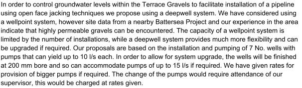
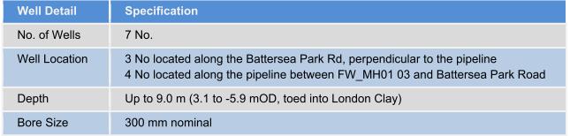
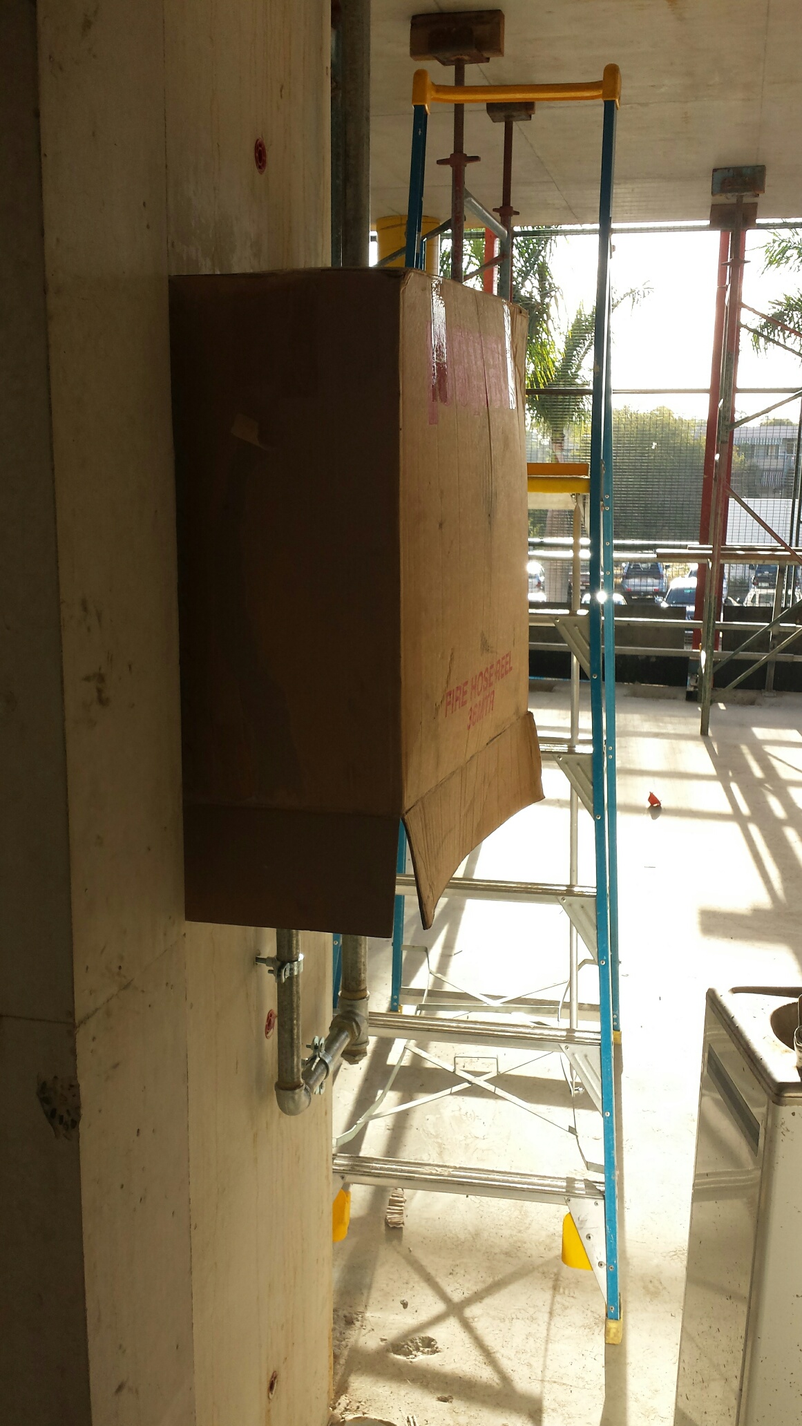
Switching subjects, I was hoping for some advice from the floor. As we are about to pour one of the level 5 slabs, the Building Code of Australia suggests that we are obliged to have a fire hydrant system and fire hose reels in place and working up to level 3. Several JH staff members are concerned with the security of the fire hose reels, particularly as we are in the middle of a Uni campus and the little scrotes have accessed site after hours on several occasions. I only need to think back to the time Steve Crosby-Jones emptied out a 30 storey tower block of students after a couple of beers at Cov Uni, to gauge the likelihood of turning up to a flooded site in the morning. This site isn’t particularly hard to access so the security of the hose reels will need to be localised. It will also need to allow easy access to use the hose if required. Does anyone have any experience / suggestions that they could share?
I have included a picture of one such fire hose reel to help you visualise the problem.
Fire Hose Reel on Level 2
From the other side
Demonstrating the current protection.
In other news, we had a work trip to see the Brisbane Broncos play the Gold Coast Titans on Friday. Those who know me will appreciate that a fair few beers were consumed, particularly as it turns out that my boss is even more of an animal than I am! The result was me doing the plank on a kerb stone whilst trying to get rid of hiccups at 3 in the morning.

The plank!
I’ve got piles…in the ground
I’ve spent a lot of my time checking and re-checking steel reinforcement schedules the past 2 weeks. I have very little confidence in the scheduler appointed by the steel makers (Onesteel), and I have picked up numerous mistakes. Some of them may be innocent, but others are obviously in hope to sneak in extra steel as they are paid by weight. Our client will only pay us based on minimum lap lengths, and have issued what they expect the schedule to be, however I have found mistakes in their schedule too (wrong diameters of bars that do not match the drawings issued to us). This made me dig deeper and it seems they are also not following the bar bending sizes in their own standards. There is also some incredibly difficult reinforcement to make work in the headstock. This has been put off for some time due to firefighting other more pressing issues, now it is crunch time. Everything is complicated due to it needing to sit in a glorified bathtub 6m up in the air (just a really big 20 tonne, 12.5m formwork bathtub). SO I’ve been trying to draw lig sets that sit inside other closed ligs (The magic trick with 2 steel rigs that click together springs to mind).
Piling progress has been painfully slow. The brand new hammers that came from Singapore have not been dropping consistently. We thought that one was fixed on the second rig (the manitowok), but then it started to blow hoses. So 3 days were lost due to replacing all the cheap Chinese hoses with high pressure ones made in Australia. Thankfully, it now seems to be working OK, so its moved to pier 3 and started on the Southern end. This is where the critical path is, and where the bridge needs to start getting built from. The casting yard is to the South of the main site and the sequence for girder casting has always started at pier 3. The work done on the North of the site was just to keep the piling rigs busy till the access track was completed. In effect buying us time.
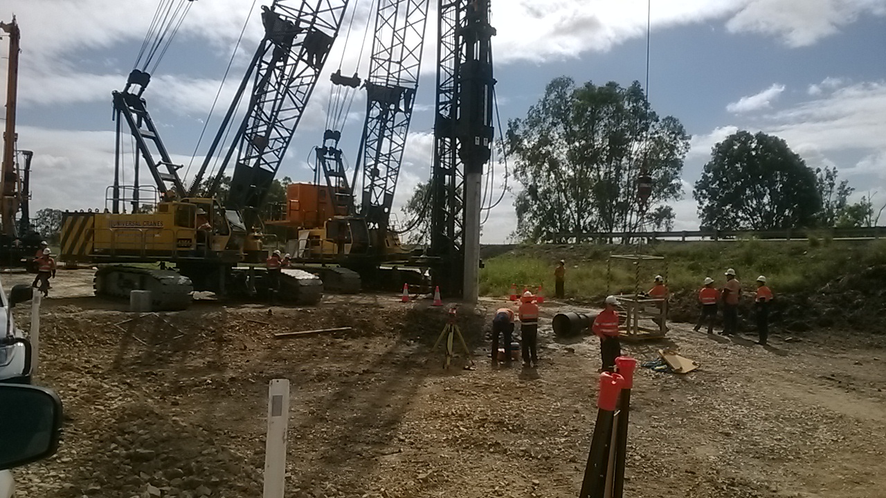
Rig 1 (the Waltman) is still suffering from inconsistent blows every 50 to 100 strikes. After 3 experts have been flown over from Singapore, all with a boxful of parts it seems to be getting better. As I type it is moving from the North to the South of the site to start working there on Monday. By my count the pilers are now 2 and a half weeks behind schedule. I’ve lost time how many iterations of my program I’ve gone through now, constantly changing the plan to meet what can be delivered by the pilers.

The 2 test piles that need to be tested with PDA were finished by rig 2 yesterday. The first one came up well with about 4000KN once it hit the weathered rock layer we were aiming for, however the second one hasn’t (Its at the opposite end of the pier). It could be that the rock layer is deeper here). I called a stop to the driving at the limit of the overdrive allowance as if we drove any deeper there would need to be a lot of remedial work done in fixing up pile to ensure sufficient splice length in the pilecap. While there are ways to deal with such an event it has not been covered or costed in the contract. As such if the client want us to go further than their design we will need to be instructed to and will cost the works accordingly. I’ve also learnt how to use the PDM machine, in the event of someone being off sick or on holiday. It’s a fairly simple bit of kit – I just need to get better at the calculation done following the data gained. And learn CAPWAP for my TMR…

Running parallel to this I’ve been finishing the beast that is the substructure methodology and AMS. This needs to cover all the risks involved with everything from breaking down the piles, excavating, formwork installation (for pilecaps, columns and headstocks), concrete pumping and then stripping the forms. This will take up a lot of my time in the coming week as we near the first pilecap excavation. Oh and the pile cropper should arrive this week, I’m sceptical as to how much time it will save us, but I will let you know in the next blog…
Oh, and the crossing across Scrubby Creek is finally finished.

