Archive
Learnings on Sustainable Drainage
Introduction
My work at Baltimore District has seen me introduced to sustainable drainage practices across the whole construction lifecycle – concept and planning phases in Phase 3, construction in Phase 2, and maintenance and retrofitting (also in Phase 3)… Okay, no proper termination/deconstruction yet… so maybe not the entire lifecycle …. but you get the point.
Because of my exposure to it and it’s relative importance in gaining planning approval for a project, I thought I’d summarise some of what I’ve learnt to see if anybody else had come across it during their attachment and possibly start a conversation about any differences to UK practices/approaches. Please note that all images are most definitely NOT my own – thanks go to mostly google, and also to the US EPA!
Sustainable drainage forms part of what the US calls environmental site design – though I haven’t experienced it on attachment. In the UK such sustainable drainage practices are also accompanied with the term SuDS (Sustainable Drainage Systems), however, in the US, the philosophy, though very similar, is called LID (Low Impact Development). As a general term, however, most engineers in the US refer to drainage, flood protection etc… as SWM – pronounced ‘swim’ (Storm Water Management).
Why do we need SWM?
In a nut-shell, development tends to reduce the ability of the ground to soak up rainfall through abstraction, a term used to cover infiltration, depression storage, and transpiration etc… This results in more surface water – or run-off. This effect is best shown in a graphic such as the one below from the US Environmental Protection Agency’s technical report on the subject:

The consequences of such increases in run-off are numerous. Water quality issues include increased levels of pollutants such as nitrogen, phosphorous, and sediment reaching downstream water bodies. It can also result in changes to such a waterbody’s temperature, damaging the health of flora or fauna. In addition to the more obvious issues of flooding through increased run-off volume, water quantity changes can result in higher peak flows and subsequent erosion or scour, as well as loss of groundwater recharge, thus lowering the water table and/or reducing the base flow of local rivers and streams.
History of SWM in Maryland
SWM has undergone a significant evolution over the last 20-30 years. The more recognisable, traditional, approach to drainage used piped systems to convey untreated water quickly to a local outfall:


This practice then morphed into ‘conventional SWM’ which used large detention basins (‘dry ponds’) with a flow control device to outfall into the receiving water in a more sustainable manner. These practices mostly focused on treating quantity, though some ponds were later designed to hold a permanent pool of water. This resulted in them becoming known as ‘retention’ basins, or ‘wet-ponds’: these retention practices were able to improve water quality, in addition to quantity, as the permanent pool of water enabled settlement of suspended solids and breakdown of heavy metals prior to the water’s discharge into the receiving water. Two pictures of a detention practice are shown below:


By the early 2000’s, modern sustainable drainage was taking shape and LID was conceived as a means of delivering the benefits of conventional SWM but through de-centralised practices, close to the source of run-off. This prevents concentration of pollutants and reduces the size requirements of individual practices, making them more easil incorporated into urban designs. These ‘Best Management Practices’ (BMPs) include practices such as rain gardens/bio-retention features, submerged gravel wetlands, and green-roofs etc…. The major improvement to conventional SWM being that LID/modern SWm promotes infiltration into the ground, thus re-establishing groundwater properties and mimicking a site’s natural hydrology despite development.
Examples
The image below shows a typical LID practice beside a car park. The gutter allows water to enter a grassed area with a concrete level spreader in the mid-distance enabling a small amount of ponding prior to overflow into a heavily vegetated bio-retention area. The grate in the near-distance provides an overflow facility which is modelled simply as a weir.

But LID is not just about saving the environment. Fort Belvoir’s hospital was fitted with a stormwater harvesting system (a LID practice) that connected the roof drains and air-conditioning condensate pipes into cisterns able to hold 160 thousand gallons of water. This water is then used for landscape irrigation, saving the hospital an estimated 1.6million gallons of water per year – this represented a significant saving in the building’s running costs!

Transition to the USACE Design Office at 2 Hopkins Plaza
With the cobwebs of Christmas and New Year finally gone (along with AER 4) I thought it was about time I wrote an update of my attachment in the USA.
As of mid-December, I was able to handover the majority of my work at the East Campus in Fort Meade to a young and overly energetic intern. With the majority of the project complete and the main effort shifted to the architectural team’s handover of internal rooms and the mechanical team’s underfloor air distribution (UFAD) testing and commissioning, I almost felt a little sorry for the guy – arriving with so little civil works left to complete. From me, he inherited responsibility for:
- Processing and distributing the daily submittals from the contractor,
- Supervising the production of as-built data for the site’s sustainable storm water management (SWM) systems.
- Supervising the placement of internal roads (a combination of pervious, and impervious concrete), and
- Supervising the contractor’s application of erosion and sediment controls on behalf of the State’s department of the environment.
Surprisingly, he seemed a little overwhelmed and concerned that some of the work allowed him to make decisions and issue site instructions. I hadn’t realised how accustomed the army and such a short time spent on Phase 2 had made me to making decisions and accepting responsibility. In his defence, I suppose he hadn’t even been qualified for a year and speaking to him later, it became apparent that USACE severely warns them against obligating the government to anything not already in a contract (for those just finishing up on Phase 1, remember this and don’t be overly critical of yourself when it comes to judging attribute competences).
Closer to the present, January in Baltimore has been an intense combination of very, very, very cold weather and also my re-introduction to technical engineering. After a full 8 months of performing QA of “horizontal construction” (drainage and grading, pavements and slab-on-grade with a little bit of footing work), I have commenced Phase 3 by assuming a design engineer role in Baltimore City. From now until the end of June, the intent is to work within the USACE Site Development Section performing a broad range of infrastructure and site design tasks. A small hierarchy made for AER4 showing my location within what is effectively USACE’s Baltimore design office is shown below:
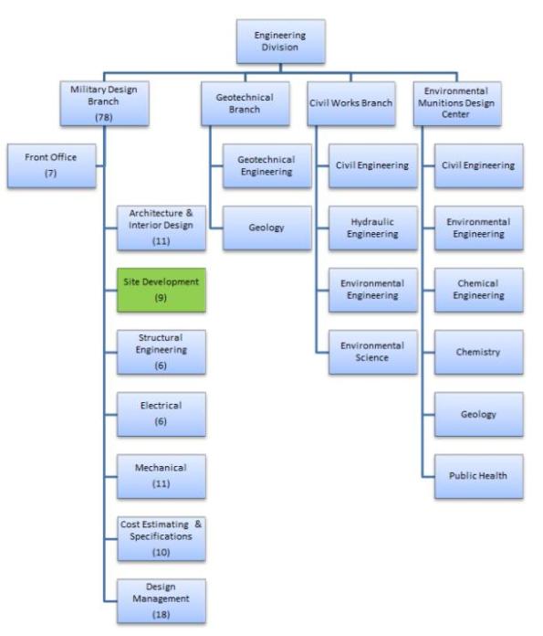
The parent organisation of the site development section is the Military Design Branch. These approx. 80 personnel design and supervise the construction of DoD facilities across an area of responsibility approximately similar in size to England and Wales. This work includes “in-house” design for DoD organisations and the technical review of in-progress or completed Architect/Engineer designs by third parties.
My main role includes a number of small tasks that essentially see me designing sustainable drainage solutions for DoD installations. The scale varies from designing systems to manage surface water volumes from design storms (normally the 1 in 2 and the 1 in 100 year storms) to designing retrofits that ensure pollutant loads such as Nitrogen, Phosphorous, and total suspended solids are reduced in the “first flush” of 1.0 inches of rainfall.
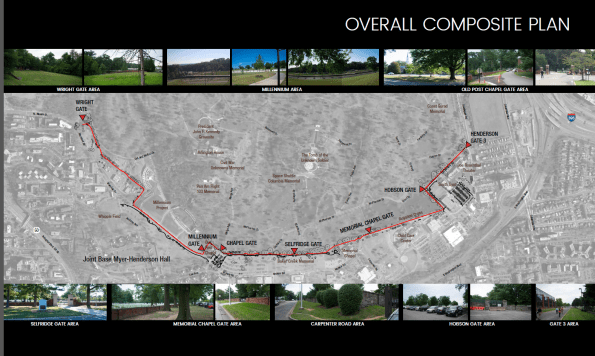
I will also soon be designing stormwater management aspects of a 2km perimeter fence that is going to be installed in Ft Myers, not far from DC and the Pentagon. Strangely for the US military, a large section of the perimeter since the late 19th century has been a 4-ft high stone wall. A number of recent incidents have occurred involving French tourists getting lost in the neighbouring Arlington National Cemetary and ‘hopping the wall’ to get to what they think is a nearby strip-mall. Unsurprisingly, the DoD has decided it may be time to increase the level of security. In addition to designing the profile and construction details of the fence plus integrated cameras etc… the project also requires consideration of bisecting drainage channels, the construction of a new car park and creation of additional SWM to account for the increase in impervious surface areas.
As we’re still waiting for the client to decide on the contract vehicle for this work, USACE and I are still a little unsure on the level of design work required but we hope to get an answer fairly soon. Until then, here are some unclassified graphics pilfered (with permission) from the department’s project folder (yes, that is a design engineer’s attempt at doing before and after concept work using photo-shop):


Damage to buried pipelines
Whilst enjoying a Friday morning lull in tempo, I thought I’d produce a quick post updating everyone on a small portion of my work on the Joint Operations Centre (JOC) Project; a part of the wider East Campus program.
Work thus far has been varied with business as usual mostly focused on construction contract administration, quality control management, and project engineering. Additionally, the project’s lead engineer often gives me additional tasks which can almost be viewed as projects. The latter mostly concern issues on site that need a combination of both project management and technical understanding to resolve. As an example, one of the first tasks given to me concerned cracked valves in one of the underground pipe networks, which will be the topic of this blog post:
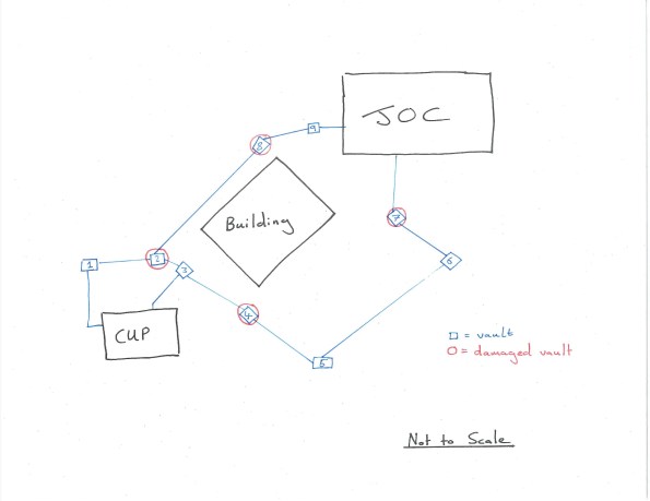
The majority of the JOC’s cooling is performed by chilling water in a separate building, the central utility plant (CUP). Chilled water is pumped from this plant to the JOC, where it is warmed at heat exchangers before returning to the CUP to repeat the cycle. The path between CUP and JOC is interspersed with mechanical vaults that allow maintenance and access to a number of valves on the underground pipe network (See hand sketch below – the blue line indicates the pipeline and includes both supply and return pipes; note the redundancy with two paths). Unfortunately, a number of valves within these vaults became damaged with large cracks appearing in the fittings. Testing of the valves confirmed the damage was to be caused by flaws in the design or fabrication of the valves. I was tasked with leading the root cause analysis and resolution of the issue.
Surveys of the damage suggested the cause lay in excessive settlement of the pipes between several mechanical vaults. By modelling the pipes as strip foundations, I was able to use Burland and Burbidge’s method to produce a ‘fag-packet’ calculation of expected settlement that corroborated this hypothesis (survey data indicated actual settlement almost 3x greater than predicted).
I was then responsible for co-ordinating numerous meetings between contractor, client, the designer of record and ourselves (USACE are the client’s representative) in order to agree a path forward. As you can imagine, nobody admitted fault and neither was anybody prepared to spend money to prove where fault actually lay. Stuck in a catch-22 situation, I was able to persuade the general contractor, Hensel Phelps (HP) into hiring a geotechnical engineer to investigate the issue. I was also able to secure financial authorization to get the designer (AECOM) to evaluate the results of my own investigations and provide recommendations. This was to also include copies of the designer’s original work, confirming the expected settlement of the pipe under assumed loading. This report, after a number of returns due to missing information, finally arrived yesterday. AECOM’s design used the modified Iowa formula – a well-recognized method of calculating displacement in laterally loaded “flexible” pipes (I must admit, one of the surprising revelations during my analysis was the fact such large steel pipes are considered flexible). The difference between using my Burland and Burbidge method and the modified Iowa formula was my results suggesting 50% more settlement (3/8 inch compared to ¼ inch). However, this may have also been caused by AECOM’s grillage analysis and subsequent live loading on the pipe being slightly less than my own.
On site, HP, has already completed replacement of damaged pipe sections. They have also performed additional remedial work within the vaults by unbolting undamaged connections, allowing free ends to deflect and reconnecting with specially fabricated ‘offsets’. On the basis that the soil is coarse grained (so long term settlement is less of a concern) and the stresses from settlement have been released through the disconnection program, it is “hoped” that the issue has therefore been resolved.
Presently, the plan is to attach strain gages to the newly connected sections and monitor for future settlement; my work to confirm what happens (and who pays) if the strain goes beyond the agreed threshold continues. The contractor is only liable for damages and the costs of repair and replacement for a year after final acceptance – after which, the costs sits with the government who would then need to prove fault and take legal action to cover damages from either the contractor or designer.
The whole experience has taught me a lot about the contractual relationships within both construction and also large government projects. It’s also developed my management skills in terms of co-ordinating multi-disciplinary and stakeholder meetings (in this instance mostly mechanical engineers are involved as it concerns their feature of work, but I’m also getting a lot of exposure to electrical and commissioning engineers in another of my roles).
Finally, I’ve noticed that I’m far more understanding of the general contractor’s stance during periods of conflict compared to USACE management, who are often very untrusting; I put this down to my relative independence compared to the rest of the team here but I suppose it could also be a result of something personal, cultural, or my military background. Has anybody else observed something similar or different on their projects?
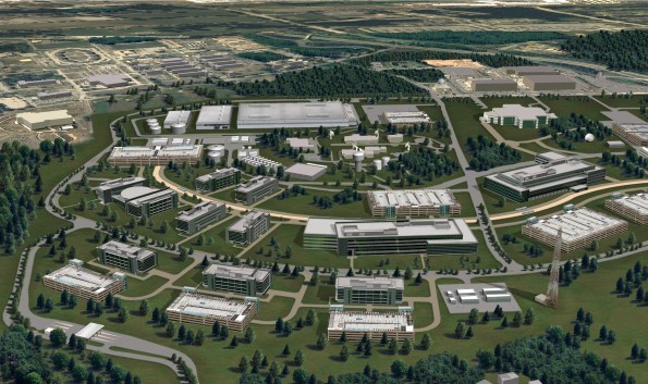
Finally, a teaser for anybody on phase 1 currently considering the USA as your attachment location. the rendering below shows the initial architectural concept for the East Campus program (It’s one of the few images of work that are releasable – The JOC and its large rounded roof is on the far left of the picture). There will be work here for at least another decade with multiple opportunities to cover several projects simultaneously, all at different stages of construction. If you’re interested and would like to know more (both civil and E&M), just get in touch!