Archive
Grasscrete – Paving the way to a sustainable future?
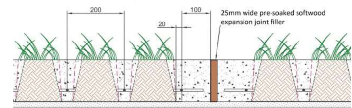
Recently, whilst working on a small access road I was introduced to what I thought was a novel, sustainable and simple paving solution – Grasscrete. After a cursory Google search, it transpires that it has been in existence since the 1970s- and indeed some of these uses are still standing. So what is it? And has anyone come across this before?
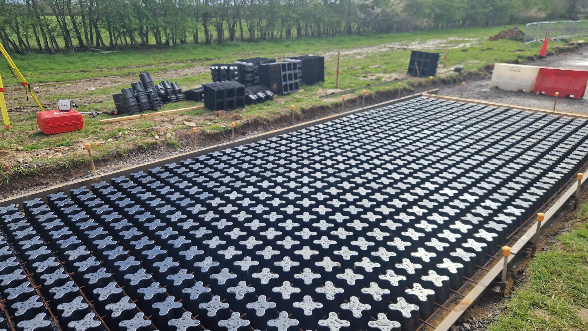
Simply put, it is a permeable pavement made up of recycled plastic formers and some steel mesh. Once installed some configurations claim to be able to carry weights of ~40T and use approximately 50% less concrete, with no need for active drainage. Relatively simple to assemble one can see why it would be attractive to a customer such as the MoD:
Less concrete means less water, less cement and ultimately less logistics – usually a major consideration when operating in austere environments.
Resistant to differential settlement – Acting as a monolithic slab, loads are uniformly distributed.
With much less run-off, grasscrete is more resistant to storms and stormwater run-off, not requiring active drainage.
Much more durable for expedient roadways and even HLSs for expeditionary theatre entry.
So what are the downsides?
More expensive than standard RC slabs
Plastic formers can be fragile – especially if left in hot temperatures or direct sun.
Lateral forces, especially from heavier vehicles braking/accelerating, may crush the narrower sections of the voids.
Rebar is at more risk from corrosion, minimum cover – especially if voids are filled with soil rather than quick draining gravel.
Whilst it may seem that I’m taking a commission from Grasscrete (c), perhaps Grasscrete/permeable pavements are something the Corps could look at? Whilst not structural and worth a TMR or two on its feasibility, I thought I’d sow the seed on this one…
I’d be keen to see if anyone else out there has seen this before and perhaps why its not been rolled out more often, especially for less trafficked areas/access roads etc. Without getting too far into the weeds…
Preloading your backprops for maximum load distribution
Read time: 10 mins.
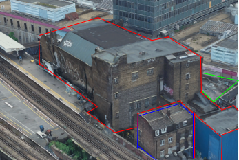
One of my first tasks on Phase 3 has been to develop a temporary works solution to support the demolition of the roof (RF1) and 3 levels (L01, L02 and L03) of suspended concrete slabs of the Coronet Theatre in Elephant and Castle. In order to demolish these elements, an 8 tonne excavator will be lifted onto L03 and break RF1; once completed the props on L02 will be removed and the plant will be lifted to L02 so that L03 can be demolished and so on.

Specifically, I have designed a back propping system to transfer demolition loads (plant and demolition debris) from suspended concrete slabs to the ground. Back propping is required because a cursory check tells us that the concrete slabs were designed for imposed loads much lower than those imposed by an 8 tonne excavator and up to 0.5m of demolition debris.
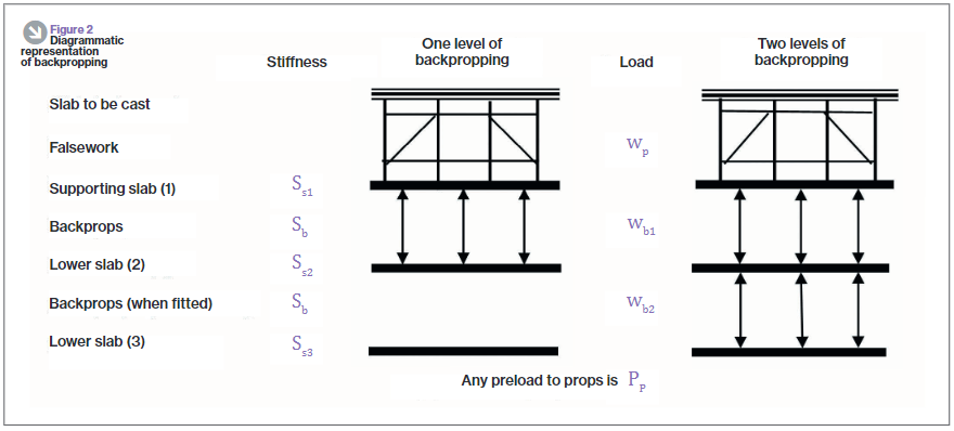
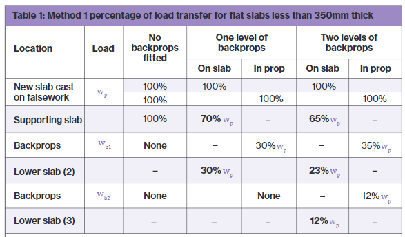
As you can see from the diagram, the loads from the working platform will be transferred directly to the ground, however, in the development of this solution I considered transferring the loads to L02 and L01 only to save the Client the use of the costly Titan props used on the ground floor. In doing this I used the principles taught to us in applied structures (by JAM I think?) that were summarised by Pallett (2016) typically used when designing falsework, see diagram below.
Pallett tells us that with two levels of back propping, I could distribute 65% of the demolition works loads onto L03, 23% to L02 and 12% to L01. With just one level of back-propping this distribution would be 70% to L03 and 30% to L02.
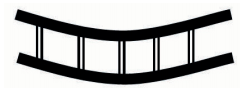
One might expect that with the use of a rigid prop, deflection in the top slab would equal deflection in the supporting slab as shown in the diagram below. If this was true then the load on the top slab would be split equally between the top and supported slab, 50% of the load to each. In essence, the two slabs become one member with the slabs acting as flanges and the props acting as webs. So why does Pallett tell us that the loads would be distributed 70/30, not 50/50?
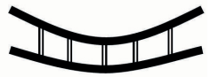
The answer is because the props too act elastically and shorten when exerted to the axial load as required by d=PL/AE. If the member can’t shorten, then the load can’t be transferred. Instead, the interaction between the slabs and props looks much more like that in the diagram below. There it can be seen that the deflection for the top slab is greater than that of the supporting slab.
Preload your backprops!
Unfortunately it was still assessed that even 65% of the load imposed by the demolition works would be too great for the suspended slabs and so I looked for other solutions, determined not to use the expensive lower level Titan props. I had seen that Pallett released a further article in TheStructuralEngineer in 2017 that suggested that backprops could be pre-loaded, an interesting concept that I thought I’d look into.
Think about how you install a prop, typically you stand it between the supporting and supported slab and begin to twist the collar, extending the prop until it is firmly wedged in place. Well what would happen if you kept twisting the collar, perhaps using a sledge hammer or using a long spanner as a lever? The answer is that the top slab would start to hog and the bottom slab would begin to sag. It turns out that by doing this we can actually achieve the conditions so that the load can be shared equally between slabs, 50% each for a 2 slab system or 33% each to a 3 slab system as is the case with my problem in Elephant and Castle.
How to design back-propping
It’s all very well knowing that by exerting a load on the supporting and supported slab by preloading your backprops you can distribute loads imposed on the supported slab equally, but how can this be designed? It can be designed by the basic application of PL/AE.
Take the following example:
E: Prop material stiffness = 69 GPa. The Youngs modulus value for aluminum.
A: Prop section area of material = 0.00259m2. Taken from manufacturer’s technical literature.
L: Length of prop = 2.982m (distance between slabs).
P/d: The force per mm extension, kN/mm.
and rearrange the equation so that P/d = AE/L. We can then work out that for every 1mm the prop is extended, it exerts a force of 60kN. If we also know from the technical literature that one thread (turn) equates to an increase in prop length of 2mm, the instruction to site in order to exert 30kN to the supporting and supported slab each (60kN total), would be to give the collar half a turn. Tests carried out as part of the European Concrete Building Project (ECBP) found that by using this method with a prop system, you could practically apply an upwards UDL of 0.5kN/m2 on the bottom of a slab.
Of course, if using this method to equally distribute loads there are a few things that need checking:
- Has the supported slab got sufficient reinforcement to tolerate the hogging due to the applied upwards force; a typical concrete slab would have maximum sagging and minimal hogging reinforcement at mid-span.
- Are the loads acting on the supporting slab (self weight, load imposed by preloading props, shared load from supported slab, other imposed loads) within the capacity of the slab.
- As the axial force in your props increases so does the likelihood that they will buckle, they might need restraining with ledger frames.
The ECBP found that this method was difficult to implement with thin slabs because of their flexible nature leading to the tendency to transfer load between adjacent props as one is tightened up.
In all there’s nothing ground breaking here but a bit of applied engineering to distribute that little bit more load between your slabs, it might just make the difference.
References:
- Temporary Works Toolkit. Part 4: An introduction to backpropping flat slabs. Pallett, TheStructuralEngineer (2016)
- Temporary Works Toolkit. Part 6: Backpropping flat slabs. Pallett, TheStructuralEngineer (2017)
