Archive
Assessing Plant Loading on Concrete Slabs
For the last couple of weeks I’ve been working for a Client (Keltbray) who was awarded the work to re-purpose a 7-storey office building at St. Pauls, London. As part of the structure re-purpose, Keltbray are required to conduct a full soft-strip and a partial demolition of certain structural slabs, beams and walls.
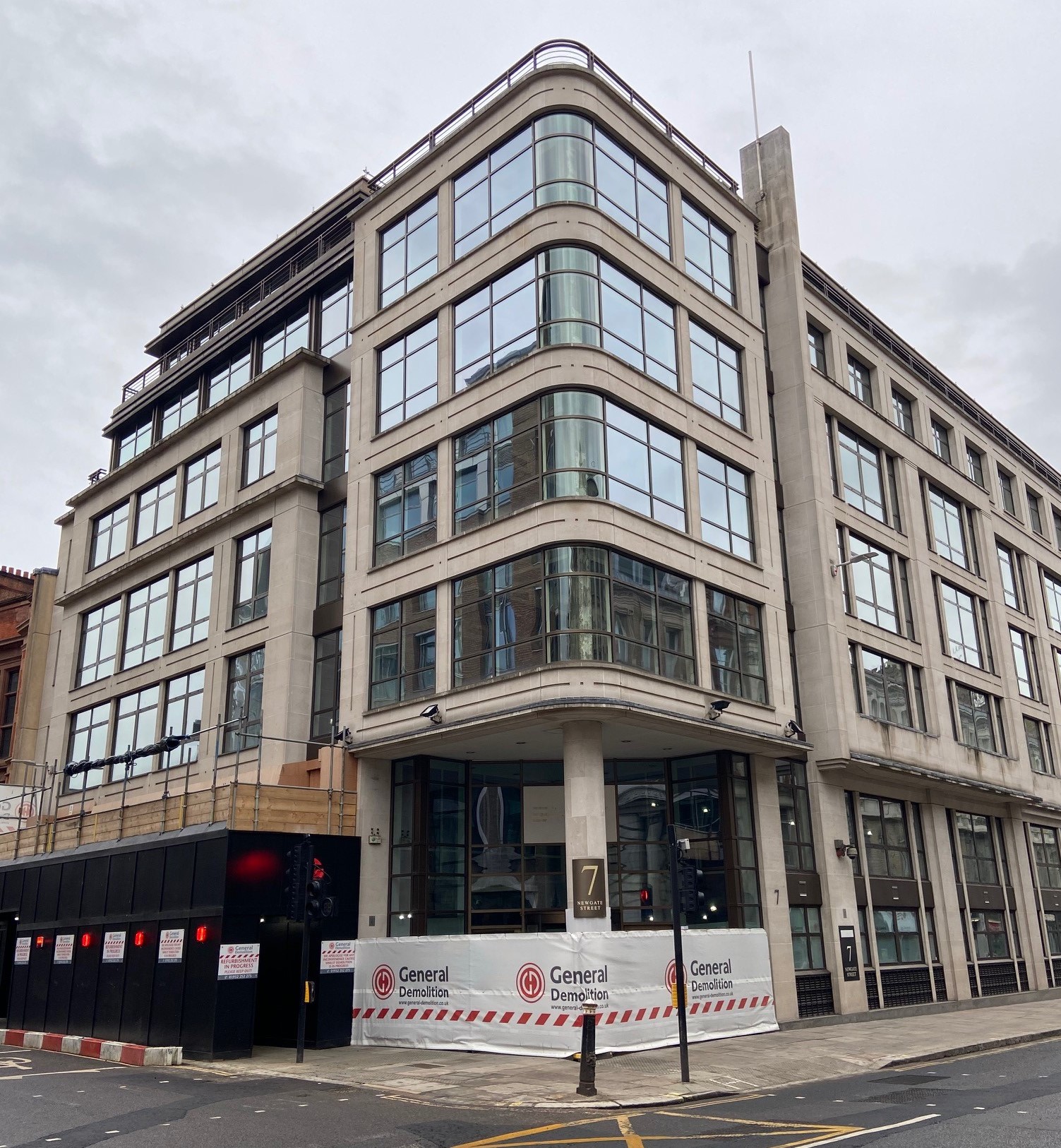
One of the design briefs issued to me was to confirm that the structural slabs on each floor had the capacity to support various plant including a Bobcat T450 compact track loader (see below). The T450 has an operating weight of 2,961kg, a track length of 1.28m and a track width of 0.3m.

In this post i’m going to summarise some of the quirks associated with plant loading and their load cases, and summarise some of the different methods I used to assess an in-situ slab.
Check 1 – Structure Design Loads
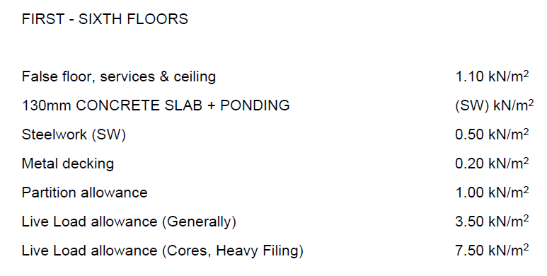
Fortunately the Client was able to provide me with a demolition specification document which defined the working loads for which the structure was designed originally. If these are available, of course the simplest check to do is to see if the pressure exerted by the plant is less than the allowable loads as specified in the design load. In this instance I knew that after the soft-strip all false floors, services, ceilings, partitions and any other variable and quasi-permanent loads would have been removed. This consequently left me with 5.6kN/m2 slab capacity, unfortunately a very crude calculation showed that the load exerted by the plant would result in a pressure of nearly 40kN/m2.
Note – When using this method there is no requirement to factor the plant loads.
Check 2 – Check Max Bending and Shear
If check 1 fails, as it did for me, the next consideration should be that whilst the plant exerts a much greater pressure than the design loads, it is only exerted over a small area, compared to the design loading which could be exerted over the whole slab span. To do this I needed to consider the various loading combinations of the plant.
Step 1 – Establish loading configurations of plant
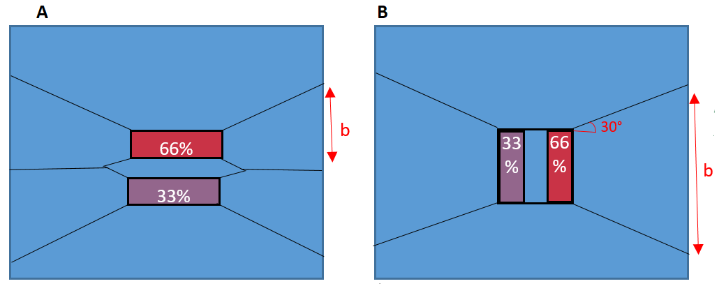
Tim Lohmann, Director at WHP, wrote an article in the ICE Forensic Engineering Journal explaining that the moments experienced by plant (through their typical construction activity) can cause an imbalance of loading. When these moments are perpendicular to the direction of the tracks, it can lead to up to 66% of the load being transferred through a single track. When the moments are in the same axis as the track direction, they can lead to a 33% reduction of effective track bearing area to due to the Meyerhof principles.
These principles are demonstrated in the figure below, for more information the article can be read by clicking ‘download’ below.
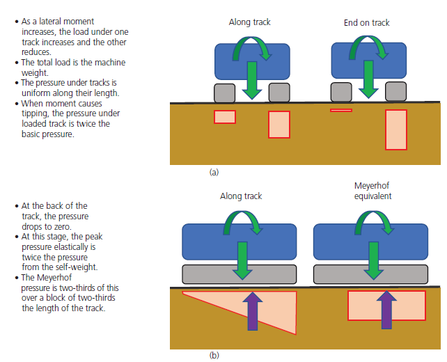
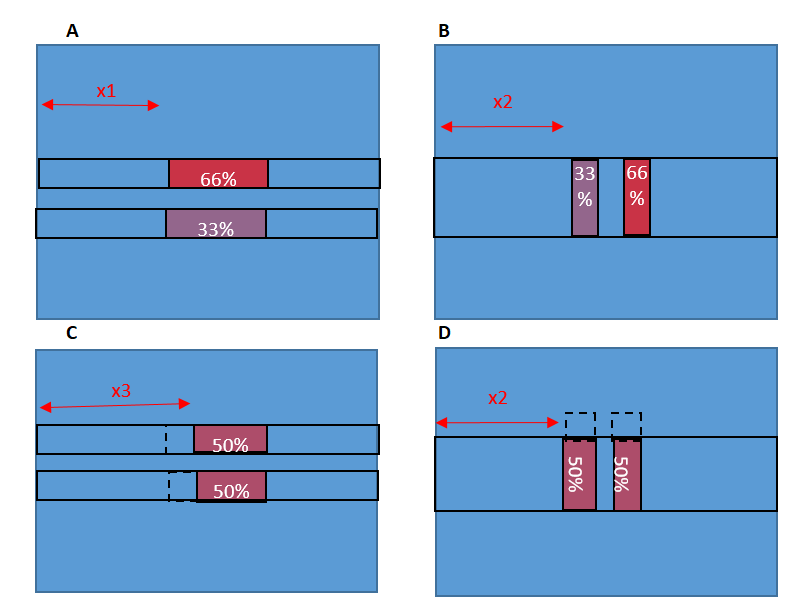
Because the slab I was assessing was one-way spanning, I had to consider both cases (a) and (b) above for the plant sat parallel and perpendicular to the slab direction. The four cases considered are in the diagram below. To find the max bending moment, the plant has been modelled at the mid span of the slab.
Step 2 – Calculate max SF and BM due to plant loading
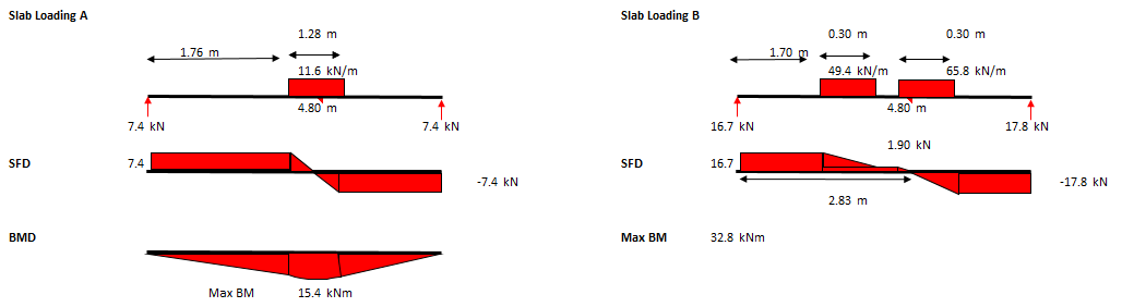
The maximum bending moment and shear should then be calculated for each of the 4 combinations shown above. The SFD and BMD for cases (A) and (B) above are below.
Note – Ensure that the span you select is the maximum slab span anywhere on the floor you are assessing, as this is where the maximum BM will develop.
Note – The loading due to the plant should still not be factored.
Step 3 – Calculate Max SF and BM due to slab design loading
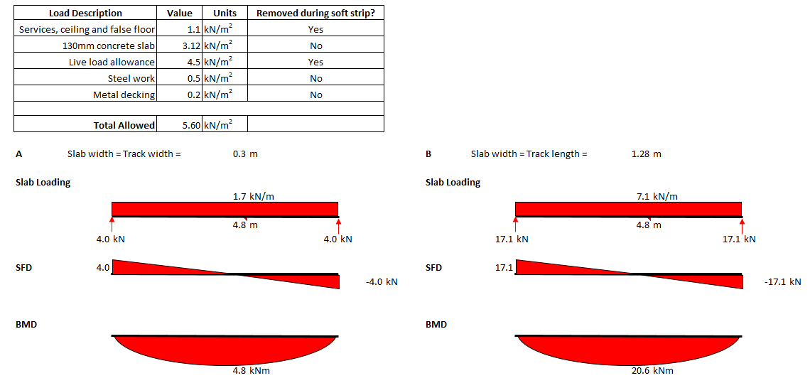
Using the design loads for the slab (5.6kN/m2 as determined from demo spec), the maximum SF and BM that the slab has been designed to withstand can be calculated. Below are the max SF and BM for cases (A) and (B) above. The 5.6kN/m2 pressure has been multiplied by the width of the one-way spanning slab being assessed which is a track width for case (A) and a track length for case (B).
When compared to the max BM due to the plant in step 2, you can see that the SF or BM due to the design loads is significantly less than the SF and BM developed by the plant loading. If, when checked, it is found that these BM and SF are greater than those developed due to the plant, the assessor could safely say that the slab does have capacity for the plant.
Check 3 – Slab Section Analysis
If check 2 failed then the checker should check the section properties of the slab for capacity against the max SF and BM developed in the slab due to the combination of plant loading, slab self-weight and any other loads that may not be removed during the soft strip. Whilst the plant is positioned at the mid-span, the max BM will be at the mid-span.
Note – For this check the loads should be factored.
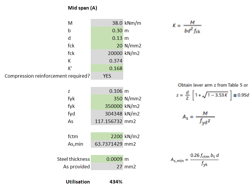
For my example, I calculated that for loading case (A) the max BM was 38kNm and then used EC2 to determine the steel reinforcement required. Because the slabs I was analysing were 130mm deep composite (steel deck) slabs, the 0.9mm thickness of the steel deck can be assumed to work as the tensile reinforcement.
Note – The yield stress of steel deck is unlikely to be the same as that for structural rebar (500N/mm2). I found it ranged between 280-350N/mm2 but check the manufacturer’s technical literature. The assessor should also check that the steel deck allows for sufficient bonding with the concrete for it to act compositely (normally achieved with dimples in the steel and shear studs).
A fundamental part of the check requires the slab (section) width to be considered. I noticed that when I considered load cases (A) and (C), where the slab width = track width = 0.3m, the section did not have sufficient bending resistance (failed by 334%) – see calculations below.
Check 4 – Assume load dissipates at 30 degrees
The assumption I had made from the very beginning was that, because the slab was one-way spanning, it was only the width of slab that was being loaded that could provide any resistance to bending/shear. However, according to BS8110-1, similarly to the way a concrete beam without shear links will normally fail on a plane inclined at an angle of about 30° to the horizontal, it can also be assumed that even a one-way spanning slab will utilise the strength of the surrounding slab, at an angle of 30 degrees.
Using the principle described above, a new b (slab width) can be determined which can be inputted into the same section analysis conducted in Check 3. For load case (A), I calculated that at the slab support, the slab width was now 1.72m. This new slab width allowed me to calculate that the slab did have sufficient tensile steel.

Note – The issue with utilising this 30 degree spread is that the same checks should be conducted with the plant moved from mid-span to close to the supports. As the plant is placed closer to the support, the max BM will reduce but so will the effective width of the slab (due to the 30 degree spread).
Additional checks required
- Whilst max bending occurs whilst the plant is at the mid-span, max SF occurs when the plant is closest to the slab support, this should be modelled to check shear capacity and punching shear.
- If check 4 (the 30 degree spread) is conducted, checks should be conducted for all 4 load combinations with both the plant at mid-span and close to the supports.
- If the slab is continuous, checks for tensile reinforcement in the top of the slab to deal with hogging should also be conducted.
Summary
When working for a design consultancy, the efficiency with which we carry out these kind of checks is what makes the company the most money. This post demonstrates a hierarchy of checks that can be used, from most basic to more complex until I reached the stage where my check passed. Whilst the labour intensive check 4 gives the highest chance of a check passing, a quick check might show that the simpler checks 1 or 2 might also pass (and take a fraction of the time to complete).
If even check 4 fails then FE analysis may be required. Otherwise it might be time to tell the contractor that they either need to downsize their plant, or back-prop their slabs.
Preloading your backprops for maximum load distribution
Read time: 10 mins.
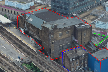
One of my first tasks on Phase 3 has been to develop a temporary works solution to support the demolition of the roof (RF1) and 3 levels (L01, L02 and L03) of suspended concrete slabs of the Coronet Theatre in Elephant and Castle. In order to demolish these elements, an 8 tonne excavator will be lifted onto L03 and break RF1; once completed the props on L02 will be removed and the plant will be lifted to L02 so that L03 can be demolished and so on.

Specifically, I have designed a back propping system to transfer demolition loads (plant and demolition debris) from suspended concrete slabs to the ground. Back propping is required because a cursory check tells us that the concrete slabs were designed for imposed loads much lower than those imposed by an 8 tonne excavator and up to 0.5m of demolition debris.
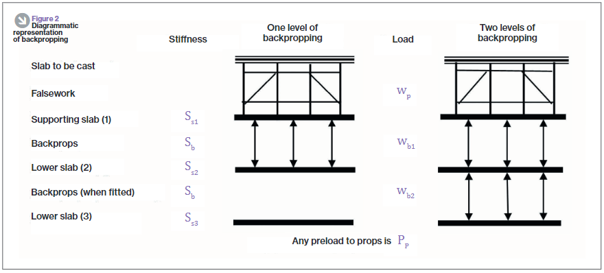
As you can see from the diagram, the loads from the working platform will be transferred directly to the ground, however, in the development of this solution I considered transferring the loads to L02 and L01 only to save the Client the use of the costly Titan props used on the ground floor. In doing this I used the principles taught to us in applied structures (by JAM I think?) that were summarised by Pallett (2016) typically used when designing falsework, see diagram below.
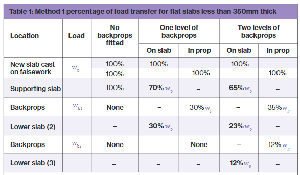
Pallett tells us that with two levels of back propping, I could distribute 65% of the demolition works loads onto L03, 23% to L02 and 12% to L01. With just one level of back-propping this distribution would be 70% to L03 and 30% to L02.
One might expect that with the use of a rigid prop, deflection in the top slab would equal deflection in the supporting slab as shown in the diagram below. If this was true then the load on the top slab would be split equally between the top and supported slab, 50% of the load to each. In essence, the two slabs become one member with the slabs acting as flanges and the props acting as webs. So why does Pallett tell us that the loads would be distributed 70/30, not 50/50?

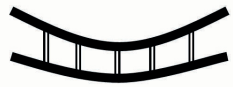
The answer is because the props too act elastically and shorten when exerted to the axial load as required by d=PL/AE. If the member can’t shorten, then the load can’t be transferred. Instead, the interaction between the slabs and props looks much more like that in the diagram below. There it can be seen that the deflection for the top slab is greater than that of the supporting slab.
Preload your backprops!
Unfortunately it was still assessed that even 65% of the load imposed by the demolition works would be too great for the suspended slabs and so I looked for other solutions, determined not to use the expensive lower level Titan props. I had seen that Pallett released a further article in TheStructuralEngineer in 2017 that suggested that backprops could be pre-loaded, an interesting concept that I thought I’d look into.
Think about how you install a prop, typically you stand it between the supporting and supported slab and begin to twist the collar, extending the prop until it is firmly wedged in place. Well what would happen if you kept twisting the collar, perhaps using a sledge hammer or using a long spanner as a lever? The answer is that the top slab would start to hog and the bottom slab would begin to sag. It turns out that by doing this we can actually achieve the conditions so that the load can be shared equally between slabs, 50% each for a 2 slab system or 33% each to a 3 slab system as is the case with my problem in Elephant and Castle.
How to design back-propping
It’s all very well knowing that by exerting a load on the supporting and supported slab by preloading your backprops you can distribute loads imposed on the supported slab equally, but how can this be designed? It can be designed by the basic application of PL/AE.
Take the following example:
E: Prop material stiffness = 69 GPa. The Youngs modulus value for aluminum.
A: Prop section area of material = 0.00259m2. Taken from manufacturer’s technical literature.
L: Length of prop = 2.982m (distance between slabs).
P/d: The force per mm extension, kN/mm.
and rearrange the equation so that P/d = AE/L. We can then work out that for every 1mm the prop is extended, it exerts a force of 60kN. If we also know from the technical literature that one thread (turn) equates to an increase in prop length of 2mm, the instruction to site in order to exert 30kN to the supporting and supported slab each (60kN total), would be to give the collar half a turn. Tests carried out as part of the European Concrete Building Project (ECBP) found that by using this method with a prop system, you could practically apply an upwards UDL of 0.5kN/m2 on the bottom of a slab.
Of course, if using this method to equally distribute loads there are a few things that need checking:
- Has the supported slab got sufficient reinforcement to tolerate the hogging due to the applied upwards force; a typical concrete slab would have maximum sagging and minimal hogging reinforcement at mid-span.
- Are the loads acting on the supporting slab (self weight, load imposed by preloading props, shared load from supported slab, other imposed loads) within the capacity of the slab.
- As the axial force in your props increases so does the likelihood that they will buckle, they might need restraining with ledger frames.
The ECBP found that this method was difficult to implement with thin slabs because of their flexible nature leading to the tendency to transfer load between adjacent props as one is tightened up.
In all there’s nothing ground breaking here but a bit of applied engineering to distribute that little bit more load between your slabs, it might just make the difference.
References:
- Temporary Works Toolkit. Part 4: An introduction to backpropping flat slabs. Pallett, TheStructuralEngineer (2016)
- Temporary Works Toolkit. Part 6: Backpropping flat slabs. Pallett, TheStructuralEngineer (2017)
Some demolition gratification!
So a few weeks ago we had a drone on site to film the progress so far. This is a client directed activity, but something we had to make allowance for on site.
You can probably guess that some of this may not be 100% as per the RAMS.
The tallest of the excavators, an HITACHI Ultra-high reach excavator, is the plant we are having issues with over the tunnels.
Points of interest:
0:12 – The majority of the buildings in this shot will eventually be demolished (except very top left)
0:23 – Ground dust suppression cannon
0:52 – Plant mounted dust suppression cannon
1:25 – Red hose feeding dust suppression cannon (these are quite exposed and often tracked by the plant)
1:44 – Some of the “off-site” works can be seen here, road upgrades and reallignment as part of the development
1:55 – The New Library can be seen here – another Carillion Project which helped them secure this project. (You can also see the Hyatt, the mirrored building, which Andy Bayley has a good story about)
2:10 – This highlights how constrained the site is and why the dust suppression is so important – there is a dedicated liaison manager who keeps all the stakeholders happy
2:35 – The white-roofed, red brick building is currently the site office – although this is going to be demolished
2:45 – The building on the left is the Birmingham Conservertoire (concerts and stuff) and is still in use – more steakholder management.
