Archive
M25 Junction 10/ A3 Wisley Interchange Upgrade Project
I have recently started phase 2 of the PET course working as part of the earthworks team in Balfour Beatty who are delivering the M25 J10/A3 Wisley interchange upgrade. The project includes the widening of the A3, free flowing left hand turns at every corner, the widening of the existing interchange roundabout, an 8 mile long non-motorised user road and 8 new bridges. There is also an increase in the road furniture and a number of re-wilding projects to offset the impact of the removal of green space along the M25 and A3. A brief overview of the project is below.
Client: National Highways (formerly Highways England)
Contractor: JV between Balfour Beatty and Atkins
Budget: £317 million
Project Start: Summer 2022
Estimated Finish: Summer 2025
Website: M25 junction 10 – National Highways
The earthworks team is responsible for cut/fill, sub-base and temporary working platforms across the whole project. The cut/fill is occurring around sheet piling operations to remove excess material, after existing bridges have been demolished and back filling behind new bridge abutments. The temporary working platforms are used primarily for sheet piling operations, CFA installation and self-propelled modular transport (SPMT) bridge construction. The construction of the platforms to enable these operations is my primary focus at the moment. Some of the temporary working platforms will be used for enabling horizontal drilling operations for services, something that will become a blog post in the near future. Below is a selection of photos of my time on site so far:
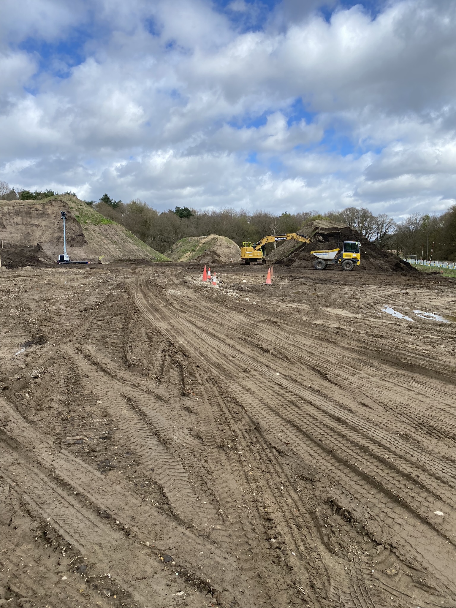

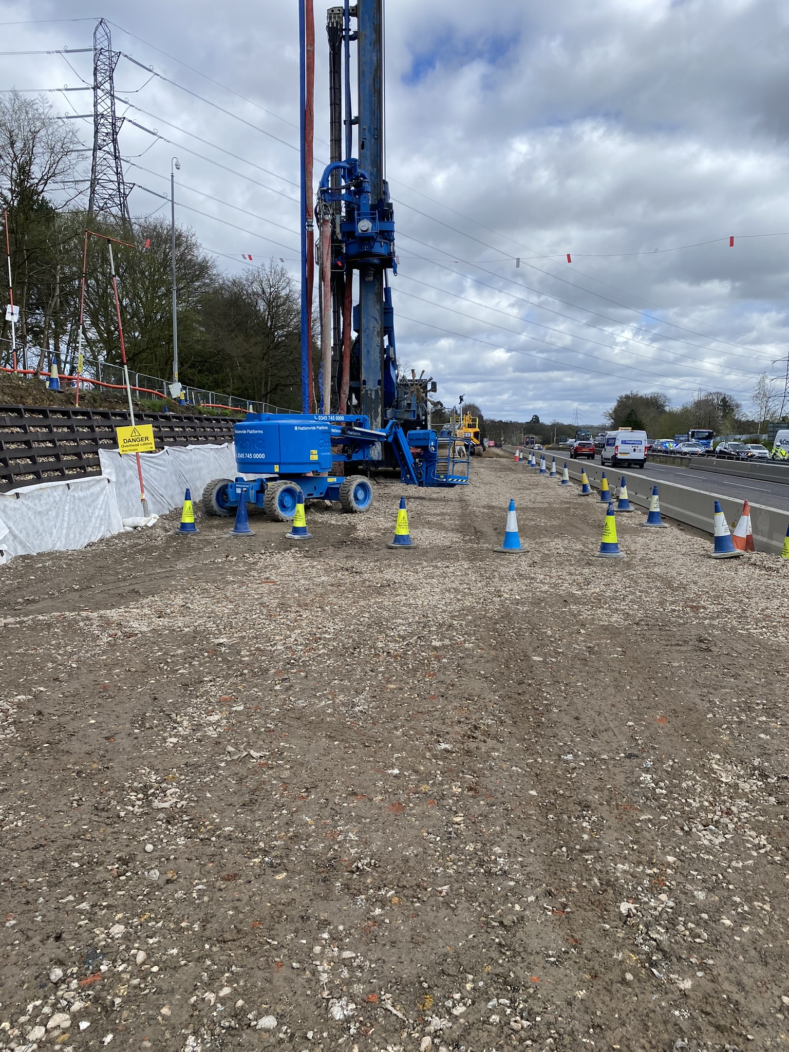
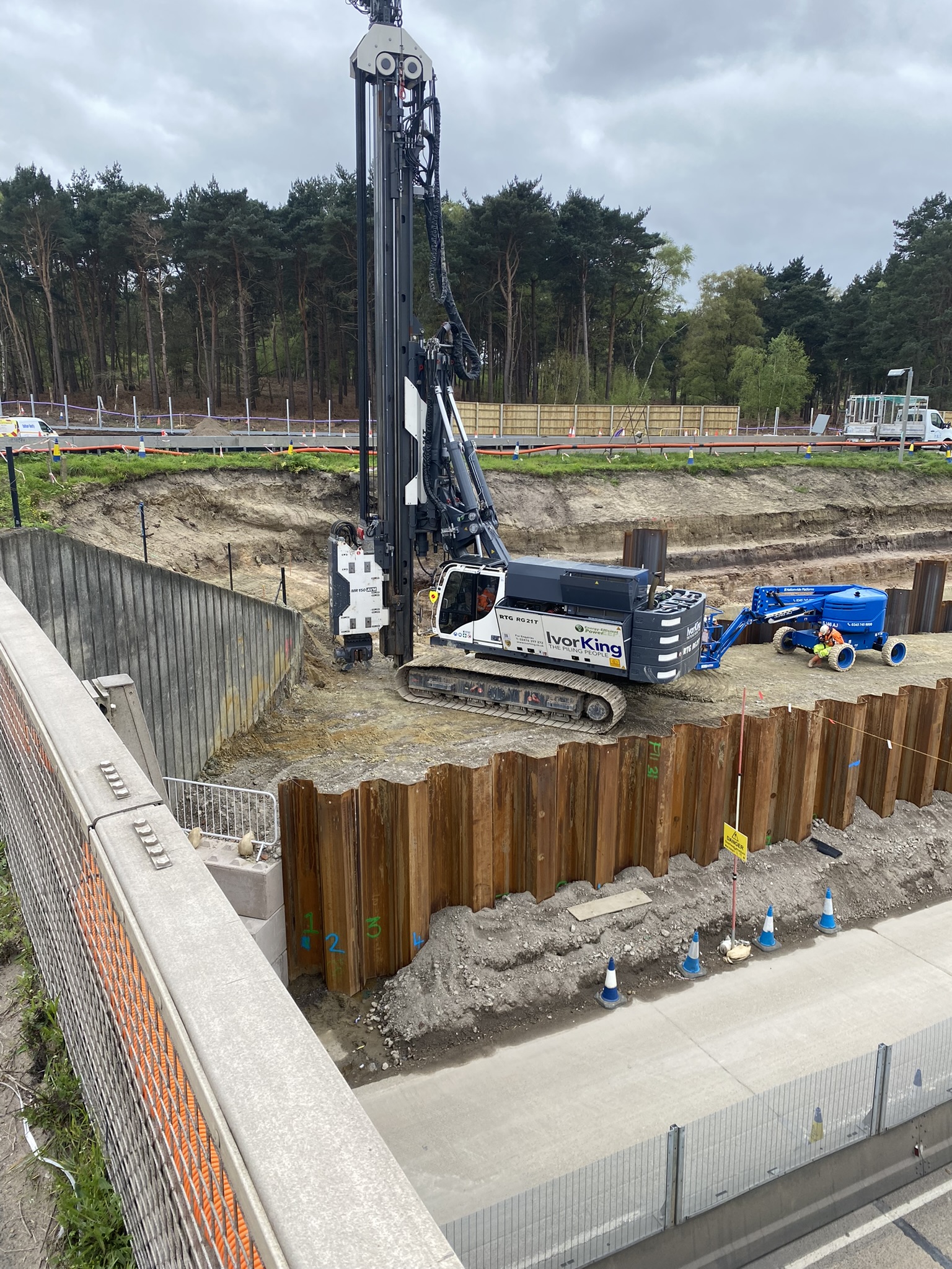
Note: all the photos are from different areas of site but demonstrate the amount and variety of temporary working platforms that are being installed. The sheet piling operations are all temporary works and are being conducted just to install some piled foundations for a bridge abutment. All of that work will be taken out once they have been installed.
A number of challenges have already become apparent on site. As often seems to be the case, there is a disconnect between the designers (who are not geographically co-located with the site team) and the reality on the ground. Some temporary working platforms have co-ordinates that place them in the middle of live traffic which is clearly not a workable solution. Others have half of the platform at the road level and the other half 5 or 6m higher with no scope to batter or step the slope due to site boundaries. When this occurs, a significant amount of time is then spent trying to establish what the designer is trying to achieve and how the platform is going to be used. This involves engagement with designers and sub-contractors so that we can construct something fit for purpose and in the right location.
I’m looking forward to getting more involved in the project; there is a lot going on and I hope to get involved with as much as I can. If you have any questions or would like to know more, please don’t hesitate to get in touch.
Temporary works design: An elongated, subcontracted solution
I’m currently working within a joint venture, in which either organisation usually take a risk-based approach to temporary works design (i.e. degree of risk dictates sign-off from a particular qualification with a certain number of years experience in temporary works design). The project I am on is similar but an early agreement with the client, within the project scope requirements, has adopted a notion supporting that all works with a risk categorisation of 1H or above (anything scoring in the high region below) requires sign off from a party external to the project (Client’s nominated authority) at the preliminary design and certified design and must be designed by a party external to the joint venture.
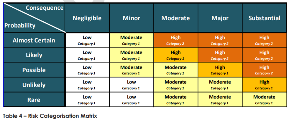
Within our temporary works design department (employed by the project), there are 5 personnel. Two of these have senior levels of expertise in temporary works design and corresponding qualifications (Chartered Professional Engineers). Within the project, all temporary works are classed as one of the ‘seven safety essentials’, which incurs a mandatory procedural approach to works, inviting more scrutiny than some less dangerous works (which I think is completely reasonable given the number of industry accidents relating to failure of temporary works making up around a third (Dobie et al. 2019)).
However, this does present a challenge to the construction team; as all works which I have come across so far (even those noted a risk category 1) have been designed and verified (as in permit to loads / platform certificates) by an external designer, which naturally incurs an additional time and financial burden. There seems to be two main designers who tender packages, both of which appear to be conservative (even within an area littered with previous GIs and their own previous designs, but that’s another story). The most evident case of this being a crane pad requirement for a double Franna crane lift (mobile cranes with notably small bearing area) of some Freyssinet gantry crane equipment (heaviest lift of 23t leading to relatively high bearing pressure (213kPa) but small zone of influence below surface due to small B). There is an existing 150mm asphalt surface (with c. 500mm crushed rock subgrade and then very compressive silt below). A previous designer (who left the project due to C-19 but was renowned for costing more but being worth every penny due to his efficiency in design) stated no need for a crane pad when the elements were craned in to place (successfully) but the current designer is stating 350mm minimum crane pad (as per their hand calculations using BR 470 – which by my understanding dictates a minimum thickness of 300mm for heavy plant anyway) with the mechanism of failure pertaining to punching shear in the weaker silt stratum below the fill.
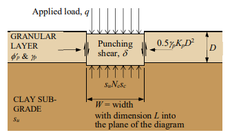
We have since (due to the lift requirements changing), changed the lift study for a 250t crane (greater zone of influence but less kPa). This has resulted in a 117 kPa ground bearing pressure (factored load with 16m radius limit applied) and have now had to increase the pad to 400mm minimum (which counterintuitively appears more reasonable due to greater zone of influence and creating distance to poor silt stratum).
There are noted policy and contract-driven reasons for the need on our project to subcontract out Temporary Works. I’d be keen to hear 1) If work is being subcontracted out, do people feel they are getting bang for their buck in terms of the risks taken by the subcontracted designer and 2) Is anyone designing and getting designs signed off in-house for their Temporary Works? If so, what sort of time and cost impact this had (number of people and hours to design and deliver). We currently experience around 8-10 weeks for certified design from submission of a Temporary Works Design Brief and varying costs (but most recently quoted c. $30k for design of 20no piling pads).
References:
- Davies, M. (2017) Design of granular working platforms for construction plant – A guide to good practice. Temporary Works Forum. Accessed on 01/05/22. Available at: <https://myice.ice.org.uk/ICEDevelopmentWebPortal/media/Documents/Regions/UK%20Regions/IGS_YGG-Working-Platforms-1705.pdf>
- Dobie, M., Lees, A. Buckley, J. & Bhavsar, R. (2019) Working platforms for tracked plant – BR 470 guideline and a revised approach to stabilisation design with multiaxial hexagonal geogrids. International Society for Soil Mechanics and Geotechnical Engineering. Accessed on 02/05/22. Available at: <https://www.issmge.org/uploads/publications/89/71/13ANZ_110.pdf>
Sustainability – Always an excuse
In preparation for my professional review I have been reflecting on how sustainability shapes the designs my colleagues and I have delivered over the last 6 months whilst working for a temporary works design consultancy (WHP).
There are a few ‘sustainability’ quick wins we have under our belt which anyone who has worked with temporary works would be able to reel out:
- We use proprietary equipment such a PERI pans and RMD Super Slims to reduce material usage because it can be reused.
- Rather than paying too much attention to the solution the Client’s TWC/TWS thinks they need, we focus on reviewing the Client’s problem to ensure the design we provide is the most economical solution. We often find that whatever the TWC has designed is over-kill and a more economical design can be provided.
- We are often able to use/re-use material that is already available on site (e.g. old ply wood used for hoarding, concrete legato blocks, scaffolding tubes etc).
However, if I’m to reflect truthfully (and cynically) I would say that the drivers for points 1 and 3 is often a matter of convenience for the Client with a sustainable side-effect. I also observed that the key driver for point 2 was more about offering value for money for the Client as a primary objective with a sustainable solution being a convenient side effect.
So why didn’t I sense that sustainability was a priority of temporary works design? I think it’s for the same reason that it isn’t whilst on military operations – the way we (or the Client) prioritises the Time/Cost/Quality triumvirate. The nature of temporary works means that it’s rarely considered sufficiently in advance for time not to be a constraint, and because cost is always a constraint then it’s quality (and consequently the solution’s sustainability) that suffers. If I reflect back to my time on HS2, the permanent works had a huge design team that had been developing our design for years and were under significant pressure to achieve sustainable goals. On the other hand our temporary works were often required yesterday in order that works weren’t delayed on site.
I’d be interested to know if any one else has identified the difference in emphasis on sustainability between permanent and temporary works?
Assessing Plant Loading on Concrete Slabs
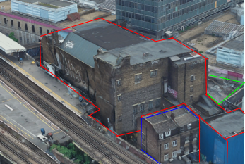
For the last couple of weeks I’ve been working for a Client (Keltbray) who was awarded the work to re-purpose a 7-storey office building at St. Pauls, London. As part of the structure re-purpose, Keltbray are required to conduct a full soft-strip and a partial demolition of certain structural slabs, beams and walls.
One of the design briefs issued to me was to confirm that the structural slabs on each floor had the capacity to support various plant including a Bobcat T450 compact track loader (see below). The T450 has an operating weight of 2,961kg, a track length of 1.28m and a track width of 0.3m.

In this post i’m going to summarise some of the quirks associated with plant loading and their load cases, and summarise some of the different methods I used to assess an in-situ slab.
Check 1 – Structure Design Loads
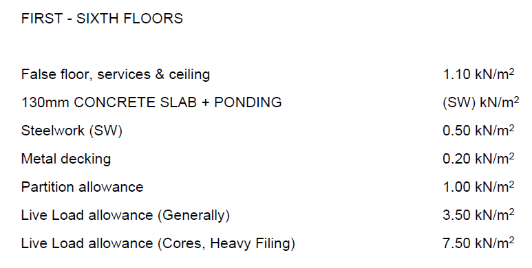
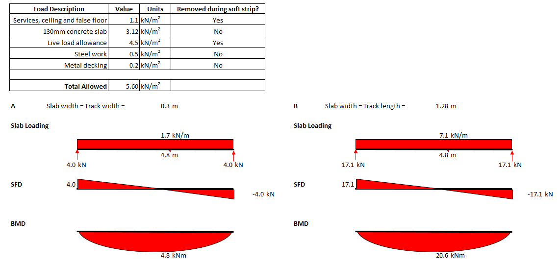
Fortunately the Client was able to provide me with a demolition specification document which defined the working loads for which the structure was designed originally. If these are available, of course the simplest check to do is to see if the pressure exerted by the plant is less than the allowable loads as specified in the design load. In this instance I knew that after the soft-strip all false floors, services, ceilings, partitions and any other variable and quasi-permanent loads would have been removed. This consequently left me with 5.6kN/m2 slab capacity, unfortunately a very crude calculation showed that the load exerted by the plant would result in a pressure of nearly 40kN/m2.
Note – When using this method there is no requirement to factor the plant loads.
Check 2 – Check Max Bending and Shear
If check 1 fails, as it did for me, the next consideration should be that whilst the plant exerts a much greater pressure than the design loads, it is only exerted over a small area, compared to the design loading which could be exerted over the whole slab span. To do this I needed to consider the various loading combinations of the plant.
Step 1 – Establish loading configurations of plant
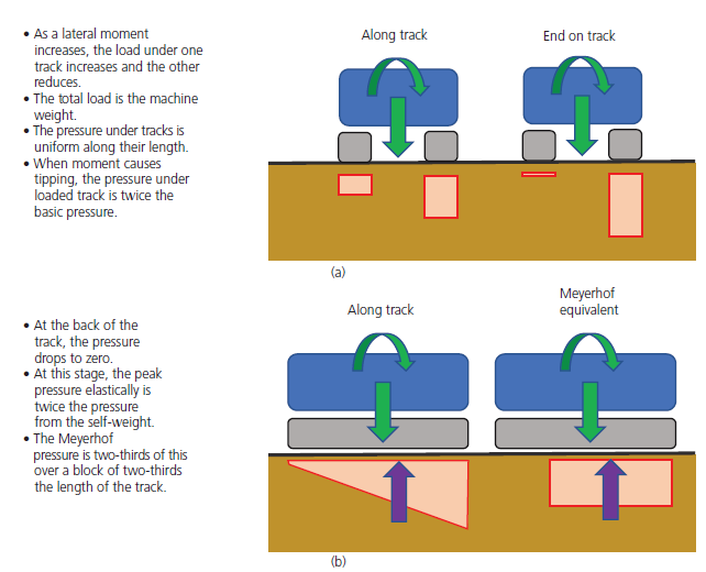
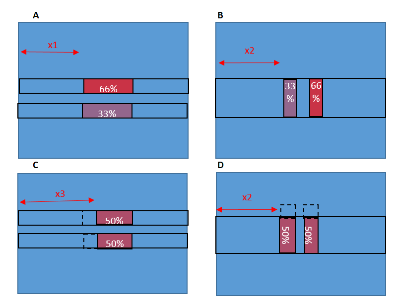
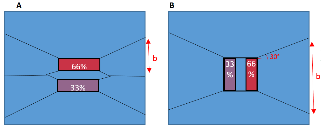
Tim Lohmann, Director at WHP, wrote an article in the ICE Forensic Engineering Journal explaining that the moments experienced by plant (through their typical construction activity) can cause an imbalance of loading. When these moments are perpendicular to the direction of the tracks, it can lead to up to 66% of the load being transferred through a single track. When the moments are in the same axis as the track direction, they can lead to a 33% reduction of effective track bearing area to due to the Meyerhof principles.
These principles are demonstrated in the figure below, for more information the article can be read by clicking ‘download’ below.
Because the slab I was assessing was one-way spanning, I had to consider both cases (a) and (b) above for the plant sat parallel and perpendicular to the slab direction. The four cases considered are in the diagram below. To find the max bending moment, the plant has been modelled at the mid span of the slab.
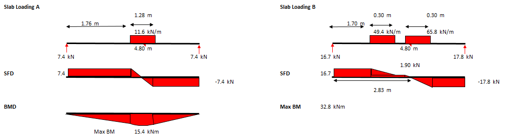
Step 2 – Calculate max SF and BM due to plant loading
The maximum bending moment and shear should then be calculated for each of the 4 combinations shown above. The SFD and BMD for cases (A) and (B) above are below.
Note – Ensure that the span you select is the maximum slab span anywhere on the floor you are assessing, as this is where the maximum BM will develop.
Note – The loading due to the plant should still not be factored.
Step 3 – Calculate Max SF and BM due to slab design loading
Using the design loads for the slab (5.6kN/m2 as determined from demo spec), the maximum SF and BM that the slab has been designed to withstand can be calculated. Below are the max SF and BM for cases (A) and (B) above. The 5.6kN/m2 pressure has been multiplied by the width of the one-way spanning slab being assessed which is a track width for case (A) and a track length for case (B).
When compared to the max BM due to the plant in step 2, you can see that the SF or BM due to the design loads is significantly less than the SF and BM developed by the plant loading. If, when checked, it is found that these BM and SF are greater than those developed due to the plant, the assessor could safely say that the slab does have capacity for the plant.
Check 3 – Slab Section Analysis
If check 2 failed then the checker should check the section properties of the slab for capacity against the max SF and BM developed in the slab due to the combination of plant loading, slab self-weight and any other loads that may not be removed during the soft strip. Whilst the plant is positioned at the mid-span, the max BM will be at the mid-span.
Note – For this check the loads should be factored.
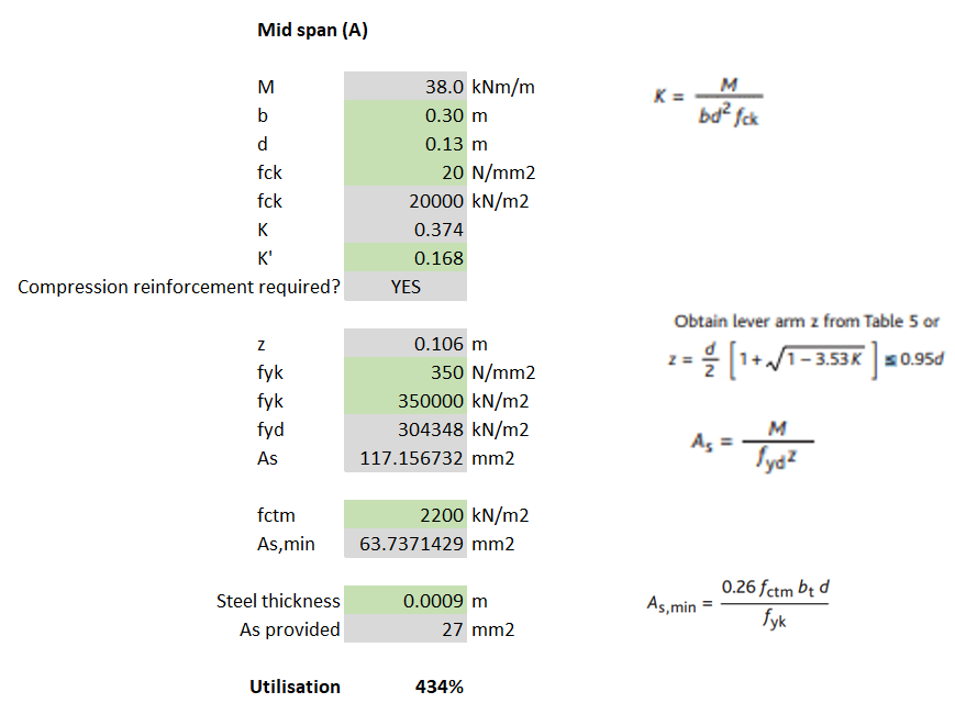
For my example, I calculated that for loading case (A) the max BM was 38kNm and then used EC2 to determine the steel reinforcement required. Because the slabs I was analysing were 130mm deep composite (steel deck) slabs, the 0.9mm thickness of the steel deck can be assumed to work as the tensile reinforcement.
Note – The yield stress of steel deck is unlikely to be the same as that for structural rebar (500N/mm2). I found it ranged between 280-350N/mm2 but check the manufacturer’s technical literature. The assessor should also check that the steel deck allows for sufficient bonding with the concrete for it to act compositely (normally achieved with dimples in the steel and shear studs).
A fundamental part of the check requires the slab (section) width to be considered. I noticed that when I considered load cases (A) and (C), where the slab width = track width = 0.3m, the section did not have sufficient bending resistance (failed by 334%) – see calculations below.
Check 4 – Assume load dissipates at 30 degrees
The assumption I had made from the very beginning was that, because the slab was one-way spanning, it was only the width of slab that was being loaded that could provide any resistance to bending/shear. However, according to BS8110-1, similarly to the way a concrete beam without shear links will normally fail on a plane inclined at an angle of about 30° to the horizontal, it can also be assumed that even a one-way spanning slab will utilise the strength of the surrounding slab, at an angle of 30 degrees.
Using the principle described above, a new b (slab width) can be determined which can be inputted into the same section analysis conducted in Check 3. For load case (A), I calculated that at the slab support, the slab width was now 1.72m. This new slab width allowed me to calculate that the slab did have sufficient tensile steel.

Note – The issue with utilising this 30 degree spread is that the same checks should be conducted with the plant moved from mid-span to close to the supports. As the plant is placed closer to the support, the max BM will reduce but so will the effective width of the slab (due to the 30 degree spread).
Additional checks required
- Whilst max bending occurs whilst the plant is at the mid-span, max SF occurs when the plant is closest to the slab support, this should be modelled to check shear capacity and punching shear.
- If check 4 (the 30 degree spread) is conducted, checks should be conducted for all 4 load combinations with both the plant at mid-span and close to the supports.
- If the slab is continuous, checks for tensile reinforcement in the top of the slab to deal with hogging should also be conducted.
Summary
When working for a design consultancy, the efficiency with which we carry out these kind of checks is what makes the company the most money. This post demonstrates a hierarchy of checks that can be used, from most basic to more complex until I reached the stage where my check passed. Whilst the labour intensive check 4 gives the highest chance of a check passing, a quick check might show that the simpler checks 1 or 2 might also pass (and take a fraction of the time to complete).
If even check 4 fails then FE analysis may be required. Otherwise it might be time to tell the contractor that they either need to downsize their plant, or back-prop their slabs.
RMD Megashors: Failing by over 30%
Project: Fulham Riverside.
Context: RC framed multi storey building. Constructed. Columns needed to be replaced. This required temporary propping. Propping designed by external company consisting of RMD Megashors. The consultancy I’m working for were asked to check the scheme.
Event: We identified that the Megashors were inadequate for the loads. Failing by over 30%. The external temporary works designers had calculated the prop loading correctly, however they used an incorrect prop capacity. The capacities used were taken from an out of date datasheet.
A few years ago, the published capacities of RMD Megashors were significantly reduced. This occurred because one of the manufacturers had used an inferior grade of steel for a period of time. You can see from the diagrams below, taken from the technical literature from 2009 and 2017, that for a 3.5m effective length, the capacity has been downgraded by nearly 250kN!
Interestingly, the external temporary works designer knew about this however he was led to believe by his supplier that the RMD props that were being provided to him were of the higher grade. However, when asked, the supplier was not able to confirm this with documentation.
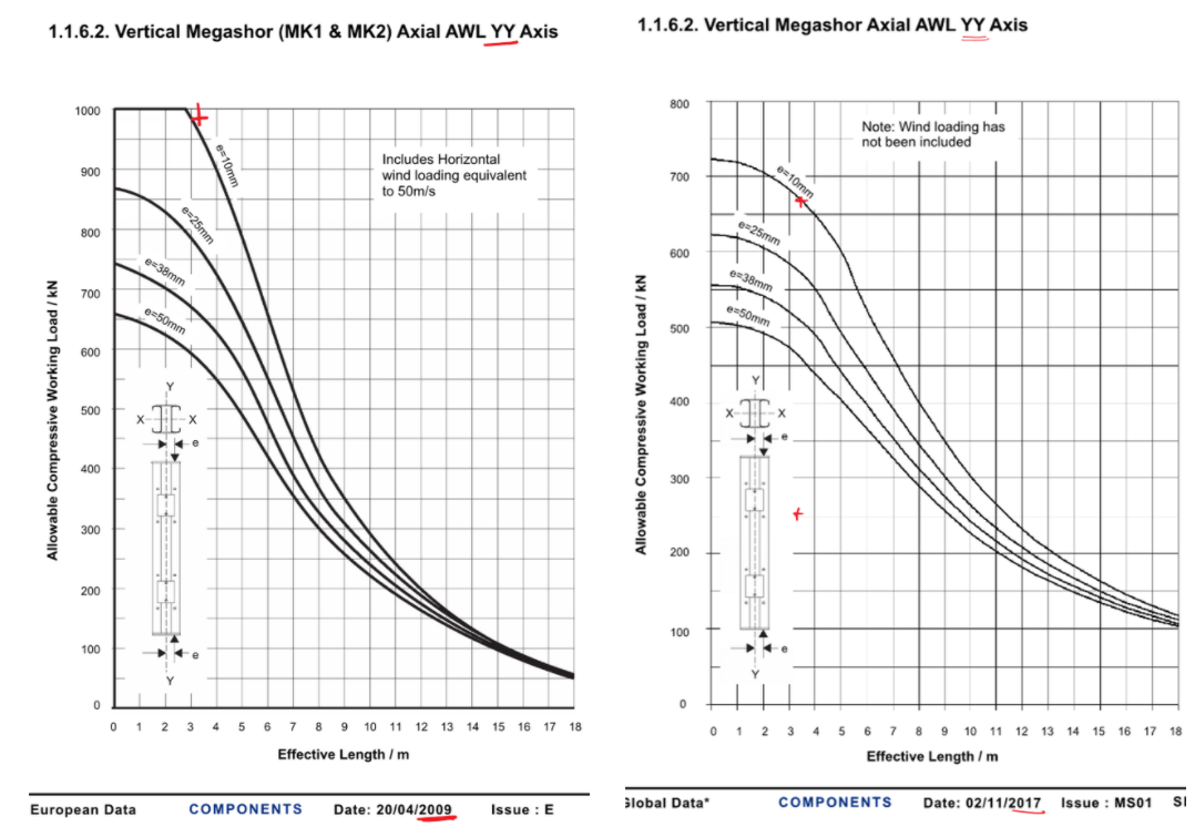
To compound the issue, when RMD originally published this, they announced that they had no method of identification (e.g. batch number or serial number) on the props, so determining the age of a prop and therefore which grade of steel is near impossible. This is why they took the huge commercial decision to downrate all of their Megashors. I guess it could be easier for a supplier as they would know when they bought their props, rather than RMD who I’d assume have a floating stock that is regularly replenished.
It is also interesting to note that the old spec allows for 50m/s wind as a horizontal load, but the new one doesn’t allow for any.
Lessons Learnt: When using RMD megashors, ensure that you are using the latest technical datasheet. If a supplier says that their grade is of superior grade, then the onus is on them to prove this.
The 2017 Megashore datasheet can be found here so you don’t get caught out although this demonstrates that it’s always worth checking to see if there’s a newer version!
Preloading your backprops for maximum load distribution
Read time: 10 mins.
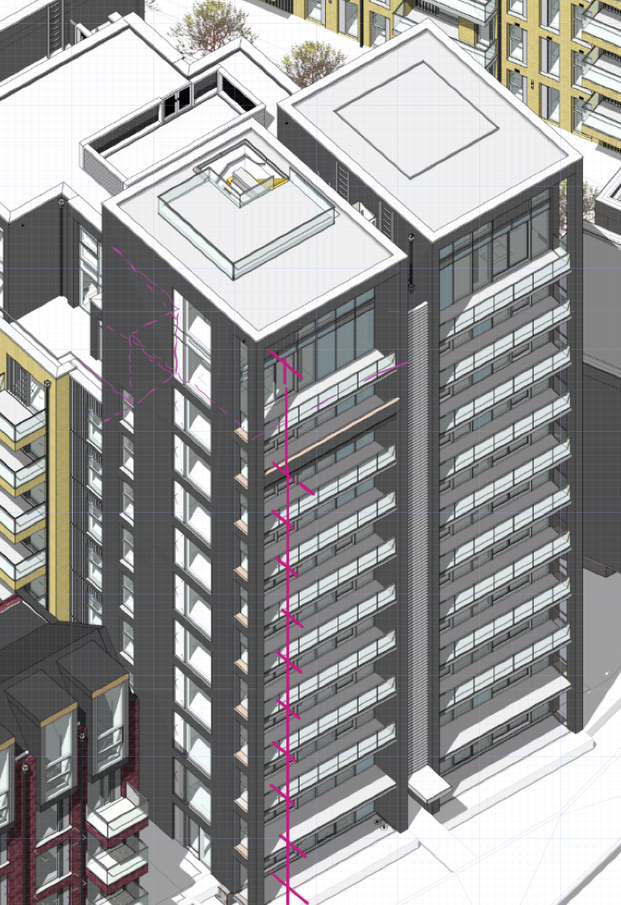
One of my first tasks on Phase 3 has been to develop a temporary works solution to support the demolition of the roof (RF1) and 3 levels (L01, L02 and L03) of suspended concrete slabs of the Coronet Theatre in Elephant and Castle. In order to demolish these elements, an 8 tonne excavator will be lifted onto L03 and break RF1; once completed the props on L02 will be removed and the plant will be lifted to L02 so that L03 can be demolished and so on.

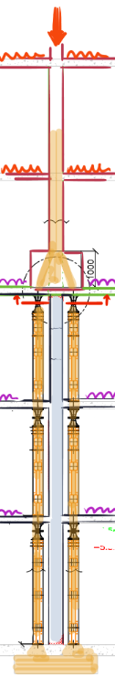
Specifically, I have designed a back propping system to transfer demolition loads (plant and demolition debris) from suspended concrete slabs to the ground. Back propping is required because a cursory check tells us that the concrete slabs were designed for imposed loads much lower than those imposed by an 8 tonne excavator and up to 0.5m of demolition debris.
As you can see from the diagram, the loads from the working platform will be transferred directly to the ground, however, in the development of this solution I considered transferring the loads to L02 and L01 only to save the Client the use of the costly Titan props used on the ground floor. In doing this I used the principles taught to us in applied structures (by JAM I think?) that were summarised by Pallett (2016) typically used when designing falsework, see diagram below.
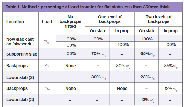
Pallett tells us that with two levels of back propping, I could distribute 65% of the demolition works loads onto L03, 23% to L02 and 12% to L01. With just one level of back-propping this distribution would be 70% to L03 and 30% to L02.
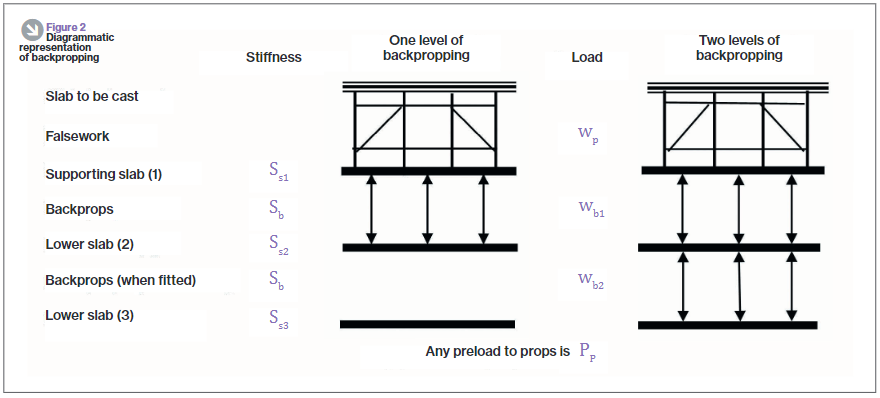
One might expect that with the use of a rigid prop, deflection in the top slab would equal deflection in the supporting slab as shown in the diagram below. If this was true then the load on the top slab would be split equally between the top and supported slab, 50% of the load to each. In essence, the two slabs become one member with the slabs acting as flanges and the props acting as webs. So why does Pallett tell us that the loads would be distributed 70/30, not 50/50?

The answer is because the props too act elastically and shorten when exerted to the axial load as required by d=PL/AE. If the member can’t shorten, then the load can’t be transferred. Instead, the interaction between the slabs and props looks much more like that in the diagram below. There it can be seen that the deflection for the top slab is greater than that of the supporting slab.

Preload your backprops!
Unfortunately it was still assessed that even 65% of the load imposed by the demolition works would be too great for the suspended slabs and so I looked for other solutions, determined not to use the expensive lower level Titan props. I had seen that Pallett released a further article in TheStructuralEngineer in 2017 that suggested that backprops could be pre-loaded, an interesting concept that I thought I’d look into.
Think about how you install a prop, typically you stand it between the supporting and supported slab and begin to twist the collar, extending the prop until it is firmly wedged in place. Well what would happen if you kept twisting the collar, perhaps using a sledge hammer or using a long spanner as a lever? The answer is that the top slab would start to hog and the bottom slab would begin to sag. It turns out that by doing this we can actually achieve the conditions so that the load can be shared equally between slabs, 50% each for a 2 slab system or 33% each to a 3 slab system as is the case with my problem in Elephant and Castle.
How to design back-propping
It’s all very well knowing that by exerting a load on the supporting and supported slab by preloading your backprops you can distribute loads imposed on the supported slab equally, but how can this be designed? It can be designed by the basic application of PL/AE.
Take the following example:
E: Prop material stiffness = 69 GPa. The Youngs modulus value for aluminum.
A: Prop section area of material = 0.00259m2. Taken from manufacturer’s technical literature.
L: Length of prop = 2.982m (distance between slabs).
P/d: The force per mm extension, kN/mm.
and rearrange the equation so that P/d = AE/L. We can then work out that for every 1mm the prop is extended, it exerts a force of 60kN. If we also know from the technical literature that one thread (turn) equates to an increase in prop length of 2mm, the instruction to site in order to exert 30kN to the supporting and supported slab each (60kN total), would be to give the collar half a turn. Tests carried out as part of the European Concrete Building Project (ECBP) found that by using this method with a prop system, you could practically apply an upwards UDL of 0.5kN/m2 on the bottom of a slab.
Of course, if using this method to equally distribute loads there are a few things that need checking:
- Has the supported slab got sufficient reinforcement to tolerate the hogging due to the applied upwards force; a typical concrete slab would have maximum sagging and minimal hogging reinforcement at mid-span.
- Are the loads acting on the supporting slab (self weight, load imposed by preloading props, shared load from supported slab, other imposed loads) within the capacity of the slab.
- As the axial force in your props increases so does the likelihood that they will buckle, they might need restraining with ledger frames.
The ECBP found that this method was difficult to implement with thin slabs because of their flexible nature leading to the tendency to transfer load between adjacent props as one is tightened up.
In all there’s nothing ground breaking here but a bit of applied engineering to distribute that little bit more load between your slabs, it might just make the difference.
References:
- Temporary Works Toolkit. Part 4: An introduction to backpropping flat slabs. Pallett, TheStructuralEngineer (2016)
- Temporary Works Toolkit. Part 6: Backpropping flat slabs. Pallett, TheStructuralEngineer (2017)
