Big buildings, banks and basements
Project Armada
I have been assigned to The London Development which is the design and construction of a nine storey, one million square foot Goldman Sachs headquarters building. The project is at stage C-D and I have been tasked with the basement, retaining walls and raft foundation aspects.
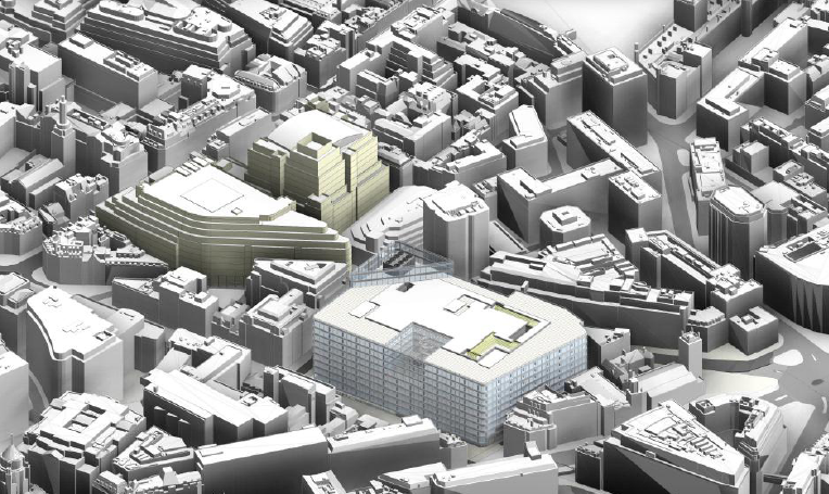
Architects image: the maximum height of the building is limited by the Greenwich Park to St. Paul’s viewing corridor, creating a demand to maximise the floor area .
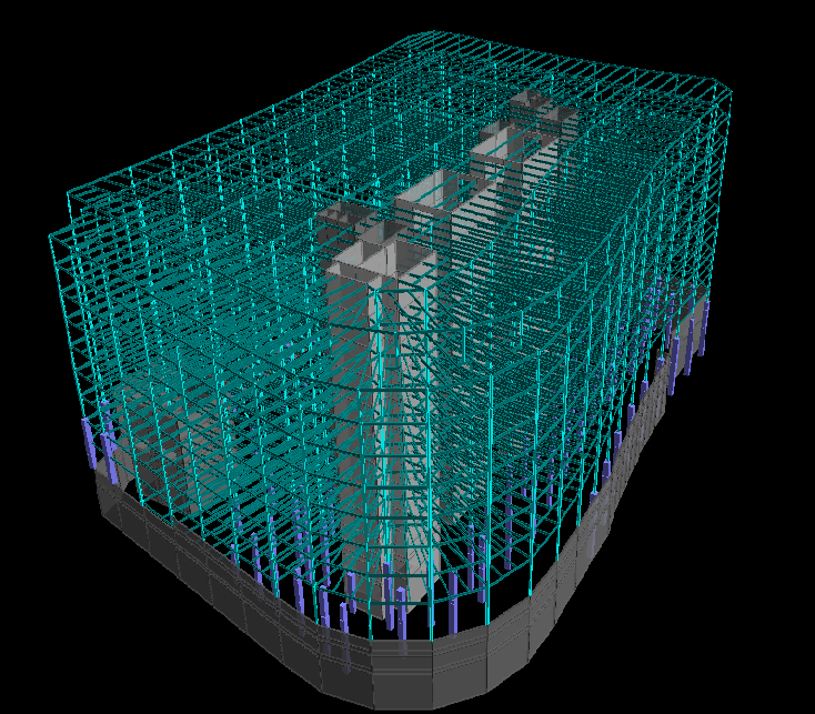
The initial superstructure model with 9th iteration of core walls layout and 4th iteration of column grid layout!
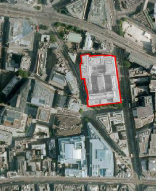
Site on Fleet Street in the City of London currently occupied by 2 buildings.
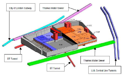
In addition to the above ground site constraints, The London Development is underlain (aside from the old Fleet River) by several below ground tunnels, chambers and utilities. Of which three substations and a access lift shaft have to be maintained within the basement, making the construction sequencing a critical component to the design.
Design Lessons Learnt
Having completed 6 days of Structures Graduate Proficiency training over the last couple of months, it is clearly apparent that aside from the core syllabus of revising first principles and Eurocodes, the priority is to teach graduates how to design to save money and make money! i.e. how to incorporate economy into design and how to get the right answers (to an appropriate level) in as little time as possible! Given the size of buildings WSP Structures department generally deal with, this skill is key to maintaing a profit margin – time is most definitely money all the way to the 70th floor! Perfecting the art (certainly during the initial design phases) as far as I have ascertained, seems to be rules of thumb first followed by optimisation through software. The first comes naturally to those with experience, or eventually with a bit of guidance for graduates or newbees! A few new designers lessons learnt so far:
1. Apply rules of thumb (i.e. quick designers assessments of member sizes and configurations) to the problem first, just to get an idea of what the loads and forces are likely to be so that you know if your answers are at least in the right ball park. These are contained within most guides but do not require trawling through the Eurocodes and should only take less than an hour to produce.
2. Understand the geometry of the problem fully before embarking on any design. I have found drawing lots of sketches and asking colleagues if that is what is required saves a lot of time in the long run. This will firstly ensure your part of the design fits within the overall structure (and you are using the same parameters) but also basic components like the slab is spanning in the right direction for example!
3. Consider construction aspects in the design Intrinsically tied to the cost of materials is the cost of construction. Whilst the consultant does not price the construction, the client will soon establish how economical the design is when the contractors submit their tenders. In my case, I had to give the Client a ribbed slab vs composite slab solution for a bespoke 100 person conference room. Whilst the ribbed slab came out considerably deeper, the additional cost of bringing steel into the construction sequence to maximise clear floor to ceiling height will have to be weighed up by the Client. Another aspect which I hadn’t initially considered was additional opportunities for temporary works savings, for example ensuring the beam is the same height as the ribbed slab, thus increasing the width with a set depth of the beam to reach the required capacity. Where the designer employs these techniques however, it is often then necessary to explain the reasoning to the QS who may only be looking at the cost of materials!
4. Initial design = initial design After spending hours producing reams of detailed designs, the client would then want a column grid change or an adjustment to the proposed floor plan! Whilst this should theoretically stop after the agreed “design freeze” date, either the date continues to slip or it will happen anyway and a concurrent commercial debate about whether it is design development or a change in specification will ensue! The answer at engineer level is to minimise detailed calculations at this stage and maximise use of spreadsheets or software where parameters can be easily changed. This also ensures that unnecessary time is not logged to the project which will be required during the detailed design stage.
Site Visit
I visited the One Blackfriars site, a 170m residential and commercial tower with the geotechnical and structural engineer responsible for the groundworks phase of the construction. Much like the Shard, construction will be simultaneous top down, bottom up construction, hence the requirement to install a series of plunge columns and cast the ground slab prior to further excavation.

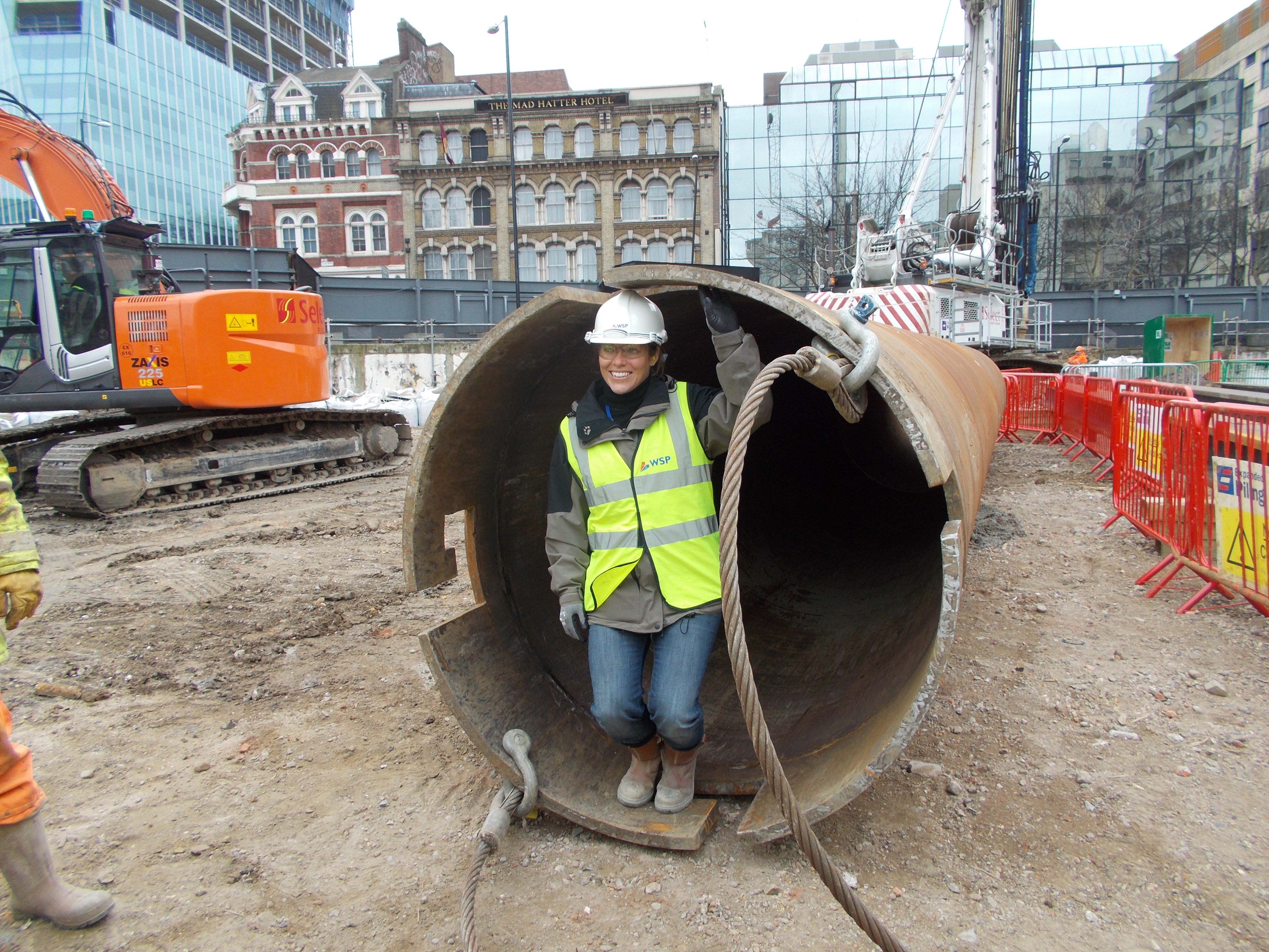
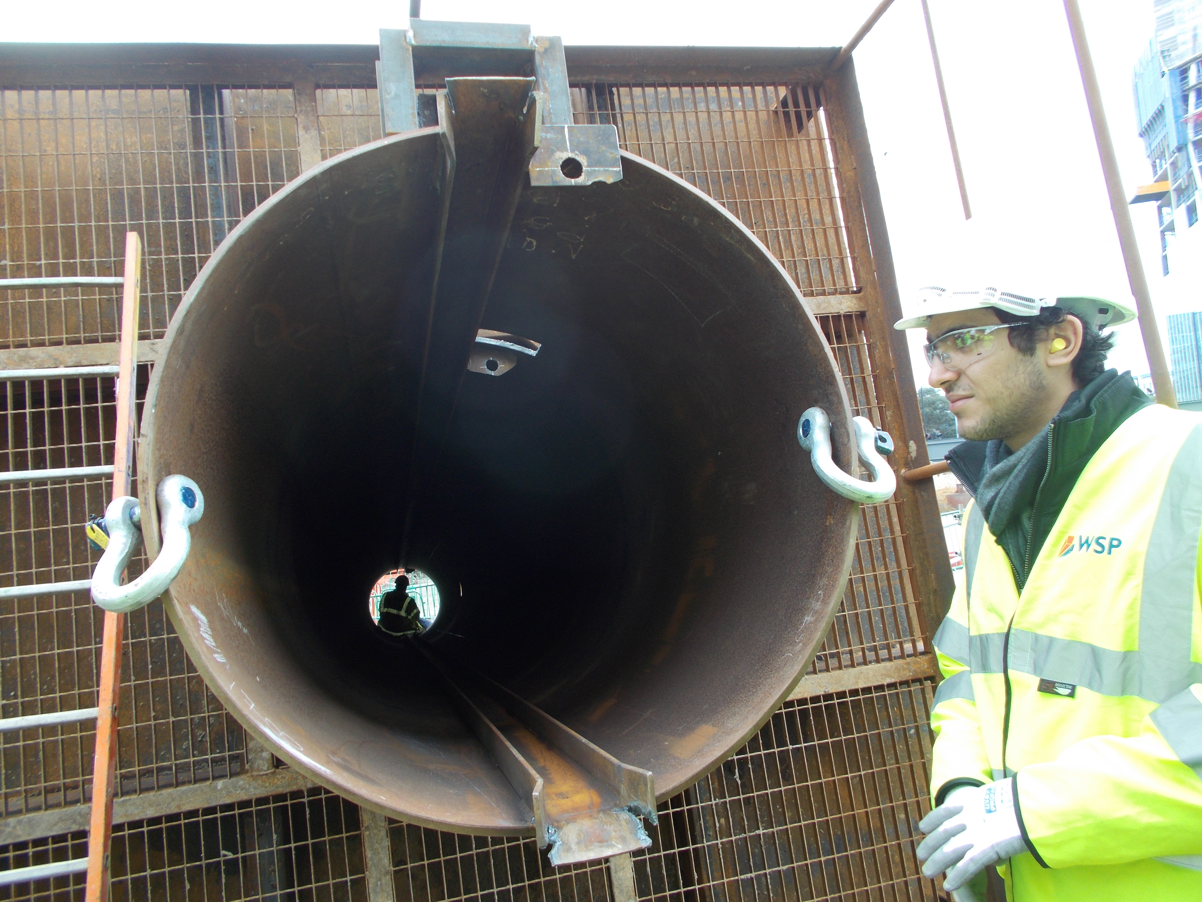
A plunge column casing (of which I was asked to demonstrate how tall is was…almost 6ft…?!)
The contractors were in the process of installing the plunge columns using a best practice technique developed by piling contractors. A bespoke casing was fabricated with guide rails which allowed the column (also fitted with guide posts which can be fabricated to the required length) to be fed into the casing, levelled and hung from a steel beam until the concrete has reached the minimum strength requirement. The size of the columns is dictated by the loads as well as the levels of tolerance required.
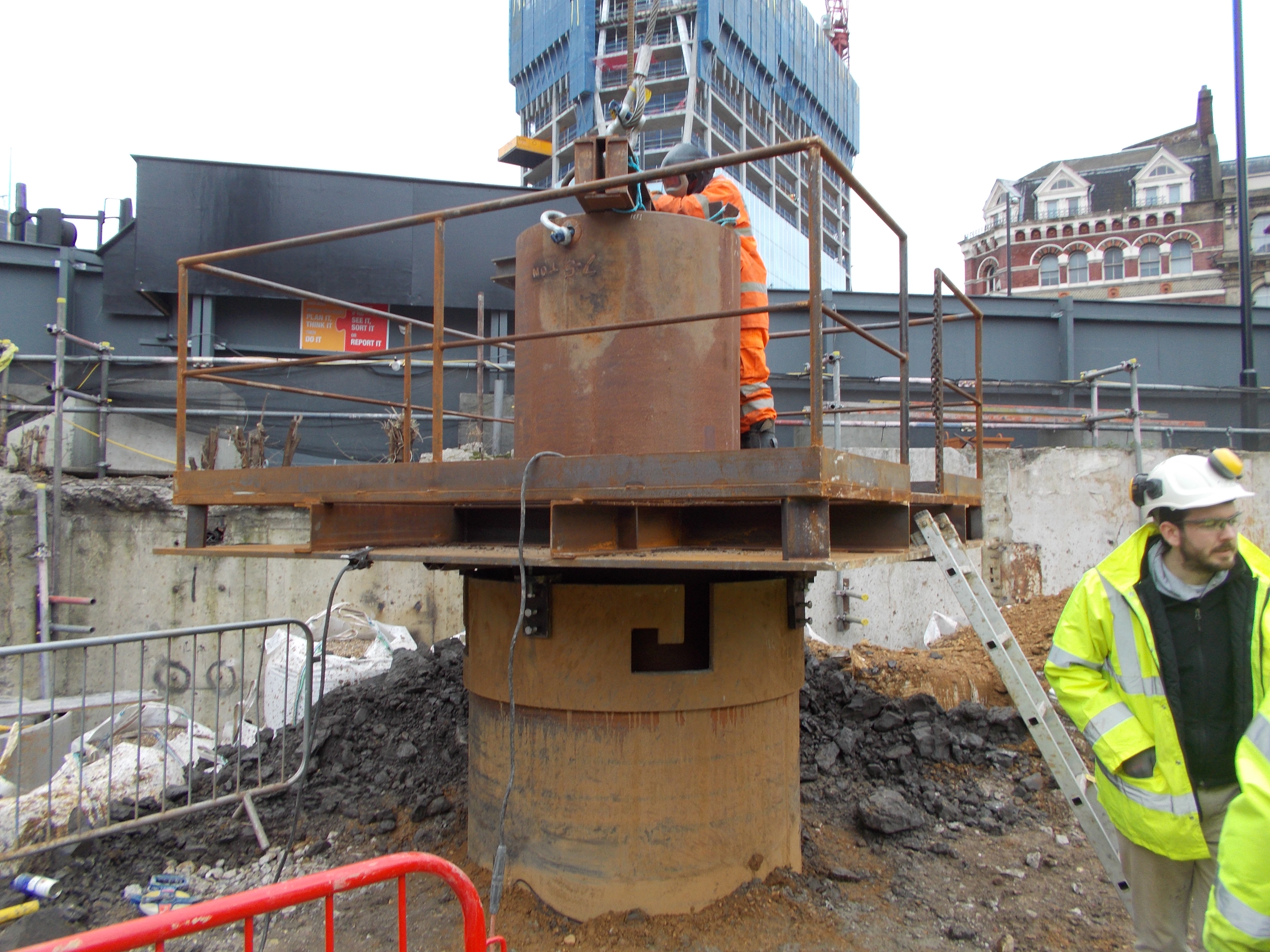
The plunge column installed in the concrete filled pile, hung from the beam shown and welded for security until concrete reaches required strength.
Another best practice technique used on the site was bags of shingle as temporary propping following excavation adjacent to the road, saving on bespoke temporary works and utilising the shingle in the final layer of the plunge column piles. Very Royal Engineers I thought!

Hi Rachel,
At last the internal Blogoshere is allowing me to post comments again! Like the design thoughts – I considered comparing it to a lecture script here but decided that similarities would be due to significant common factual information and not plagiarism. Nice to see that the rubbish we try to push out in the classroom falls into place in phase 2 & 3. I’m guessing there are several rafts at different levels and with interesting movement joint arrangements that need to run right through the superstructure so look forward to hearing more…
Well Done R.
Rachel
What with top down and bottom up…I am reviewing for the ICE next Tue and one of my candidates is using lots of plunge columns – at least I know more now. Thanks
Lots to talk about at CPR.
Rachel, I too am experiencing the design freeze challenge where, despite having 3 of them now, the design is still changing! It’s a pain as I’m working on utilities and services relocations so having bridge abutments into locations where major telecoms pits are is a real imbugerance.
Some bits for the uninitiated and some Q’s :
Stage C and D are in the Architects’ Scheme of Works which structural engineers working to an Architect often follow. It’s a good work breakdown structure for the process of providing design services C=Coceptual and D= Design Development
I’m interested in a few bits:
a) Looks like you’re running off a RAM model…..? At what stage do WSP build these?
b) With the height restrictions common in London it is usual to minimise the floor-floor height to get 9 lifts in what would otherwise be 8 and therefore increase the rentable floor area by over 10%. For this the structural height plus service zone has to be minimised. WSP were once fond of cellular steel beams (particularly from FABSEC, for some reason). What are the structural options considered here?
c) You say that it is a raft foundation. Interesting. So often in Central London the foundation actions have to be taken down around the myriad of service tunnels to avoid surcharge. Is this a buoyant raft?
Thank you all for your comments. In reponse to the raft questions, which ties in nicely with your floor height restriction question John – the initial Stage C option was a Raft, however, following some considerable grid layout changes, and hence doubling of the load on some internal columns, the initial raft design is under review, proposed options are: deeper raft foundation; piled raft, suspended basement slab onto piles. The relative effect of each option on underground services is being modelled by the Geotechnical engineers. Either way, I am looking at a revised raft/basement slab/pile and pile cap design for the Stage D report…..answers on a SAE…!
The continual grid rearrangement was as a result of optimising floor (and very expensive) Banker desk space! And yes FABSEC cellular steel beams are still particularly popular at WSP! The building is divided into a concrete (up to level 1) and steel (levels 1 – 9); options include, cellular, plate girder, composite and ribbed slab options (floor use dependent), with the emphasis on floor-floor height and maintaining the steel/concrete construction divide. The RAM model is generally generated during Stage C, but only developed in detail during Stage D.
Hope all well. Many thanks.