Dream Beam
The final installation of the transfer beam was absolutely perfectly. The use of the steel angle to set out the bolts was the right choice and the beam sits within 3mm of where it was designed to be. Below is the article I have written for the Company update, Osmosis, much like Blackadder’s ‘King and Country’ and our very own Soldier it’s pretty much propaganda but they seem to like it.
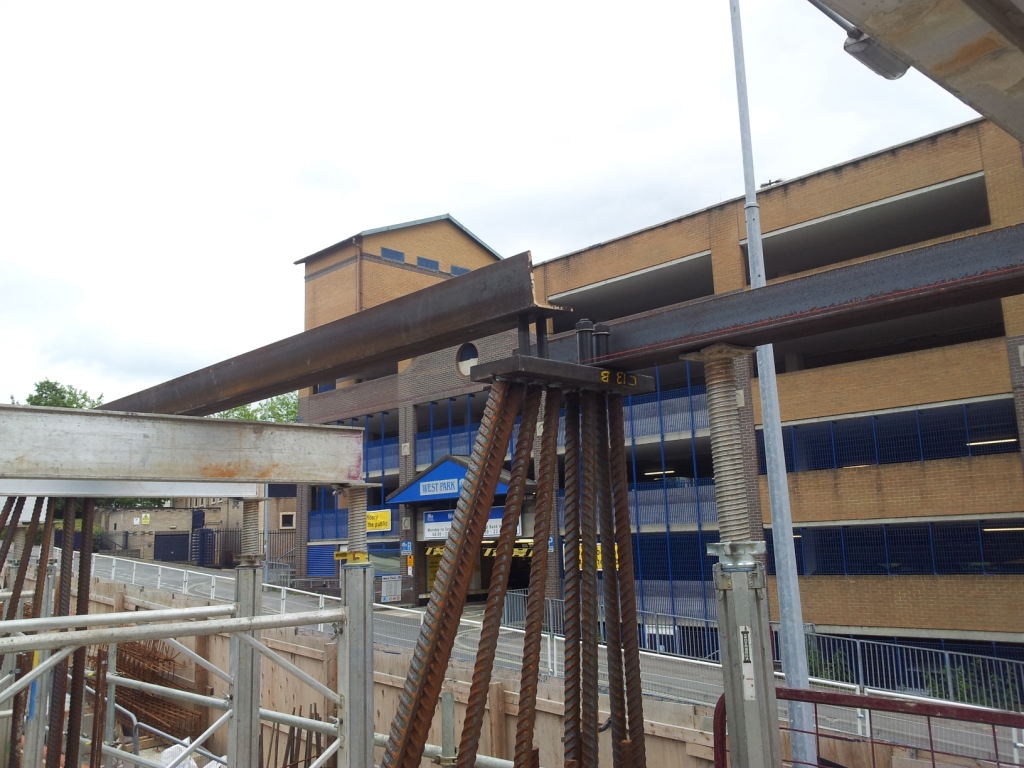
Steel plates and 40mm bars that were tied into the columns, note steel angle fixing the 30mm diameter bolts in place.

100 tonne mobile crane lifting one of the beam sections into place.
Dream Beam
An out of hours road closure and crane lift on Monday, 1st July saw a critical element of the Mayflower Halls project completed smoothly and in half the time allowed.
A large transfer beam was required on Block B, the tallest of the blocks on the project at 17 stories, due to a change in the column lines on Level 02, with so many floors above the beam the actions involved necessitated an enormous beam. Originally a specially made plate girder was designed, however in order to reduce procurement time a standard Universal Column section was used with additional plates welded to key areas. The main beam was delivered in 3 sections that when spliced together totalled over 23 metres long and weighed in excess of 15 tonnes.
In preparation for the beam eight steel plates with four bolts welded on were tied into RC columns using a steel angle as a template, once the columns were cast the steel angle was removed ready for the installation of the main beam. Rigorous setting out and checking by Senior Site Engineer Phil Dowling ensured the holding down bolts had been positioned with the precision needed.
Careful planning and liaison with Southampton City Council secured a partial road closure on one of the City’s busiest bus routes for four hours on both Monday and Tuesday evening. A 100 tonne mobile crane was used to place the sections of beam on the columns. The beam located perfectly over the holding down bolts and was in place within a single evening avoiding the second road closure and extra crane time. Site Manager John Wild said, “It was great to see so many different people working together to ensure success.”
Something that won’t be appearing in the next newsletter is the 4.5m high 7m long, 300mm thick retaining wall that sits directly below the transfer beam that will be removed in the near future due to a design error putting it 75mm too far in the footway and forgetting to include the louvres that were required.

I sort of recall you saying that the original design of the transfer beam was rc – rather than a plate girder and that the transfer beam you ended up with was a composite beam ….all too much for the newsletter?
My oh my but you’ve gone into ‘the Sun says” mode there …let’s hope the TMR is more Times Insight Team.
With a Board that’s full of accountants it’s better to dumb down than have Josie from communications try and interpret what I’ve written. I thought that was the introduction for TMR 2 in ther bag personally.
By the way John, I spoke to the structural engineer who told me they completely ignored the concrete in compression, it only serves as dead weight and fire protection for the beam. He couldn’t understand why I was so happy, no shear flow calcs for me then! Phew.