Archive
Self Made Issues
A temporary blip on the blogging last week where I just plain forgot, so apologies all round to anyone that reads them!
A few issues have cropped up over the last 2 weeks in and amongst the frantic push to meet a $20m milestone payment by the end of June. I think my last post eluded to the colossal amount of work that was required to meet the deadline and the equally large chance of a storm pushing through to make meeting it that little bit harder. The long and the short of it is that it was an uber busy week but we eventually poured the 4th slab in 7 days – for those of you who are interested, that’s approximately 100m3 of concrete. Good efforts all round.
The fallout from the epic push is that whilst all attention was focussed on reaching the milestone, very little was actually done to plan for future tasks. The following issues have arisen as a direct result of simply not have enough time/manpower to keep up with construction.
- Stair 9 Internal wall. The initial pours of Stairs 8 and 9 had many errors and were quite out of plumb in places due to an initial rush in the early phases of the project to get them poured. We have reaped the rewards of this by slowly closing out NCR’s with structural engineer input to bring them back into tolerance over the next few levels with no significant effects. The particular issue that could easily have been avoid was a lack of starter bars immediately next to the door (see image). I had a look at the initial setup of the formwork and discussed the missing starters with the steel fixers. I left it that if required, the error was theirs and they would have to drill and epoxy new bars in. As it turns out, they were not missing, the internal door had been set out wrong by the formworkers. By the time I had investigated this the steel fixers, pressured by site managers, drilled and epoxied and fixed the steel in the form. I had to order them to rip it out and cut the bars off when I found out. Sad faces all around. The issue now is who pays for the work conducted by the steel fixers. JHG won’t stump up because the work was conducted without JHG approval, so it looks like the formworkers will pick up the tab. I am speaking with commercial this week to discuss.

‘Missing’ starter bars at the edge of the wrong door set out
- Stair 10 Landing. When stair 10 was poured the couplers/starters were not installed as they were not delivered in time. The decision was to drill and epoxy new starters around the perimeter. A site instruction was written to the steelfixers to conduct the workswhich were detailed as N16 bars to be drilled 225mm into the wall (to internal edge of external steel) at 200 centres top and bottom of the landing. This work was completed and JHG informed that all work was in line with design and standards. On inspection it was noted that the bars were not at the correct spacing (but that could be put down to drilling around wall reinforcement) and also the ends were not aligned. ON closer inspection and a slight tug, a couple of bars came off in hand! To put this in context, the building is designed as a post disaster structure that feasibly could have a large imposed loading if people are rushing to evacuate the building. The landing is solely held up by the drilled and epoxied bars. This negligent work could have potentially caused additional collapse of the building. We are currently awaiting the outcome of a further investigation to ensure the work is completed adequately. To me this highlights the lack of personal pride in ones job and a complete lack of understanding of why they are doing something. It further highlights the problems with hiring 3rd tier contractors and the lack of any checks to ensure competence when hiring.
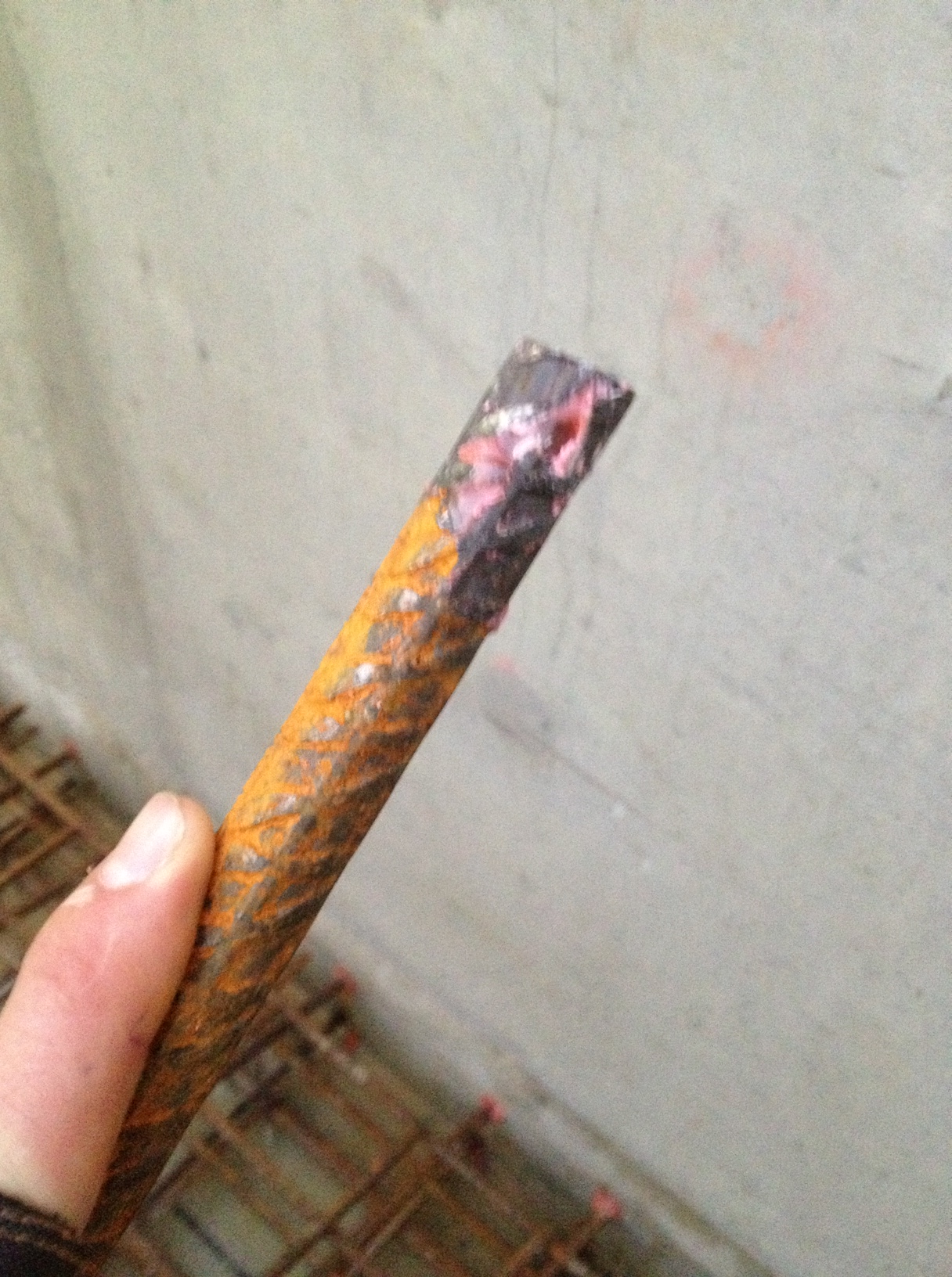
The hand removed N16 starter. Now I’m no good at estimating length (Nicky tells me) but that ain’t 225mm!
- West Block column. After the long drawn out negotiations with the client to decide the method an of pouring and finishing columns the following occurred 1 week afterwards. To top it off the Clients representative was at the stripping of the formwork with his Ipad looking for the density of blowholes in the surface finish – he got a bit of a surprise! It is assessed that the concrete was not vibrated adequately and the consistence was not sufficient. Therefore both JHG’s quality assurance and the concrete contractor for not carrying out the task correctly. The issue was escalated by the state to the WA Ops Manager who personally emailed the site engineer to express his dissatisfaction – not I would argue good management. A suggestion that it would be a good feature column in the X-Ray department was not taken well.
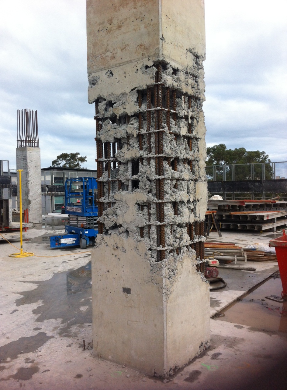
The X-Ray Column
What this highlights to me is that a project must be adequately resourced to match the construction programme in both management and workforce. To not resource a project effectively is to delay the decision making process which will have a detrimental effect on progress.
The Construction Director who was pushing the programme (I think his job may have been on the line) has finally accepted that 2 engineers for the whole of the South block is simply not enough. A new engineer started who will be solely responsible for the Core C riser and jump form, and the rumour on the jungle drums is that a further engineer who was destined for the basement may be poached temporarily to reinforce the South team until the basement kicks off. Time will tell.
In other news, we had the Dollimore’s over for their last night in Australia this weekend. We had a fun night out with a few guys from the NCH to say goodbye, and a final breakfast at the beach in Cottesloe. Then it was time to head back to AER for me so I had time to finish in time for the Lions game. We set up the projector in the house and had a few mates over for a BBQ – Great game! Actually looking forward to work tomorrow now after the abuse I got last weekend!
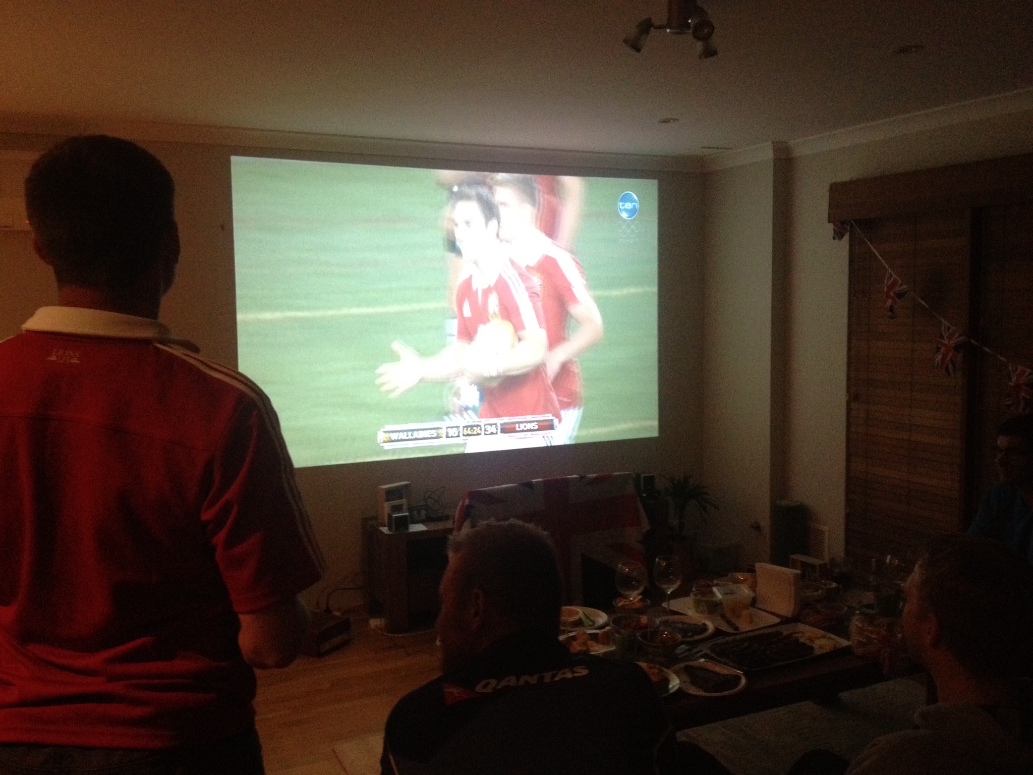
Home Cinema – al the better result when surrounded by Aussies!
Dream Beam
The final installation of the transfer beam was absolutely perfectly. The use of the steel angle to set out the bolts was the right choice and the beam sits within 3mm of where it was designed to be. Below is the article I have written for the Company update, Osmosis, much like Blackadder’s ‘King and Country’ and our very own Soldier it’s pretty much propaganda but they seem to like it.
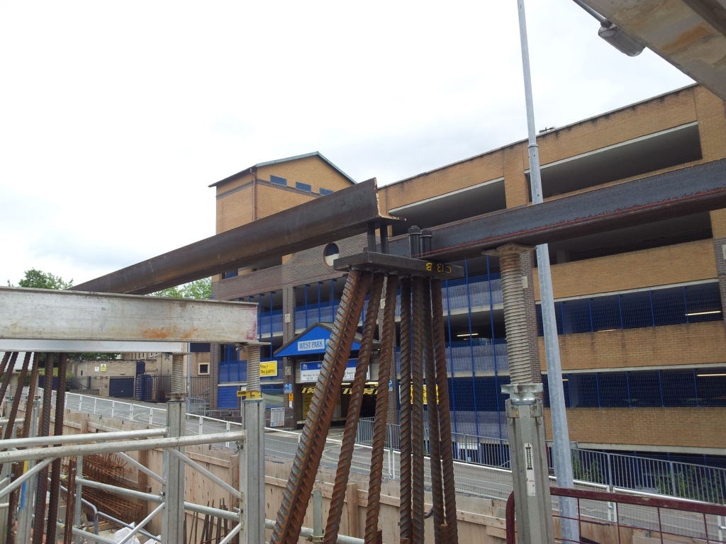
Steel plates and 40mm bars that were tied into the columns, note steel angle fixing the 30mm diameter bolts in place.

100 tonne mobile crane lifting one of the beam sections into place.
Dream Beam
An out of hours road closure and crane lift on Monday, 1st July saw a critical element of the Mayflower Halls project completed smoothly and in half the time allowed.
A large transfer beam was required on Block B, the tallest of the blocks on the project at 17 stories, due to a change in the column lines on Level 02, with so many floors above the beam the actions involved necessitated an enormous beam. Originally a specially made plate girder was designed, however in order to reduce procurement time a standard Universal Column section was used with additional plates welded to key areas. The main beam was delivered in 3 sections that when spliced together totalled over 23 metres long and weighed in excess of 15 tonnes.
In preparation for the beam eight steel plates with four bolts welded on were tied into RC columns using a steel angle as a template, once the columns were cast the steel angle was removed ready for the installation of the main beam. Rigorous setting out and checking by Senior Site Engineer Phil Dowling ensured the holding down bolts had been positioned with the precision needed.
Careful planning and liaison with Southampton City Council secured a partial road closure on one of the City’s busiest bus routes for four hours on both Monday and Tuesday evening. A 100 tonne mobile crane was used to place the sections of beam on the columns. The beam located perfectly over the holding down bolts and was in place within a single evening avoiding the second road closure and extra crane time. Site Manager John Wild said, “It was great to see so many different people working together to ensure success.”
Something that won’t be appearing in the next newsletter is the 4.5m high 7m long, 300mm thick retaining wall that sits directly below the transfer beam that will be removed in the near future due to a design error putting it 75mm too far in the footway and forgetting to include the louvres that were required.
Engineer and Accountant
I declined to blog last week as quite frankly I was too busy learning how to be an accountant coupled with the fact there has been little progress on site due to monsoon rains. It rained everyday last week which meant no work went ahead – the subcontractors seem to be very good at sensing rain long before it actually arrives and will often not bother turning up. One thing I have leant is that the weather forecasters over here are even worse than the UK, not even close at times!
Last week I reviewed the programme of the bridge build as when I arrived it said completion would be the first week of Sept. Last month we revised this to the end of Sept and knowing the FRP subcontractor and what effect the rain has on site progress I think we will be lucky to complete by the end of Oct. In order to keep work continuing at a steady pace I proposed to the FRP subby that we could start on the deck in between backfilling each abutment that way his steel fixers would have continuous work moving from the deflection walls to deck to wingwalls. He has told me that the company has very little work on in the Sydney area and that Dickson Rd bridge along with a few retaining walls at the station is just about all the work they have at the moment. I thought he would be keen to keep his work force going and initially he was. However the company owner came down and sacked half the workforce and so now they don’t have that problem! They say they will not work anymore saturdays – which is fine with me – and I get the impression he wants to delay progress as much as possible to take the job up to xmas. I asked him outright if that was the case and he assures me it isn’t and realistically it doesn’t serve them well to do so as this is a lump sum contract. If his blokes are not working he just doesn’t pay them so the quicker he does this job the quicker he can sack everyone if he wishes!
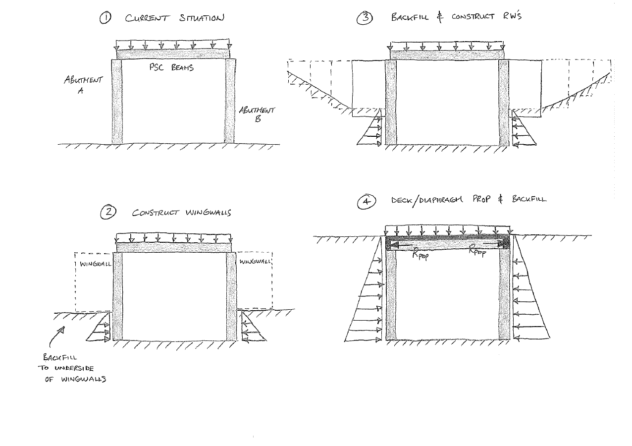
Anyway, I am going to attemp to get a little technical now with regards to the design. At present we are still constructing the inner portions of the deflection walls that butt up against the abutment wall and once we complete these we can then start to backfill material behind them. Depending on the concrete test results we are looking at about 4 days from finishing the walls before we have enough strength so that we can backfill. By staggering the work we can be working on one side while the other is curing and then backfill the first side while the other is curing. The bridge is designed as a propped structure which means we can not backfill the entire height of either abutment until the deck/diaphragm is cast, this then ‘props’ the abutments apart which reduces the bending length of the wall. We can backfill to the underside of the wingwalls without casting the deck slab but once we have backfilled we can then erect scaffolding on either side to access the deck while simultaneously working on the wingwalls. Once the wingwalls are complete we could backfill at a certain batter from the underside of the wingwalls out so that we (structures team) are conducting detailed excavation only of compacted fill for the subsequent retaining walls. This would add a surcharge onto the earthe pressure load although the backfill heigt is not going past the underside of wingwall height, so it may be sensible to cast the deck before doing so. Hopefully the below sketches explain where I probably haven’t:
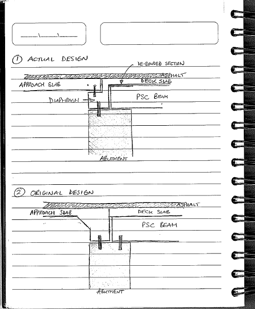
I noticed in the design report for Dickson Rd that the end dowel joint arrangement was different from the AFC drawings and so enquired to the designer about why. He pointed me towards Eastwood Rd design report which has the same diaphragm/deck detail. The original design was for the PSC beams to have a slot for the abutment dowels to sit into with rubber spacer rings around the dowels to allow for movement. The dowels restrain the deck laterally and longitudinally and what I can figure out is that there seemed to be a concern over the combined effects of flexural bending and shear on the dowels. This seems to be why they repositioned the dowels to the rear of the bearing strip and out of the PSC beams. The debonded area at the end of the beams and the 50mm gap between beam and diaphragm means the beams can flex with minimal transference to the dowels. Consequently the rubber spacers have been omitted and a PVC conduit is placed over the dowel with a snug fit to ensure debonding and so taking away any torsional actions that could occur on the dowels.
The past week with the rain has mainly been spent on catching up on QA paperwork and the laborious task of uploading ridiculous amounts of paperwork for eack worklot onto the JH project pack system. I have also spent a great deal of time both work and weekend getting amonst the costing procedures I need to fully understand before next week when I will be the sole engineer on the section. My new responsibilities will include the costing of all four bridges which equate to about 62 cost codes – 15 on Dickson Rd which are all active but quite a few on the other bridges now not. The end of the month comes at about the 15th oddly enough and the forecast comes out a week after. For that missing week when dockets and invoices are not processed by the commercial team I am required to accrue work I know has been done and estimate what I think we will do until the actual end of month including what work the subcontractors may claim for so that JHG can put that money aside in their current account and keep the rest in their savings account! Invariably the estimate is not perfect and so next month you will have to place in the correct figures aginst your estimate. A week before the end of the month the forecast spreadsheets are published by the commercial team usually on a thu evening and by mon morning all Senior Project Engineer’s and me are required to submit their forecasts which shows all cost codes for all the bridges and make that it all adds up. A large part of this and what the Construction Manager is interested in is the cost at completion forecast. If any single cost code varies +/- by $5000 then you are required to explain why and I then produce a summary sheet for each bridge so he can see what state they in! Thi is also the time to ask for the budget to increase if you needed which is what we have had to do mainly because of the very low budget for craneage that was initially set aside at tender. It took me all fri to complete 5 cost codes and sat to do another 5 this month so I am not sure how next month will go considering I will have all 62 to do. Despite the extra work load I have found it surprisingly enjoyable intermingled with massive frustration when things don’t add up but I already feel like I have a very good understanding of costs related to the work I am doing and it has meant I have had to dive into alot of sub-contracts looking for rates which again is improving my contractual understanding. One thing I did pick up from the FRP subcontract is that the deflection walls have not been priced this has been forecast. I estimated the additional cost in the region of $150,000 but I am not entirely sure the subby knows that this work has not been included. Apparently it was not included in Eastwood Rd either and they have claimed for all their contract work but have mentioned nothing about the deflection walls. It will be interestig to see n a few months time whether they do realise as the commercial manager seems to think they haven’t got a clue and is secretly hoping to pocket a few hundred grand – it will certainly make my costing reports look very healthy if they don’t!
