It’s Getting Hot In Here…
Things have really gone up a gear in the last month and as the Minox B Blower installation date draws closer I feel more and more like the BP SPA and less like the Royal Engineer on Secondment. This can only be a good thing given the circumstances.
Minox B Blower
The Minox materials left the beach on Monday, over a week after the planned departure date due to this wonderful weather restricting shipping in the North Sea. The materials were due to arrive on the Clair today, however the weather again has me at its mercy. I have high hopes that the material will be unloaded on Friday, but it really is in the lap on the gods on that front. My first vendor mobilises early next week and while they don’t require any of the materials, 6 Feb is my redline after which things are going to start to get interesting.
The project has skirted closely around failure over the last 2 months, with the closest being the HVAC vendor feeding back on their own (2 year old) designs, 6 weeks before offshore execute, that they were not fit for purpose. The crux of the matter was that in a previous incarnation of this project, the vendor had planned to upgrade the condenser, evaporator and compressor on an HVAC system (6kW to 12kW), without upgrading the coolant lines. A suitably chastised vendor went away over Christmas and came back with an up-reved workpack for the 4th of January concluding that a two day extension to their mobilization would allow them to upgrade all of the existing lines (about 50 m worth). It doesn’t sound much here, but it was a minefield of stakeholder management at the time. In the end, the asset had no issue with swallowing the extra days and the requirement for hotworks to braze the lines. The original plan to use a weldless connection technique was deemed not ideal given the number of connections that would have to be made with the new scope.
Following that was the news that one of the nitrogen lines on the current blower had sprung a leak leaving the area out of bounds to all personnel. Again, I spent time understanding the scope of the issue and discussing it with the appropriate stakeholders and due to the leak being more of a seep, the restrictions within the area have been lifted from my team. Part of this is due to the fact that the installation of the Minox B Blower addresses one of the platforms key vulnerabilities. At present the A blower is on 100% duty with no standby to deoxygenate seawater for injection into the reservoir. Without it production falls off a cliff. With this in mind, the asset is willing to take a little risk on getting the B Blower installed, and anyway, whats a little nitrogen going to do…
So thats Minox in a nutshell.
HP Cooler
Following on from the fun and games I had last year with the Clair Coolers replacement, I am the SPA for replacing the HP cooler. This scope is in Define and I have been responsible for putting together the £1.5m of funding to get it installed. One of the key issues that I have been driving is that of defining the project drivers. The original coolers were replaced due to a vulnerability in the process used to weld the tubes into the tubesheets, essentially the fabricator had skipped a step and failed to add galvanic protection to the shell side of the tube sheet.
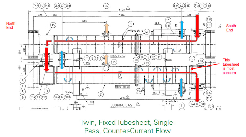
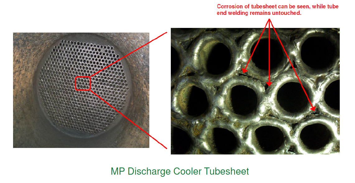
Given that the shell sees thousands of litres of hot sea water a day, and the designs allowed for an area of relatively undisturbed flow around the junction between some of the tubes and the tubesheet allowing carbonic acid to form, it was only ever a matter of time before corrosion ate through the HP/LP interface. This issue is a key driver for the installation of the HP cooler as the same fabricator and QA procedures were responsible for its commissioning. However the situation at the HP cooler is subtly different with the shell geometry being different, with far less undisturbed coolant flow and the tube side flow being effectively dry, so little or no risk of H2S drop out and corrosion on the tube side. While the failure of the HP cooler is fairly certain, the difficult question is what the time frame is. If it is less than 5 years, then there is a huge driver for this project to be complete in time for the 2015 Turn Around, a planned shut down of the asset. I am keeping a close handle on this issue, but there are a couple of other stakeholders who I am working closely with to ensure that this issue is brought home sooner rather than later.
The other issue that I am dealing with on this scope is the question of tube rupture. There exists a deficiency in the design of relief systems for HP/LP interfaces across the North Sea, mainly due to the lack of understanding of this issue when most of these systems were designed. I am quite lucky to be right at the forefront of this research with this project, playing a direct part in how the issue gets resolved for the HP cooler scope. A shell and tube heat exchanger typically has a hot medium under high pressure running tube side and colder lower pressure medium running shell side. Should catastrophic failure of a tube occur, computer modelling shows a transient pressure spike based on the interaction between the high and low pressure mediums that reverberates around the shell effectively magnifying the initial effect. This pressure wave then propogates away through whatever route it can find. Because this near instantaneous interaction between the two medium has never been fully understood until now, the relief mechanisms built into these systems are underspecce’d. In the case of the HP cooler, the BP discipline engineer I have been working with has had to take his analysis right to the limit of the ASME codes and the relief line still falls below unity at the elbows.
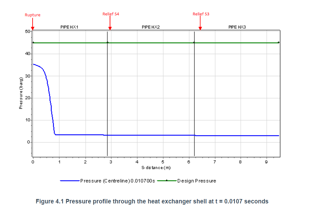
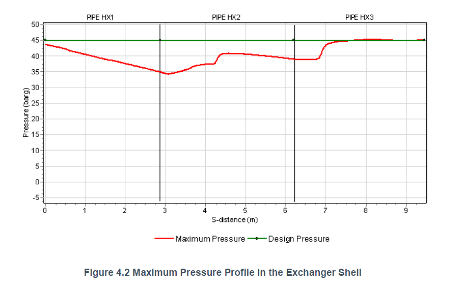
Effectively, if one of these events occurs, the pressure wave would take pretty much every part of the system, for a radius of several meters, up to the limit of its test pressure, with the exception of the relief elbows which would be taken just beyond. This potentially gives me a specification for the redesign of these elbows within the HP cooler scope, but it is a huge judgement call on the part of BP with the only real mitigation being that the chances of it happening are very remote. Sadly most of this information has come to a head in the last week or so, a missed TMR for sure unless Bren or Nick want to give it a bash.
Flowline Bracing
This job just seems insignificant in comparison to the other two, but I am really keen to get it sorted before I leave BP. It is scheduled for a May execute, although the project itself has been in offshore execute for almost 2 years now. I now have a WGPSN engineer assigned to it and so things are moving in the right direction. The thing I am most chuffed about is picking up on a potential flaw in the design. To put the new steel bracing in the project is replacing some temperature transmitter assemblies, the originals have an effective length of 100mm and the new ones 200mm and they support a 1kg transmitter at the end. Basically a 0.5″ threaded tube cantilevered out from a thermowell on the horizontal axis with a 1kg lump at the free end.
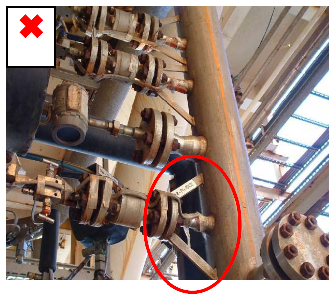
The feature directly above the red circle is the situation I have, a metal can on the end of a strut, although in my case the strut is being modified to be double this length.
I put in a query to the instrumentation engineer who specified the new assembly as to what guarantee there was that the new assembly would with stand the doubling of the moment around the thermowell and any vibrational effects from the line to which it is to be attached. The response was not a great one, I have my fingers crossed that this is not a show stopper and while I have a feeling that the assembly is probably good for the increase in moment, I am not so sure about the vibrational effects. I will be disappointed if this project gets kicked into the long grass again.

This is the kind of solution I am expecting, of course rotated though 90 degrees.
In other news
There is more, but I think I will have to save it for the next post as it is late and you are probably bored (well done for getting this far though).
Corine is quite big now (possibly a surprise to you, but number 2 is due in 8 weeks, a girl), but is soldiering on regardless. I have some hard deadlines to hit for my thesis so that it is mostly in the bag by the time she arrives. Mostly for this reason, all extra curricular activities are on hold.
I am concious that I have not included any pictures in this post, mostly because I am writing on my PC and not the work laptop where I keep all of the ‘cool’ stuff. So as a reward for getting this far, here is some more Dilbert for you. He really does keep me going some days…


You don’t sound much like a Royal Engineer either, I think in future I’m just going to have to skip to ‘in other news’ because not much of that made sense to a simpleton like me.
I’ve added some more pictures for you Rich…
All good stuff Imran (and I appreciate the pictures too). It’s at times like now (especially with your impending change in domestic circumstances) you need to remind yourself who you really do work for adn what the aim of you being there is. Whilst I’m confident you have it all in hand you may need to remind Peter and Tom that you have a course to complete too.
Looking at your picture showing the ‘as it is’ condition I wonder if you have a row of thermotransmitters above one another if you might simply brace out the top one and then connect them together, possibly also brace the bottom one or simply brace the middle… ie.. not necessary to brace all just enough to allow them to support one another rather like a terrace of houses…
RIchard, the photo is generic to illustrate the typical loading for the transmitter strut. I don’t have a photo of the actual transmitter assembly, but it is isolated, so there is just the one to stabilise.
At this stage I am keen to avoid additions to the work scope unless there is a clear risk to safety. A quick estimate on the engineering work puts it in the tens of thousands due simply to the time writing costs of getting it organised, even though the actual engineering is really quite straightforward. In terms of time, cost and quality I am erring on the side of time until I get a definite call from the asset instrumentation engineer on what he wants. The real problem with all of this is that BP did not properly define the problem to WGPSN when this originally came about and so the solution that has been presented is not fit for purpose and requiring all of this last minute work. Luckily I am more than £40k under budget, so at least that is not an issue yet.
Congrats on the second kid mate, when is she due. We are expecting our second as well, a boy due 7th May. John Bainger needs to get a grip and get a 2nd on the go. The less said about Westy the better.
We appear to working to a similar time table, she is due on 27 Mar! Hopefully she is going to arrive with a completed thesis in one hand, beyond that I just hope she is healthy!! Can’t be too hard on Westy, I am sure Nik has it all planned out for him.