Archive
R+R
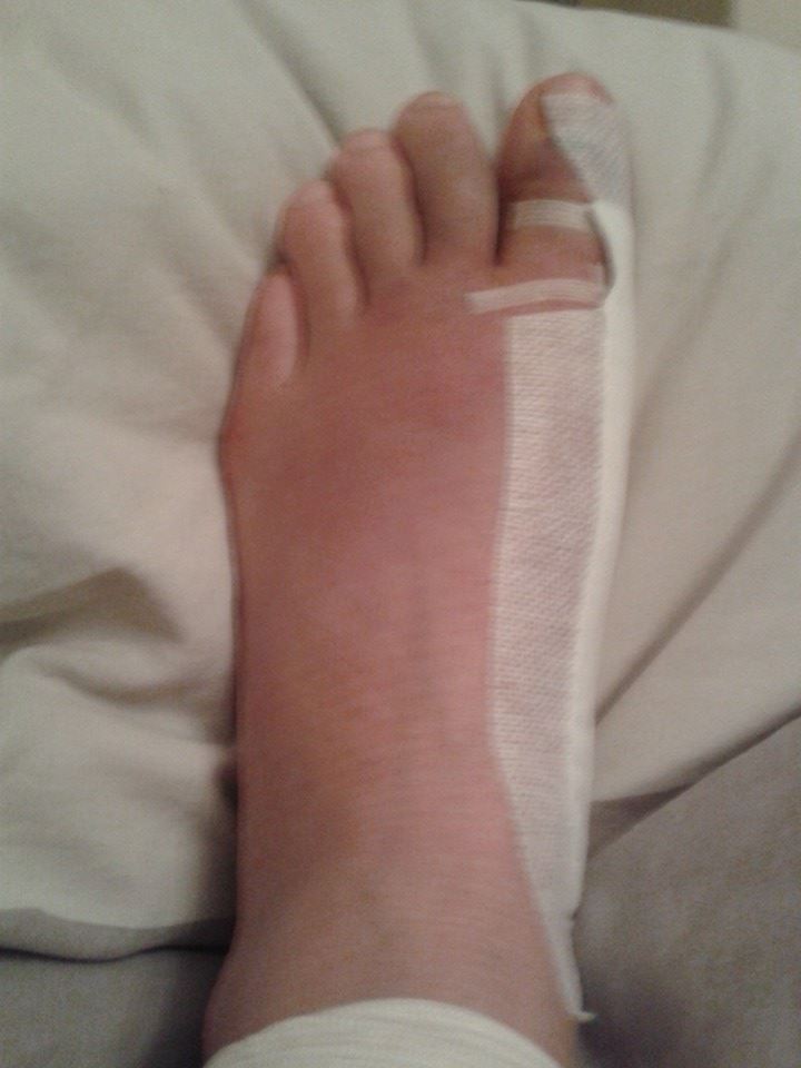
Well I haven’t blogged for a while as I have been at home feeling sorry for myself after my other foot operation. I have now progressed from crawling and hopping to now hobbling around the flat and I am being a bit more productive. The first week involved co-codamol induced tiredness and my foot feeling like it was full of molten lava so I didn’t achieve very much except a few odd jobs and lots of watching Grand Designs, Homes Under the Hammer and Building the Dream. Just to prove I haven’t been off skiving here is the foot after a week:
My highlights of the week were the arrival of the postmen and Ocado delivery guy. One of which bought me a very exciting get well present from a friend. Helping to maintain my engineering practical skills and entertaining me for 2 evenings and 1 morning, I give you the Lego Campervan:

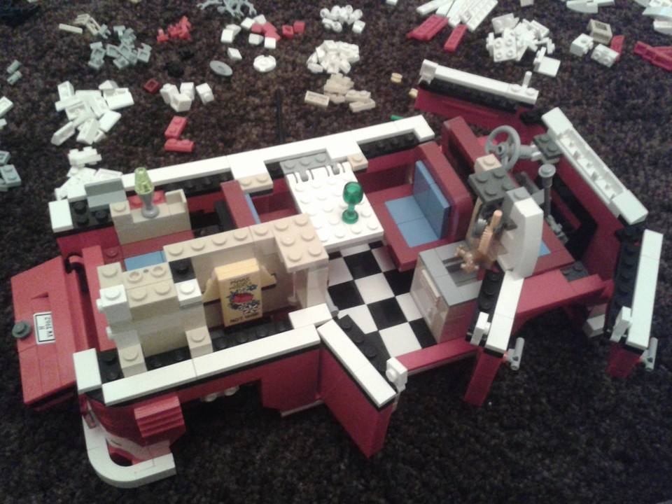

Hours of entertainment and great attention to detail inside it. I am glad the age was 16+ as I was surprised how long it took me! The engineering challenges were organising my stores area without taking up my whole living room and not lifting it up by the roof which falls off under its self-weight!
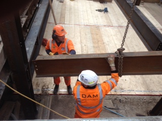
I have also been keeping an eye on my Carillion emails and it doesn’t seem like I am missing anything too critical. The most exciting email has been regarding the banana shaped HV slab. The plan was to knock the wall to Battersea Park Road down, install a GRP housing on the slab for the substation, insert the substation equipment into the housing and connect the cables. However, the Battersea Power Station Development Company (BPSDC) who are the client have been unable to knock down the wall as TFL will not let them close the footpath. The doors of the GRP to the substation were meant to open outwards to where the wall was but seeing as it is still there the plan had to change. Scottish and Southern Electric (SSE) have now decided to get a different GRP housing which has 2 sets of doors on each side. It sounded like a good plan until I read the next email which said that the housing was bigger and would overlap the slab by 400mm! So the client has requested that Carillion extend the slab to fill the void. It sounds like it is going to be a time consuming and expensive work around for not being able to knock a wall down when expected.
Tomorrow I am back off to hospital for my X-rays and hopefully I will be off crutches by the end of the week. If all is well then I will be back to London on Sunday to go back to work on Monday. It will probably be another 3 weeks before U can get my work boots back on so I will be confined to the office for a while. I hope to do a bit of talking to the H&S manager and the Environmental and Sustainability person. I might also try and get a day shadowing the Temporary Works Designer for Carillion who works at their main office. Are there any other useful things I can be getting on with before they pile my desk with paperwork and tasks that nobody else wants to do?
Conveyor 620 continues.
Blog No.3
My work continues along conveyor 620 and I am now following a fairly set process to complete the different foundations.
My last blog concluded with the piling almost complete (6x steel still to be driven) and preparation for the next stage of the foundation construction. So if I explain what I have done for Transfer Tower (TT)615 the process for all the other bases is more or less the same.
So initially I set the pile cut off point at 50mm (cover) below the finished top of concrete (TOC) level and cut the piles.
By extrapolating the information from the foundation GA drawing I set the level of the shallowest element (the 300mm main slab) included 50mm for the blinding, and excavated the entire base to that depth. This included 800mm of additional horizontal space around the outer edges for the shuttering to be subsequently placed. Once this initial excavation depth had been dug I then set out the slab ground beam locations and services that required further excavation (usually 500mm – 1000mm depth from TOC) , again including 50mm for the blinding. Once excavated the bases look something like this.
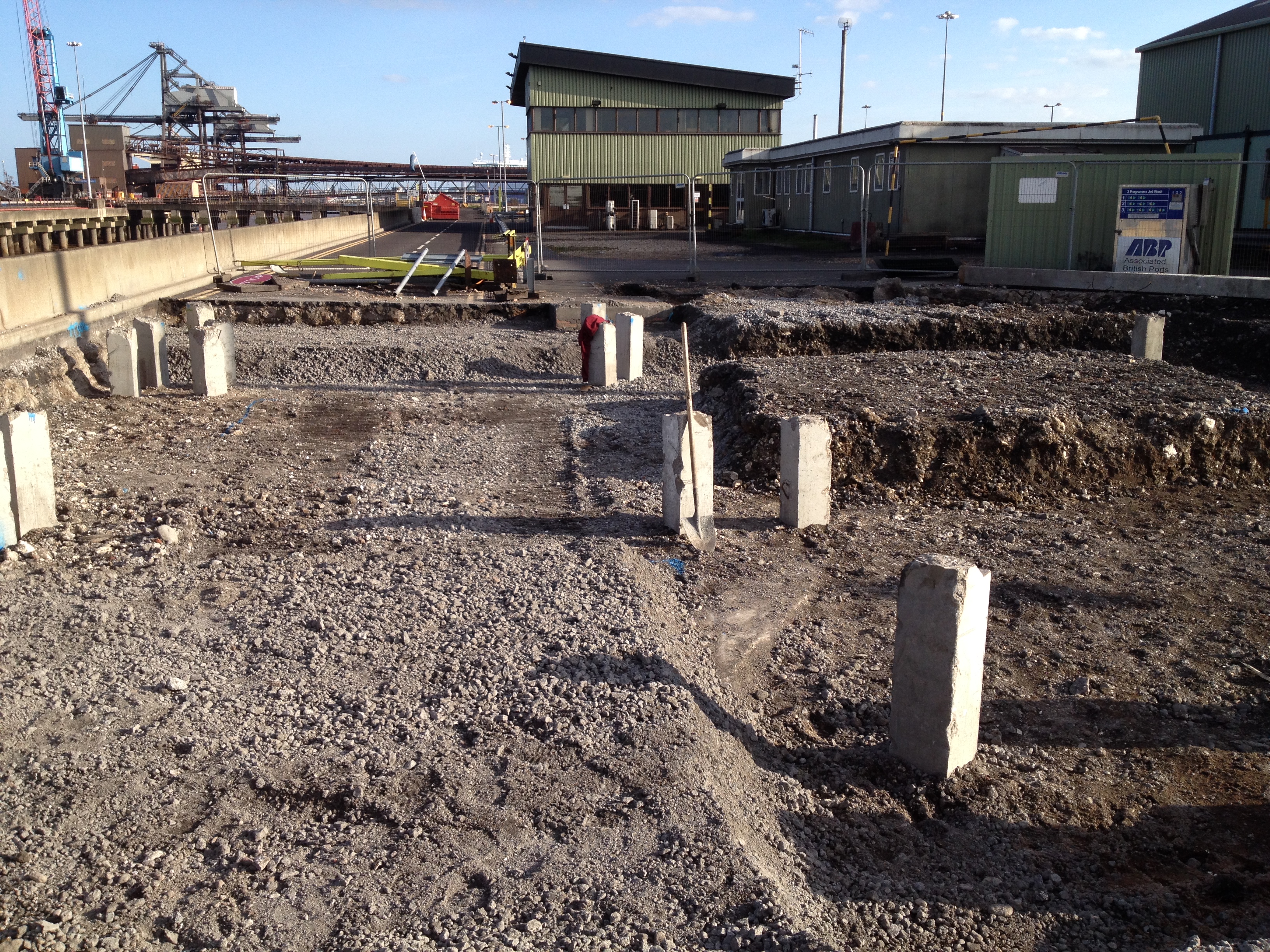
TT535 piles cut 50mm below TOC, excavation complete for slabs and beams.
I then cubed up the foundation, ordered and placed the 50mm blinding layer. Semi dry concrete was used to grade the slopes from the ground beams to the slab locations.
Once the blinding cured I set the level for the piles to be crunched and the steel exposed (usually 75mm above the blinding as the bottom cover is 75mm) and the rebar was then broken out. Once the steel was exposed the electrical subcontractor came in and placed all the earthing cables, welded to the pile rebar.
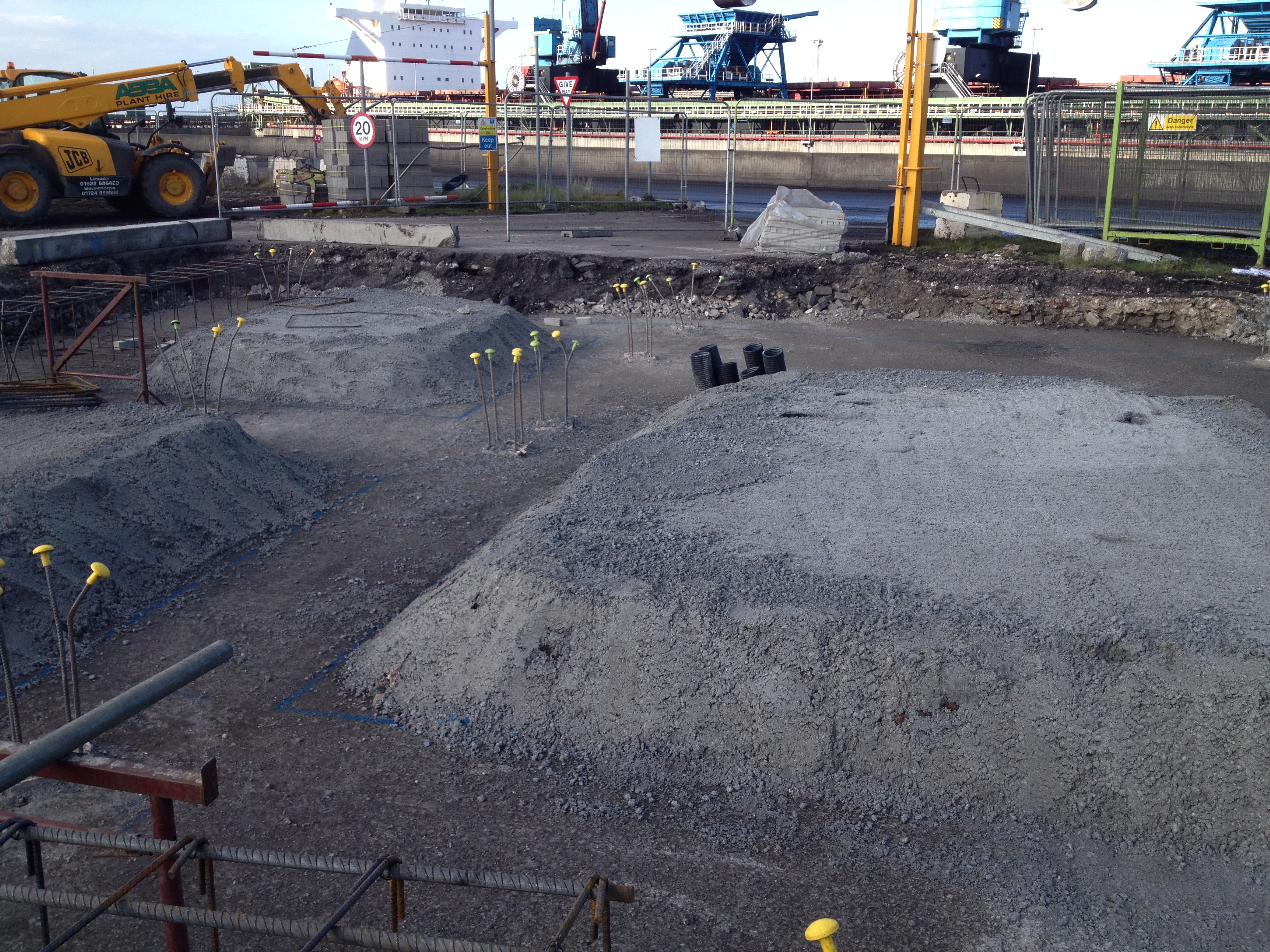
TT615 service pipes placed, blinding poured, slopes graded, piles crunched to expose rebar.
Using a total station I set out the extremities of the foundation, placed the nails, strung out the edges and sprayed the lines for the steel fixers.
The fixers then arrived and started positioning the steel reinforcing and I was checking the configuration, cover and heights.
The joiners placed the shuttering around the steel and again I checked the alignment and cover. Once the main body of the steel was completed I set out the positions for the starter bars for the various upstands and walls that come out of the foundation. These starter bars still need to be placed and the next stage will be to place the bolts for the structural steel, prior to pouring.
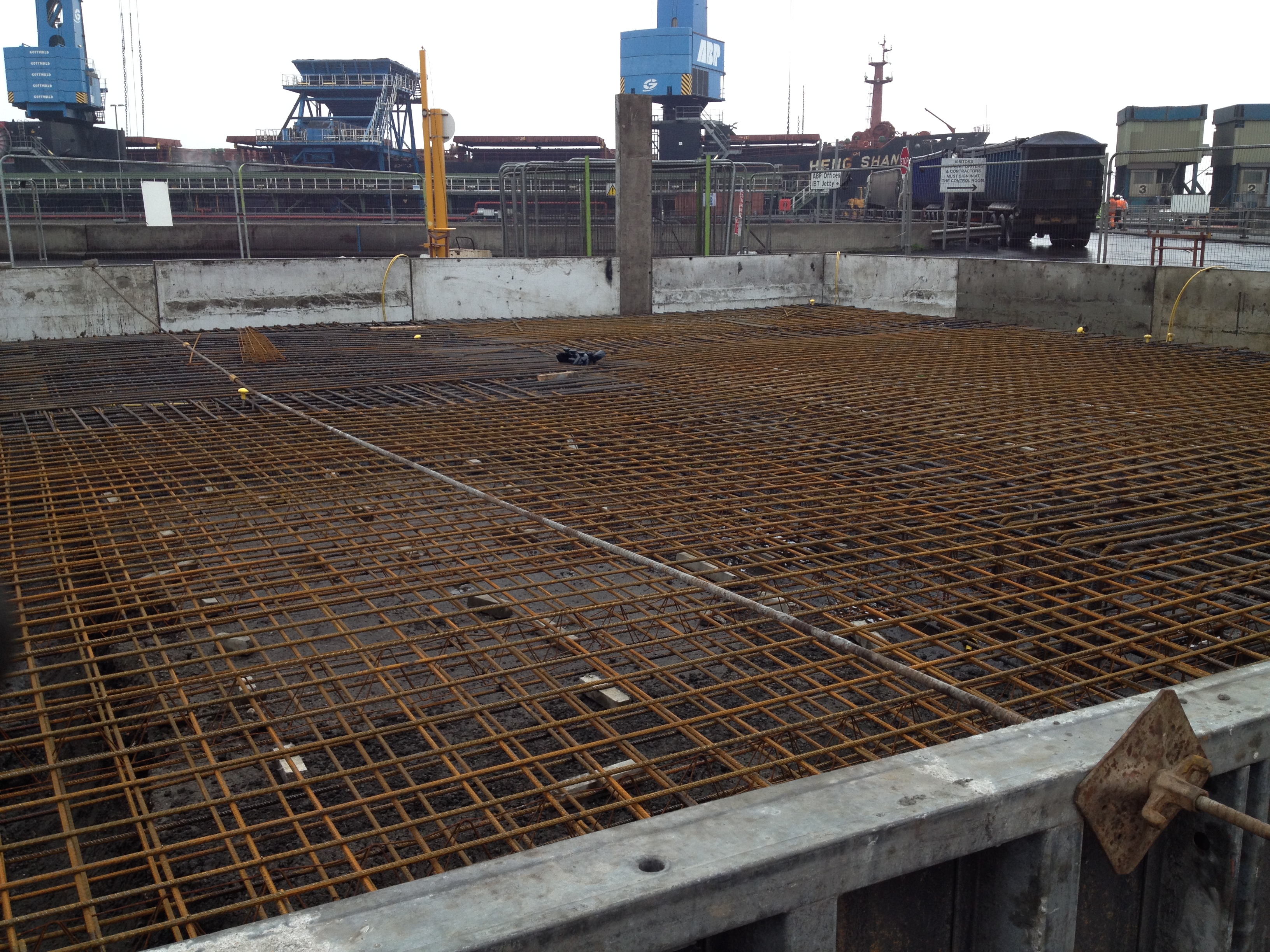
TT615 steel and shuttering in place. Starter bar locations for upstands and walls marked out.
This was the process I conducted for TT615. TT535 is awaiting the steel fixers and I am overseeing the excavation of Trestle 2-4 and the GTU as I write. It’s now a case of keeping the process up and ensuring I am 1-2 days ahead of the various teams of labourers, fixers and joiners spread across my section of work.
Reflections.
Services. The drawings do not include all of the services that may need to go into the foundation. I have only been caught short once where 6 service ducts needed to be placed into one of the bases and were not included in the GA. Luckily this did not require much remedial action and I discovered the omission before the blinding was poured (just). I did lose one of the smaller pads I had left for the construction of the slabs as the services went through it, but the fixers managed to make some steel chairs to support the slab steel as it was only a small area. Cleary this has a small cost implication as the ‘void’ will now have to be filled with structural concrete but as we are talking probably 1m3 I’m sure it will not be a problem when we come to pour.
Even when I found the drawing for the service ducts and was about to start the excavation I double checked with the electrical sub-contractor that it was in the right place. He agreed it was coming through the slab in the right place but the proposed alignment was incorrect. He then produced version A of the GA drawing (I was on G) and asked me to realign the proposed route as the electrical services had been designed to his drawing. On this occasion it did not significantly alter things but apparently this has happened on several occasions, with different drawing versions creating confusion and additional work. I now ensure that I communicate with all the service stakeholders prior to any excavation.
Speed and Accuracy. It surprised me just how quickly on completion of the blinding the steel fixers were all over the first base I had prepared. Having managed to place the blinding a day ahead of schedule I thought I had bought myself a little breathing time but I think everyone else thought the same. I set the nails and sprayed the extremities of the foundation and the fixers were on the slab before the paint was dry! I had a concern about 2 of the points appearing to be not quite square (on confirmation of the positions with a tape) and so queried the off sets on the GA. By the time the error was confirmed and I had the opportunity to re-shoot the positions the steel had been placed and the shuttering was being positioned. I spoke to the foreman in charge of the joiners and pointed out the adjustment required but as a couple of the holes for the shuttering had already been drilled in the blinding they simply ignored the new position and cracked on anyway.
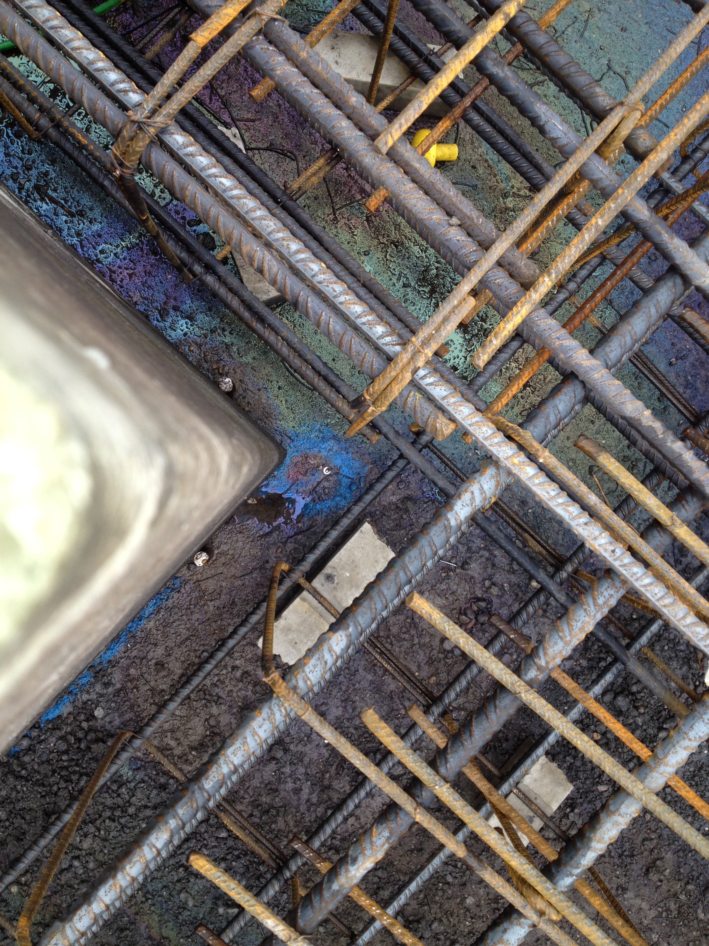
Shuttering and steel out of position.
This left an approx 30mm extension in the base. I was not overly concerned as the cover was still sufficient, the alignment still straight and the edge did not tie into another structure. I highlighted the issue to the section manager who agreed with me and did not see it as an issue. What did surprise me was the lack of care shown by the joiners. The issue was highlighted in good time for them to only have to conduct 5-10mins remedial work. By the time the section manager had seen it, if he had decided that it needed changing the amount of remedial work required had significantly increased as all the shuttering was in place. Perhaps the joiners experience led them to know what would need changing and what wouldn’t but I’m not sure they have ever heard of the phrase ‘a stitch in time saves nine’. The experience has led me to be extra cautious when studying the GA’s. In this case it was difficult to see the error prior to them being set out and due to the speed of the follow up activities after marking out the foundation it proved difficult to actually prevent the subsequent errors. It subsequently took me half a day to set out the dozen or so nails for TT535 as I wanted to be 100% confident in the positioning after this experience.
Responsibility. The original section manager I was working to has moved to another site. This has prompted a reshuffle in the section, where the previous section engineer has moved up to section manager and one of the site engineers has moved up to section engineer. That has left 2 site engineers responsible for all the work across the site (bar the silos). Last week the other site engineer was covering a night shift as the steel subcontractor is significantly behind schedule and having to make up the time. This quickly left me as the only engineer in the section and although the section engineer was mucking in I found a lot of extra work on my plate and have now been overseeing the construction of another substation that I may blog about in the future.
The Misery Line
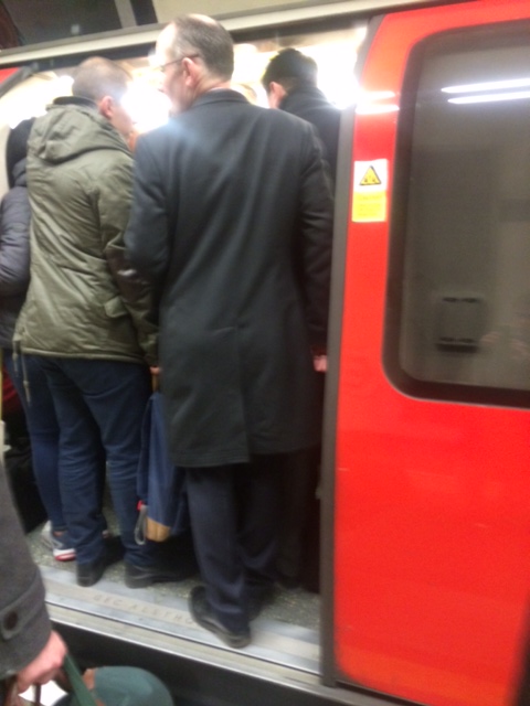
Also known as the Northern Line!!!
For those of you in London
This is what a morning commute in the New Forest looks like. No fat sweaty blokes on tubes here.

Opps it don’t fit!
This week I have been treated to a short city break to Birmingham to attend the in house 3 day Lain O’Rourke surveying course. The course was an excellent opportunity to brush up on surveying knowledge and proved to be more challenging then I first thought and it has helped to cement in my mind that surveying needs to be taught over a greater period then is afforded to Margret and her team in the PET course programme. Whilst much of the theory is understood by many on the course the practical application and use of a total station is a little less well understood. I would even go as far to say non existent as I struggled to find the big red on button on the latest version of the Leica total stations we were using. Having found the on button and now successfully navigated myself around the menu system I feel a little more confident in the use of a total station but a skill I fear will easily be lost if not put to use fairly quickly.
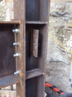
On returning to Liverpool street on Thursday I was faced with an issue of buildabiltiy. A steel structure designed to be robust and provide protection to personnel operating within its perimeter from incensed plant operators swing excavator buckets about was in fact so robust it couldn’t be built……..WTF. It had only taken 3 months to complete the designs and have it specially fabricated by a steel structures specialist and now we were going to be defeated by our own designs.
The issue was that were two I beams connected one end plate to another’s flange the designer had incorporated two web stiffeners top and bottom. This then prevented the perpendicular I beam from being lowered into position by the web stiffener. A morning of discussions ensued during which it was discussed about removing the top stiffener and replacing it, or completely removing it. Given that the purpose of the web stiffener in is to stiffen the web against buckling due to the compression of the flange and that in this case both web stiffeners would be required. The real issue was that the detailed calcs that supported the design were less detailed than one of my design exercise calcs and no one could seem to agree on the loading that the structure would have to resist, both permanent, imposed and accidental. Prophesising over all likely laods was brought to an abrupt halt as I gazed out of the window to watch the sub contractor bending one of the columns over to allow the beam to fit. Given that time was/is against us the requirement of the web stiffener suddenly became less of an issue and we turned our attention to managing the problem, and if I remember my lecture with the great orator this could have been avoided had we managed the engineering at the start. Your thoughts please.

Radon and Snow???
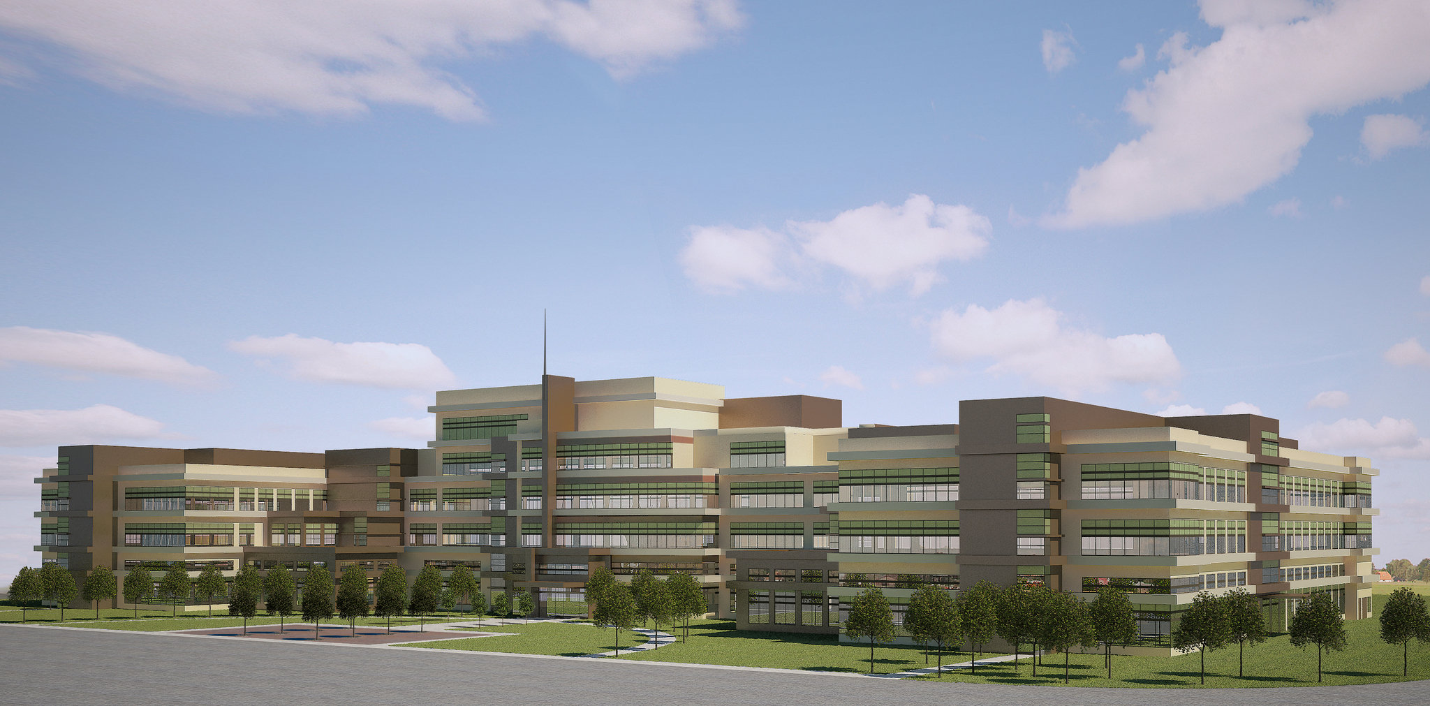
My primary project is the construction of a Headquarters Building for the US Defence Logistics Agency – a $81 million project that should be complete Oct 15. Artistic overview below:
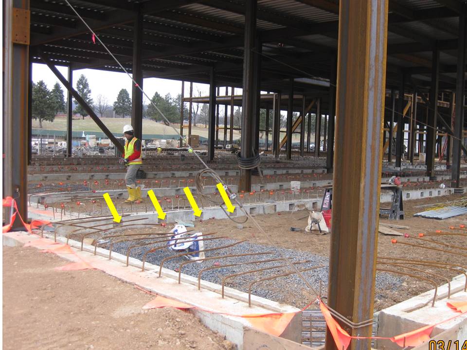
An interesting point to blog-share….Radon…??? I was curious as to what the holes indicated by the yellow arrows were? Well, they are to allow for the spread and extraction of radon across the area beneath the concrete floors. Radon is a natural occurring gas that is radioactive and causes the highest number of lung cancer cases in the USA amongst non-smokers. Little did I know, but the Pennsylvania area (Appalachians) has the one of the highest concentrations of radon in the USA. You will note an aggregate bed – this is approx. 0.2m thick upon which the non-structural concrete floor is laid; the compacted aggregate provides a bed upon which to lay the concrete floor but also a permeable band for the radon to move through.
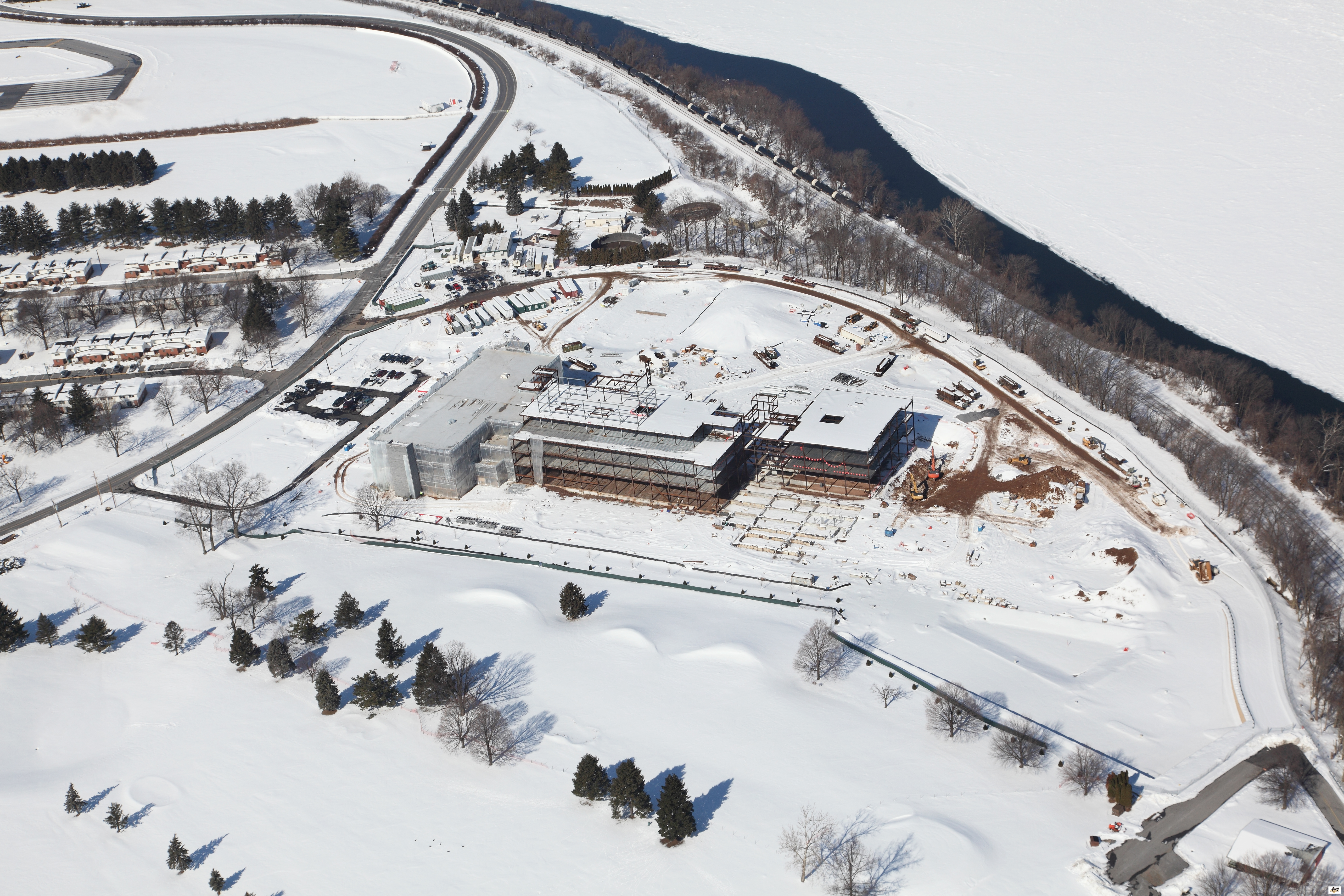
Weather has been a major issue with progress – one has to approach a problem differently in these climates. Despite local advice, the contractors cracked on with completing all the steel for the entire building – made sense from their point of view as its easy to continue one thing whilst you’re on a roll and all equip is on site. The problem now is that none of the concrete can be laid, particularly inside the building as it is too cold. To expand on this: there has only been 5 days since the end of November where temps have been above 5 deg C…the min temp needed to apparently maintain satisfactory curing. Our advice was to put up steel in one segment of the building; clad in the precast concrete walls in order to allow them to have an enclosed space to heat easily, where stairwells and flooring could then be poured. Instead contractors are making the best of a bad situation and installing M&E in as much of the building as possible. The photo below shows the site last month….it looks exactly the same this afternoon as another bout passes through!
I got some arrow the wrong way around!
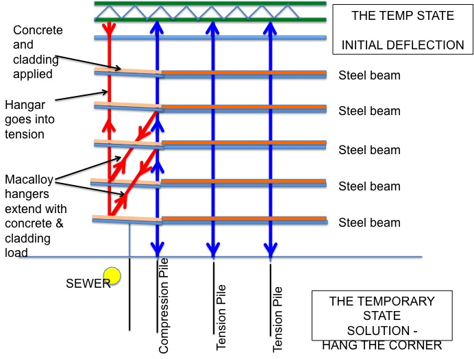
On closer analysis and a good think (and remember to being on site) I have realised I over-simplified the problem at 5 Broadgate with the Macalloy hangers.
Here is effort number two. The main changes being that the Macalloys are used to pre camber the steels prior to the concrete being poured. On pouring the concrete the hangers & truss will deflect (deflection 1). The Macalloy is then released and the decks deflect further (deflection 2). Ballast would additionally be loaded onto the corner to represent cladding (deflection 3). At this point the final deflection is realised in the hanger & truss. This means that as a piece of cladding is installed on the exterior, ballast inside is removed (deflection 3 + cladding – ballast = deflection 3).
The reason for doing is, is because the designers did not design enough ‘play’ into the cladding. Once the final piece of glass is installed there would be not ballast inside and any live loading inside can be taken by the 15mm tolerance remaining.
Stage 1 – Pre camber the corner

Stage 2 – Pour the concrete in the rest of the building

Stage 3 – Pour concrete on corner is one day (all ten floors). Cure concrete. Release Macalloy. Load floor with ballast.
Stage 4 – Final deflection realised.

Importance of Understanding
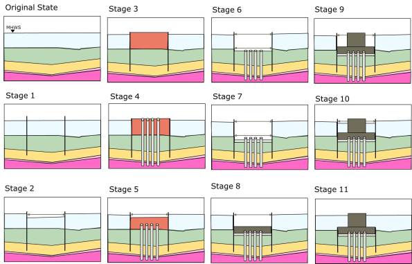
Option 2 – Cofferdam construction sequence.
The Importance of Understanding – Initial Sequence
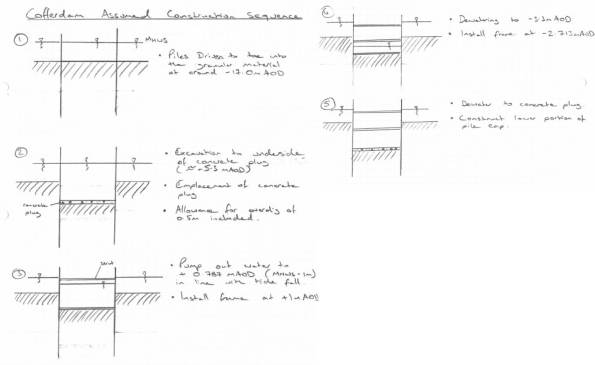
This is my initial construction sequence sketch. Sorry the sketches don’t want to embed in the document.
The Importance of Understanding
John Moran and the SI can be feeling justifiably smug right now. During both COFFERDAM and SOFT BOTTOM JM continual told us to understand the construction sequence or method statement of what we were doing before embarking on calculations. DB frequently told and re-told of how he would first spend time drawing stuff for design exercised before calculations.
I mentioned my encounter with bridge abutment design a little while ago where I picked up a slight error in my calculations in time when I realised the maximum retained height of a wall was in the temporary case during a road excavation. My point at the time was by knowing how things are actually built I didn’t publish erroneous calculations and felt quite good about my contribution, assuming that an engineer with less construction experience wouldn’t have picked it up. But my point should have been a lesson learnt, if I had thought about (and yes sketched) the construction sequence I would have picked up the issue even sooner and saved time.
I’ve previously mentioned the Barrow Bridge Tender which is a cable stayed bridge of around 1km in total length. On Monday I was tasked to answer questions on a couple of cofferdams that will be required to construct the foundations. The output is so the contractor can price an outline solution for tender purposes, the final design will fall to the temporary works designer for the project. Therefore the design needs to be economic enough to win the work but without spending too much time (and fee) on it, therefore not to Eurocode, old fashioned lumped factors of safety are the order of the day so detailed design might squeeze some savings.
One of the cofferdams will be mid-river (within the tidal range which can be used as a benefit when pumping out). The questions just wanted to know sizes of walings, props, sheets and likely toe depths. The really simplistic solution (though I don’t think even a true idiot would do this) would be to consider the whole thing wished in place props at the varying heights to ratios according to ‘h’ and produce that as the answer. This would be extremely wrong. A more sophisticated solution might be to consider the construction stages and check at each, again placing props at the recommended ratios of ‘h’. However it’s only when you consider what you’re making the cofferdam (Moran, 2012, his office with a disappointed Dad look) for that you realise that props need to accommodate the construction of the 3 metre deep pile cap and so props in the bottom of the hole are silly. It is easiest to reach all these conclusions with a pencil and a sheet of paper (Blow, 2012, tea and toast during misty eyed reminiscence). So having no idea how to construct an inter-tidal cofferdam with ‘I told you so’ echoing in stereo in my ears I picked up a pencil and sketched.
I started with the assumption that the piling and excavations would be conducted from a barge/jack up. The result is shown below.
The WALLAP analysis could then be run building each of these construction stages into the sequence. This would give me maximum BMs and SF in the sheets, and axial loads in the props. The software also gives the point at which the FOS is at a minimum which is after the water is pumped out prior to installation of the second frame so I can highlight it to the contractor. Feeling pretty please with myself I skipped along to a meeting on my own into the den of the bridges (a soul less place with engineers stacked tighter than baked beans in Tesco, I even spotted one asleep at his desk!).
My smugness was shortlived. The last time I talked about construction stages I missed the lesson, this time I didn’t. I can guess what I think might happen but the contractor has a very different plan, well 2 different plans in fact and he wants each of them sized. So this time I’ve drawn up the sketches for both options (Powerpoint beats pencils) and am seeking agreement on the sequence before doing any more numbers.
So JM and DB feel free to use me as the example of a PET student who though he knew better and Phase 1 really think about how things get built before you design them. I don’t know how relevant this is to building structures, I think it’s a little more subtle for example on site we couldn’t store a pallet of plasterboard on the floors because the design loadings were so small, they had to be split before storage.
This whole episode does again reflect on the difficulties of managing the design office environment, I was put on an element of the Barrow Bridge permanent design 4 weeks ago because there was nobody else, the Design Engineer working above me has had to return to site for 5 weeks on another bridge crossing (New Forth Crossing) and so I have become the only geotech bloke working on it. So when the extra work came in it was me to carry on, the design brief was given to me in isolation and the first chance to discuss it was during the meeting with the bridges team. Once again the matrix structure fails because people are given work because they are available. In reality there should have been yesterday’s meeting before I embarked on more detailed design, or perhaps I should have chased bridges for an outline sequence of construction?
