Archive
I designed something
It has been a few weeks since my last blog largely because I have found it hard to bring myself to again ‘tippy tap’ away on a keyboard following the delightful months of Jan and Feb report/thesis writing. Since my last blog I have gotten very little sleep because I believe my child may be possessed by the devil between the hours of 2000-0700 hrs but I have also done a few proposals and some designing finally!
Proposals/Tenders
Since starting I have been given two proposals, one for TfNSW (Transport for New South Wales) – yes the name is probably copied from London – and one for Sydney Trains. Sydney Trains are actually a entity of TfNSW but becasue they are the train service operators they do have a slightly different approach and format to proposals than if it were a new TfNSW project. Both have exposed me to the way proposals and the important lump sum fee is derived which I covered last time. Becasue I have managed both of these proposals I will PM both if we end up winning them but at present nothing has been heard which is probably not a good sign. Subsequently I am slowly being drip fed other proposals as they come up and have just completed a design services fee for a multi-storey car for an architect who has been approached by a tendering contractor for a TfNSW Design & Construct (D&C) contract. I only had a day to do this but the architect has had the proposal for a month which suggests they have probably given it out to other consultants and receievd rather shocking prices back or just wanted a fee to compare previous quotes to. Either way they seem to like it becasue another proposal came my way this morning for a similar car park – I may get branded “the car park guy” very soon! I think I covered pricing details in my last blog, needless to say it is not very scientific and involves just estimating the amount of hours you think it will take across the multiple diciplines to achieve the specified deliverables as set out by the client. The design stages seem to get named differently depending on the client but generally follow this sequence; System Definition Report (SDR (concept) – 15%) stage, Preliminarry Design Report (PDR – 50%) stage, Critical Design Report (CDR (detailed) – 90%) and then Approved For Construction (AFC) stage. Between each stage there is a least a 2-4 week review procedure with the client to get through which can take longer and is why many sub-consultants are very wary of the smaller jobs as the margins are tiny and in this business time is definitely money. Everyones hours are acconted for against a project number and every job I have come across seems to be a lump sum price. The final parts of the design stage are often in the form of construction support (answering Request For Information’s (RFI’s)) and of course As-Built or Work As Executed (WAE) documentation and drawings which formally records the changes to the original design throughout the construction process as well as confirming that the the contract has been fulfilled by the Contractor.
Eveleigh Columns
The Eveleigh MC column deterioration due to corrosion has now progressed and I have produced a reference design for the client so that a Design & Construct contract tender can be issued. As I mentioned before, it was believed that stray traction current may have been causing the corrosion. I also remember the great orator may have asked a few questions which I will endeavour to answer here. Firstly the concrete strength that I used as the basis for the original structural capcity check was low due to the variable results of core testing, I did not use a strength 1.64 dev below a mean value, I used the following equation from the Australian Standard which equates a characteristic value of a sample by taking away the (sdev of the sample x an S value) from the average. Secondly, the thought regarding the mechanism of electrolysis taking place was due to the current from the OHW finding its way back to the substation via one or both of the tracks and that the building was parallel to the tracks and I assume that the substation is also within close proximity of the building, then stray current was being conducted through the piles and columns, again I assume because this was a shorter path for the current to take therfore the reinforcemnet was acting as a cathode with the ground and the ground and piles acting as the electrolyte. In this example there is also a second case to support the stray current theory and the more likely, this is due to the OHW and tracks within the building with the current travelling down the raised track supports and through the columns in the basement to the ground. There is a couple of sketches below to try to explain this a little better or confuse you even more!

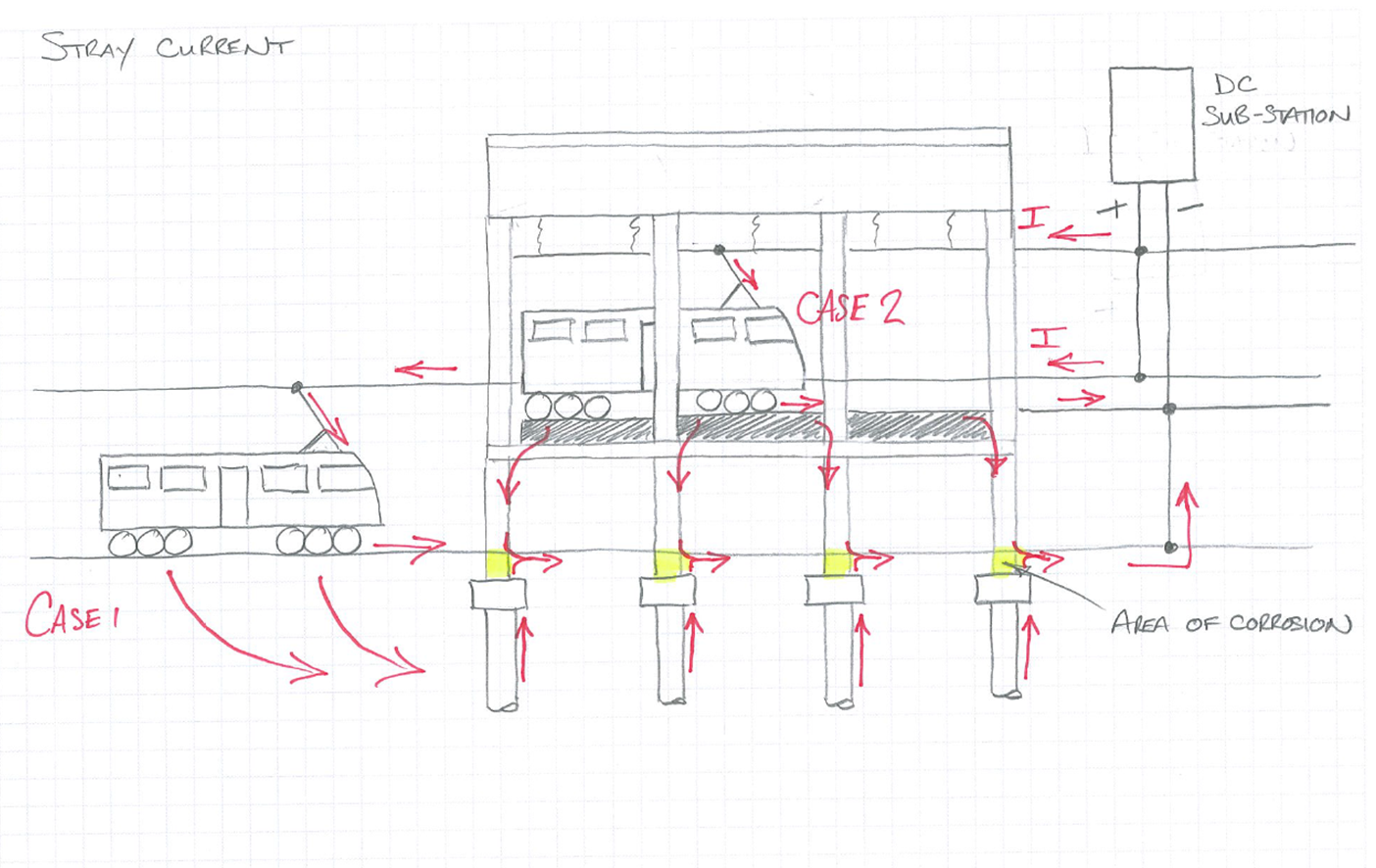
We ended up getting a sub-contrator in to measure any current flow within the columns and concluded in the end that stray current is very unlikely to be the main cause of corrosion. The fact that there is no ground slab, the basement has poor ventilation and is very hudid, as well as the quality of concrete and lack of adequate cover in places suggests these issues have accelerated carbonation attack of the concrete to the depth of the reinforcement. Chloride attack has also been ruled out from ground testing. Although it wasn’t in my scope of work I wanted to investigate the mechanism of the corrosion further which resulted in me involving other people who after a while wanted the project number to charge their time too, which was probably not expected by my manager. I think because the client has had little idea about what they want this has been a job that SMEC want to close out and move on from quickly. My investigation has determined that the likely cause is from a differential aeration corrosion cell formed between the two environments with which the column sits i.e the ground and humid basement area, coupled with poor quality porous concrete. Oxygen not only enables a corrosion reaction by maintaining a cathodic reaction, but it can promote one. This occurs where there is a difference in the
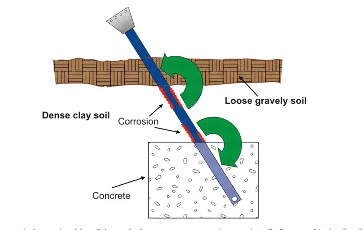
concentration of dissolved oxygen between two points of the same metal surface. Hence the poor quality of concrete has enabled oxygen to contact the reinforcement steel. The below diagram explans how a differential aeration cell works, the portion of the shaft in contact with the clay type soil acts as an anode to the portion of the shaft in contact with the looser gravely soil, which is consequently the cathode. This can be thought of as a similar scenario to the columns where differences in porosity can lead to an oxygen concentration corrosion cell:
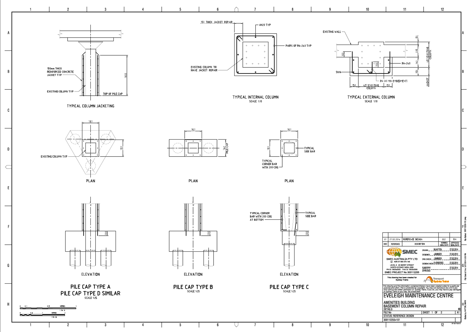
The CP option has now been discarded and the client wanted a worked up design for the repair of the columns so that they can engage contractors to price and execute the work. My solution was dependent on the severity of corrosion within the columns which we will not know until a contractor is elected to carry out the work. I then looked into treatment and patching products. I ended up modelling different levels of corrosion depending on what may be found by the initial investigation by the contrator which would then trigger a particular repair option of either localised patching or constructing a RC jacket around the column. I determined that up to 15% reinforcement section loss on either a corner or single face could be accepted before a jacket would have to be constructed, this was based on providing a further 50 year design life to the structure. An even, overall section loss throughout the column of 40% would also be acceptable but is highly unikely to occur. Any reinforcement section loss above these levels would require a jacket of concrete to be constructed around the column(s). I also had to think about the methodology and sequence of works. Having a better understanding of a contractor it would be a fair to assume they would start hacking out concrete that probably doesn’t need to be removed and more importantly would affect the structural integrity of the whole building, certainly if multiple columns are repaired simultaneously. This required a Safety In Design (SID) process to be carried out, which is pretty much just a risk assessment tool which identifies the main hazards and controls as well as the residual risk post control. In this case, measures such as temporary propping in some circumstances but prodominantly trying to eliminate the risk by only allowing a specific sequence of work to take place, so that sufficient redundancy remains within the building and ensuring the building loads do not increase – the use of the building does not change throughout the works. Below is the drawing that – along with a page of notes – accompanied the design report and performance specification (methodology):
It is a good idea to hit steel to steel connection bolts with a (small) hammer
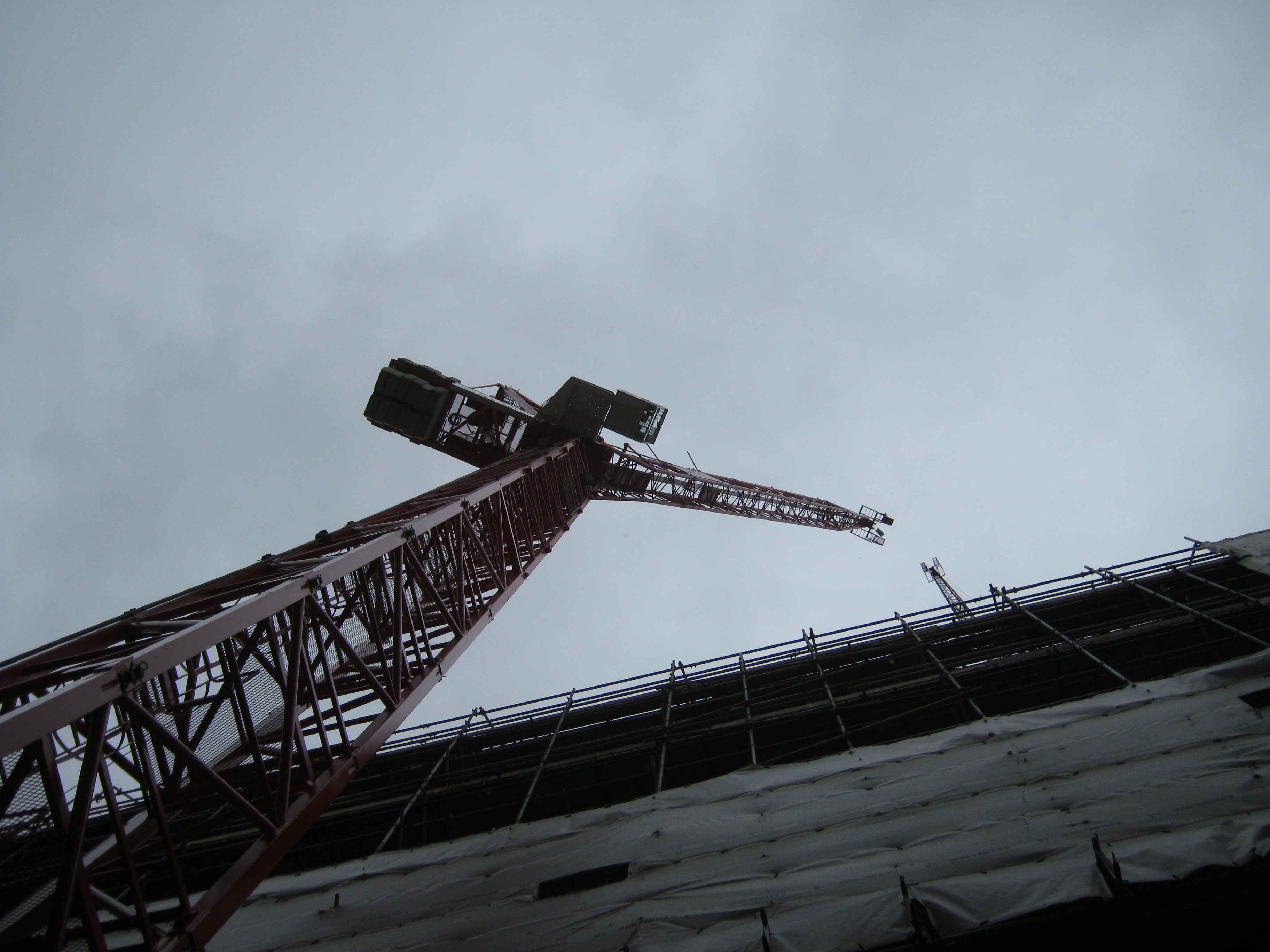
So here is a picture of Tower Crane Two (TC2). It is a WOLFF tower crane with a 45m tower and a 40m jib.
 Tall Red Crane
It was installed on Thursday and Friday last week by HTC. On Thursday morning prior to the installation I went on site with Roy (the Mace Construction Engineer) and the designer (from a consulting engineers) to sign off the grillage.
The steel grillage connects the tower crane to the piled foundations beneath. Simple right? That is what I thought. So we went on site, had a look at it and signed the paperwork after some discussion.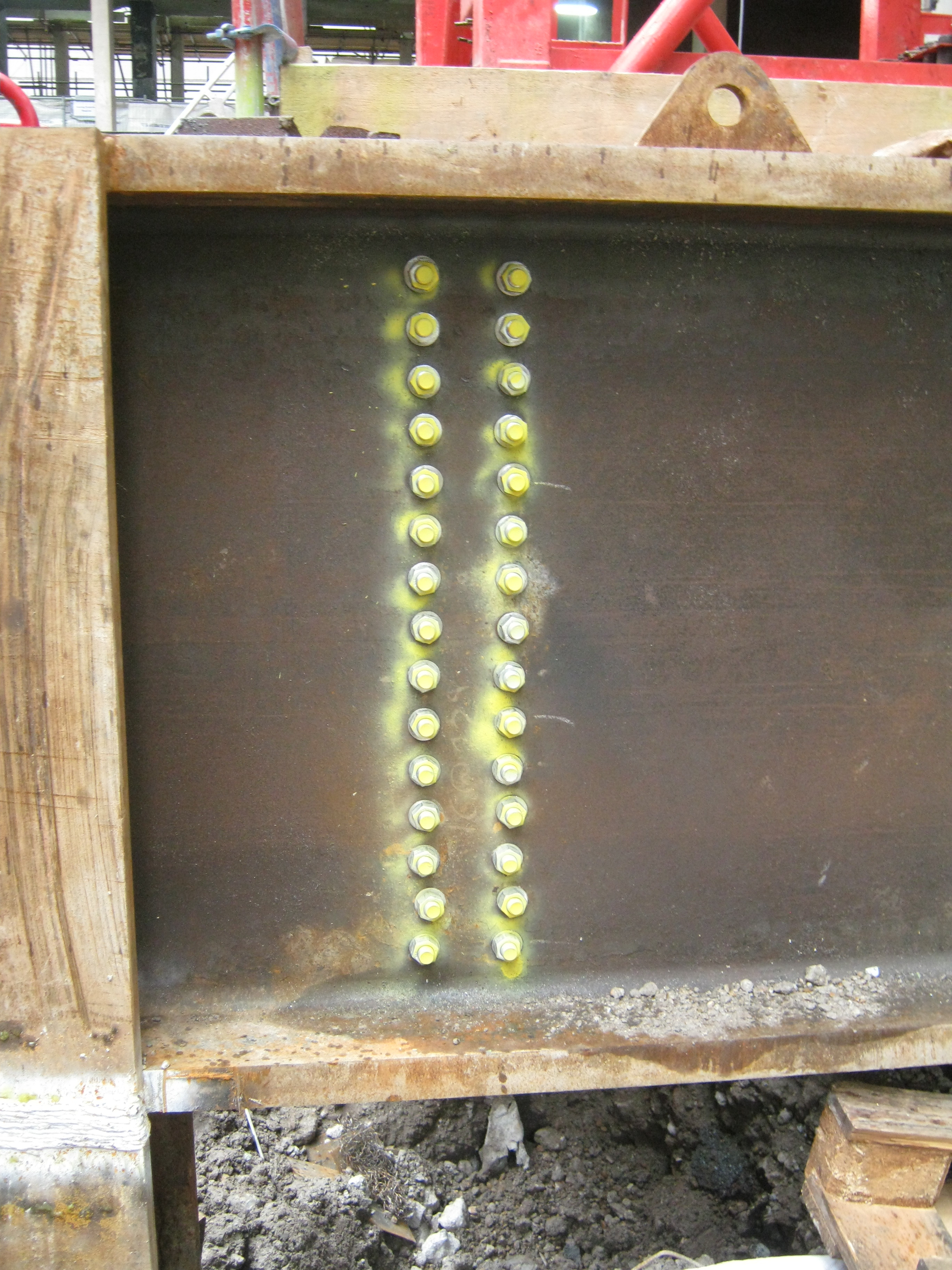
The Grillage
Well on Friday afternoon with the crane built and the load test about to start, the HTC inspector just thought he would check the bolts on the grillage (sprayed yellow in the picture above). Technically doing this was not in his remit, but he thought it wise to give them a tap with a hammer to see if they’d ‘ring’ (tight) or see whether they were loose (and don’t ring).
Well, many didn’t ‘ring’! In fact maybe 5-10 (of 240) were positively loose and perhaps 50% could be tightened further with a long spanner! Queue phone calls to the Construction Manager, Sub Contractors and me! The questions being:
1 Why are the bolts loose?
2. Who tightened the bolts?
3. What torque should they be?
4. Who signed off the grillage?
Since Roy was not in the office I found myself answering these questions. It turns out the answers were:
1. They were not checked, or re-checked.
2. The sub contractor PC Harrington responsible for the grillage sub-contracted the fabrication to DAM Fabricators. DAM didn’t check the bolts.
3. There is no torque. They had to be tight (manufacturers guidelines)! I think this means a man/woman hanging off of a spanner. As I understand it only friction bolts usually need a torque.
4. PC Harrington, Mace Construction Engineer, the Lifting Operation Manager for Mace.
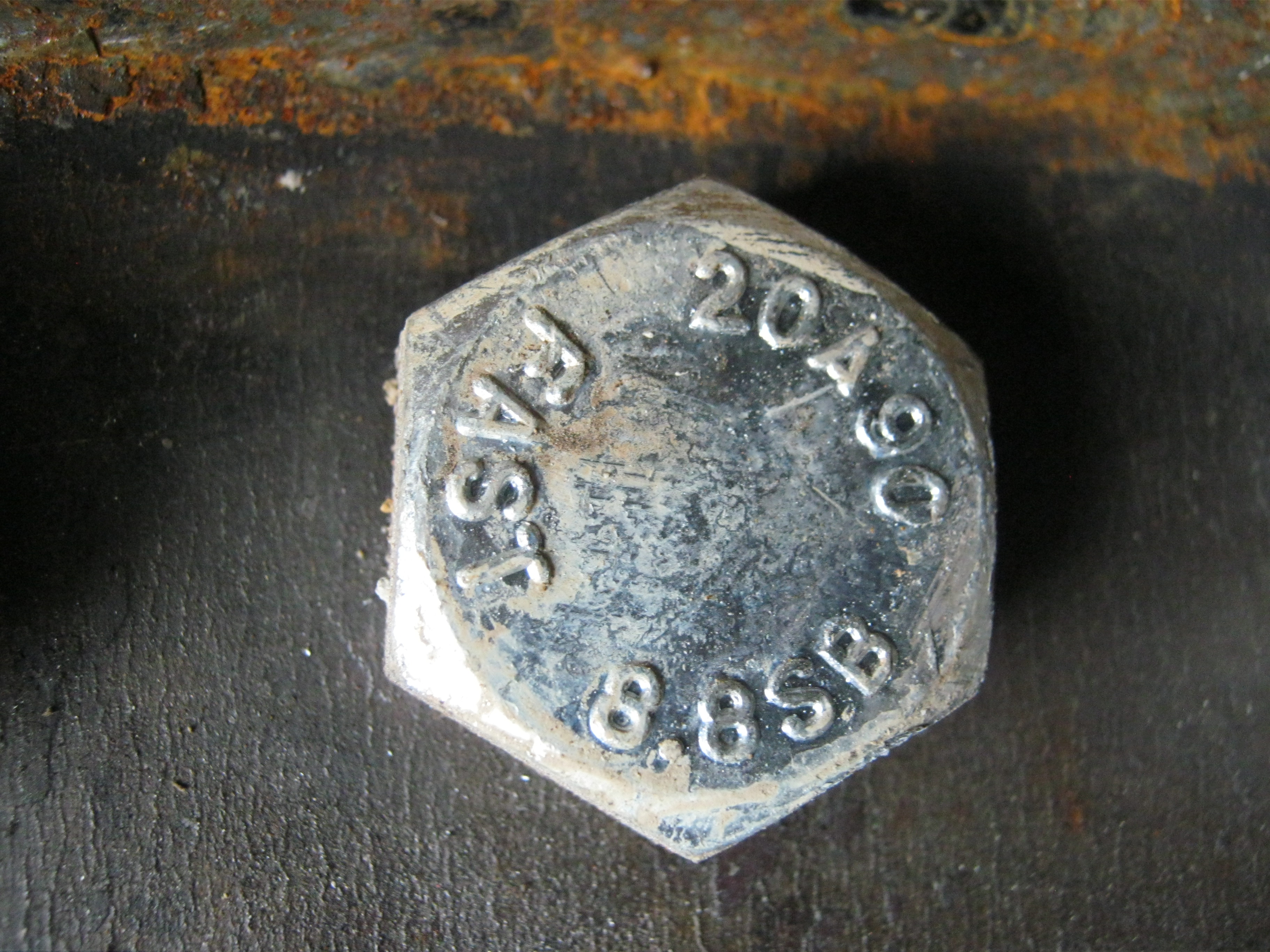
The bolts in question
So what is there to learn? All sub-contractors need to sign off their work (DAM were responsible for the bolts and they had no sign off directly to Mace); Sub-contractors need close supervision (no surprise there); Hit bolts with a hammer to get an idea of how tight they are; And finally understand what checking procedure has been used prior to you checking something.
Have I missed anything???
The key question I haven’t answered to myself is whether we (Mace) should have done a random check of bolt tightness? You chould say yes, but then we’d have a lot of other bolts to check too. I guess it’s all about the risk associated with that particular bolted connection!!!
