Bridge Traffic Barrier Upgrade
I have been working on a design for the replacement of the existing traffic barrier to one that complies with current standards. The bridge in question is a rail overbridge in the heart of Sydney, it is approximately 100 years old and of ‘jack arch’ contrsuction. Jack arch bridges are somewhat more prevalent in the UK rather than Australia and the tendency here is to Heritage List a structure of that age in an attempt to broaden or find some cultural significance. Fortunately the bridge itself is not Heritage Listed but some of the surrounding rail buildings are which may impact the design aesthetic of the upgrade. A Statement of Heritage Impact (SoHI) has been commissioned which will form part of the Review of Environmental Factors (REF) which at present is unlikely to cause any major dramas due to a previous upgrade in 1994 which replaced parts of the brick barrier/parapet wall to a metal railing. So in effect the current heritage aesthetic is not really in keeping of early 20th century and a full replacement is more likely to improve uniformity.
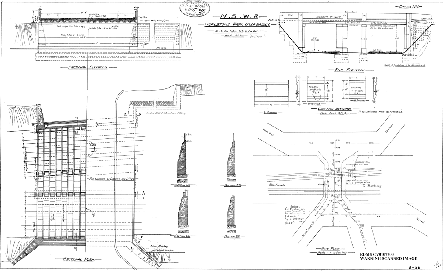
At present I have designed an L shaped pre-cast section to be retrofitted on top of the current I beam-jack arch arrangement but due to the close proximity of a gas main I am unable to get the base to span across two of the steel sections and current arrangements have the pre casts ection chemically anchored into either the existing fill or more likely new concrete fill which means the jack arch will have to be removed. This is a design I inherited from the concept design stage and I have taken it forward and designed the concrete section to current traffic impact loads which conform to a ‘regular’ level of performance (250kN horizontal load acting across 1.1m at a height of 1.1m above the deck surface). I have built up a model within Microstran of the deck to see how the forces are transmitted through the various members and right at teh start it seemed obvious that the torsional capcity of the outside RSJ would govern. This is because there is very little lateral restaint. I modelled the deck using RSJ’s and plate girder longitudinally as per the originally drawings and then inserted masonry blocks between the girders to simulate the brick/concrete infill of the arches. There are steel tie rods between most of the girders but for the sake of conservatism I assumed there contribution to be negligible. There is some guidance in the HA’s DMRB, BA 16/97 and BD 61/10 which if you take the conservative approach as we don’t know what the fill between the arches is made up of requires the bridge to be analysed non-compositely. I thought I would try to ascertain the torsional capacity of the outside girder and found out that it is more complicated than I or anyone else in the office cares to pursue. Ultimately an I section will be affected by pure torsion (think G’s and J’s from phase 1) but warping torsion will govern. It seems design codes around the world tend to either ignore it or advise you to change your design so that torsion is insignificant and nothing to worry about.
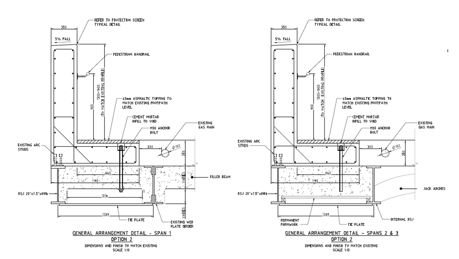
I think the design needs to enable the precast section to span over at least the inside two girders so that shear studs on the top flanges can enable the end section to act compositely and engage more of the deck due to the impact load. This will also mean that we will not have to remove any of the jack arches which will mean we won’t need any temporary works underneath the bridge to protect the tracks and ultimately mean less construction time and distruption due to weekend possessions because we could do all the work from the top. Alternatively I think some for of tie plates will need to be welded onto the bottom flanges to provide the required resistance which means further work to be carrier out from underneath. Providing this additional room for a wider pre cast section to span will result in haing to relocate a number of services (at least the water and gas mains and probably fibre optics to within conduits placed within the precast sections. I think this would still be an easier, safer and quicker way to carry out the works ratehr tahn being afraid to go near the gas main and designing around it which seems to have been the method previously employed.
Someone happened to drive past the site the other week and noticed that all the services within the walkways had been marked out. This would be useful information and I would have had to have employed someone to do this very shortly but it has taken me two days so far without success to try and track down who initiated it so I could get the survey data. The council as well as the asset owner no nothing about it, I have concluded there must a rogue contractor out there armed with a GPR unit locating services around Sydney at will for free!

Jon
Many thanks for this – very interesting with practical issues
Regards
Just to get warping sorted….when you twist a section( that’s not a closed section) parts of the cross section extend differentially longitudinally…. that’s what warping is….if this differential longitudinal strain is constrained the (would be) strain becomes an equivalent stress ( just as if you’d restained a piece of metal and heated it up) As usual the implied compressive stresses are not your fried because they might imply a shear towards a failure state but ( usually for plated section) the direct stresses may cause a plate buckle
Well that’s that covered then. In this case the warping strain is (sort of) restrained by the adjacent deck so does not accumulate to a restrained end …so my collies and not wobbling…furthermore if, in option 2, you form what is effectively a closed section ( from the adjacent longitudinal beams) and then apply the implied torsion….AND don’t go out of your way to restrain the ends at the abutments….all should be sweetness and light